Application of optical single-sideband laser in Raman atom interferometry
Lingxiao Zhu,1 Yu-Hung Lien,1,* Andrew Hinton,1,2 Alexander Niggebaum,1 Clemens Rammeloo,1 Kai Bongs,1 and Michael Holynski1,3
1School of Physics and Astronomy, University of Birmingham, Edgbaston, Birmingham B15 2TT, UK
2Quantum Metrology Laboratory, RIKEN, Wako, Saitama 351-0198, Japan
3m.holynski@bham.ac.uk
*y.lien@bham.ac.uk
Abstract
A frequency doubled I/Q modulator based optical single-sideband (OSSB) laser system is demonstrated for atomic physics research, specifically for atom interferometry where the presence of additional sidebands causes parasitic transitions. The performance of the OSSB technique and the spectrum after second harmonic generation are measured and analyzed. The additional sidebands are removed with better than 20 dB suppression, and the influence of parasitic transitions upon stimulated Raman transitions at varying spatial positions is shown to be removed beneath experimental noise. This technique will facilitate the development of compact atom interferometry based sensors with improved accuracy and reduced complexity.
OCIS codes: (020.1335) Atom optics; (020.1670) Coherent optical effects; (120.5060) Phase modulation.
References and links
- [1] M. Kasevich and S. Chu, “Atomic interferometry using stimulated Raman transitions,” Phys. Rev. Lett. 67, 181 (1991).
- [2] C. Freier, M. Hauth, V. Schkolnik, B. Leykauf, M. Schilling, H. Wziontek, H.-G. Scherneck, J. Müller, and A. Peters, “Mobile quantum gravity sensor with unprecedented stability,” J. Phys.: Conf. Ser. 723, 012050 (2016).
- [3] F. Sorrentino, Y.-H. Lien, G. Rosi, L. Cacciapuoti, M. Prevedelli, and G. M. Tino, “Sensitive gravity-gradiometry with atom interferometry: progress towards an improved determination of the gravitational constant,” New J. Phys. 12, 095009 (2010).
- [4] T. L. Gustavson, A. Landragin, and M. A. Kasevich, “Rotation sensing with a dual atom-interferometer sagnac gyroscope,” Class. Quantum Grav. 17, 2385 (2000).
- [5] B. Altschul, Q. G. Bailey, L. Blanchet, K. Bongs, P. Bouyer, L. Cacciapuoti, S. Capozziello, N. Gaaloul, D. Giulini, J. Hartwig, L. Iess, P. Jetzer, A. Landragin, E. Rasel, S. Reynaud, S. Schiller, C. Schubert, F. Sorrentino, U. Sterr, J. D. Tasson, G. M. Tino, P. Tuckey, and P. Wolf, “Quantum tests of the Einstein equivalence principle with the STE-QUEST space mission,” Adv. Space Res. 55, 501 – 524 (2015).
- [6] K. Bongs, M. Holynski, and Y. Singh, “ in the sky,” Nat. Phys. 11, 615–617 (2015).
- [7] A. Hinton, M. Perea-Ortiz, J. Winch, J. Briggs, S. Freer, D. Moustoukas, S. Powell-Gill, C. Squire, A. Lamb, C. Rammeloo, B. Stray, G. Voulazeris, L. Zhu, A. Kaushik, Y.-H. Lien, A. Niggebaum, A. Rodgers, A. Stabrawa, D. Boddice, S. R. Plant, G. W. Tuckwell, K. Bongs, N. Metje, and M. Holynski, “A portable magneto-optical trap with prospects for atom interferometry in civil engineering,” Phil. Trans. R. Soc. A 375, 20160238 (2017).
- [8] J. Le Gouët and J. Kim and C. Bourassin-Bouchet and M. Lours and A. Landragin and F. Pereira dos Santos, “Wide bandwidth phase-locked diode laser with an intra-cavity electro-optic modulator,” Opt. Commun. 282, 977 (2009).
- [9] P. Bouyer and T. L. Gustavson and K. G. Haritos and M. A. Kasevich, “Microwave signal generation with optical injection locking,” Opt. Lett. 21, 1502 (1996).
- [10] M. Kasevich and D. S. Weiss and E. Riis and K. Moler and S. Kasapi and S. Chu, “Atomic velocity selection using stimulated Raman transitions,” Phys. Rev. Lett. 66, 2297 (1991).
- [11] V. Ménoret and R. Geiger and G. Stern and N. Zahzam and B. Battelier and A. Bresson and A. Landragin and P. Bouyer, “Dual-wavelength laser source for onboard atom interferometry,” Opt. Lett. 36, 4128 (2011).
- [12] V. Schkolnik and O. Hellmig and A. Wenzlawski and J. Grosse and A. Kohfeldt and K. Döringshoff and A. Wicht and P. Windpassinger and K. Sengstock and C. Braxmaier and M. Krutzik and A. Peters, “A compact and robust diode laser system for atom interferometry on a sounding rocket,” Appl. Phys. B: Lasers Opt. 122, 217 (2016)
- [13] P. Cheinet and F. Pereira dos Santos and T. Petelski and J. Le Gouët and J. Kim and K. T. Therkildsen and A. Clairon and A. Landragin, “Compact laser system for atom interferometry,” Appl. Phys. B: Lasers Opt. 84, 643 (2006).
- [14] S. Merlet and L. Volodimer and M. Lours and F. Pereira dos Santos, “A simple laser system for atom interferometry,” Appl. Phys. B: Lasers Opt. 117, 749 (2014).
- [15] F. Theron, O. Carraz, G. Renon, N. Zahzam, Y. Bidel, M. Cadoret, and A. Bresson, “Narrow linewidth single laser source system for onboard atom interferometry,” Appl. Phys. B: Lasers Opt. 118, 1–5 (2015).
- [16] “Muquans Absolute Quantum Gravimeter,” https://www.muquans.com/index.php/products/aqg
- [17] O. Carraz and R. Charrière and M. Cadoret and N. Zahzam and Y. Bidel and A. Bresson, “Phase shift in an atom interferometer induced by the additional laser lines of a Raman laser generated by modulation,” Phys. Rev. A 86, 033605 (2012).
- [18] C. F. Buhrer and D. Baird and E. M. Conwell, “Optical frequency shifting by electro-optic effect,” Appl. Phys. Lett. 1, 46 (1962).
- [19] P. Page and H. Pursey, “Tunable single sideband electro-optic ring modulator,” Opto-electronics 2, 1 (1970).
- [20] M. Izutsu and S. Shikama and T. Sueta, “Integrated optical SSB modulator/frequency shifter,” IEEE J. Quantum Electron. 17, 2225 (1981).
- [21] B. J. Cusack and B. S. Sheard and D. A. Shaddock and M. B. Gray and P. K. Lam and S. E. Whitcomb, “Electro-optic modulator capable of generating simultaneous amplitude and phase modulations,” Appl. Opt. 43, 5079 (2004).
- [22] A. Hangauer and G. Spinner and M. Nikodem and G. Wysocki, “High frequency modulation capabilities and quasi single-sideband emission from a quantum cascade laser,” Opt. Express 22, 23439 (2014).
- [23] S. Shimotsu and S. Oikawa and T. Saitou and N. Mitsugi and K. Kubodera and T. Kawanishi and M. Izutsu, “Single side-band modulation performance of a integrated modulator consisting of four-phase modulator waveguides,” IEEE Photonics Technol. Lett. 13, 364 (2001).
- [24] J. L. Hall and M. Zhu and P. Buch, “Prospects for using laser-prepared atomic fountains for optical frequency standards applications,” J. Opt. Soc. Am. B 6, 2194 (1989).
- [25] P. D. Lett and W. D. Phillips and S. L. Rolston and C. E. Tanner and R. N. Watts and C. I. Westbrook, “Optical molasses,” J. Opt. Soc. Am. B 6, 2084 (1989).
- [26] A. Peters, K. Y. Chung, and S. Chu, “High-precision gravity measurements using atom interferometry,” Metrologia 38, 25 (2001).
- [27] K. Takase, “Precision rotation rate measurements with a mobile atom interferometer,” Ph.D. thesis, University of Stanford (2008).
- [28] D. M. S. Johnson, J. M. Hogan, S.-W. Chiow, and M. A. Kasevich, “Broadband optical serrodyne frequency shifting,” Opt. Lett. 35, 745–747 (2010).
1 Introduction
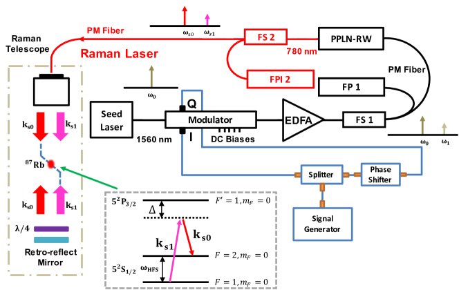
Raman atom interferometry (RAI), first demonstrated over 25 years ago [1], has enabled the creation of the most precise laboratory measurement devices for absolute gravity [2], gravity gradients [3] and rotation [4]. This makes atom interferometry a promising quantum technology for applications ranging from fundamental physics in space [5, 6] to practical concerns such as civil engineering [7]. These applications require the translation of laboratory systems into small, robust and low-power devices, which poses particular challenges for the light source. Raman atom interferometers as illustrated in Fig. 1 use a two-photon transition to couple two hyperfine levels of the atomic ground state. This allows manipulation of the atom to split, redirect and recombine its quantum mechanical wave function, encoding the gravitational phase shift between the two trajectories in the relative atomic populations of the two hyperfine levels. This demands two laser beams with a frequency difference matching the ground state hyperfine splitting, typically several GHz, and the relative optical phase coherence at the mrad level over several hundred ms.
Laboratory versions of the Raman atom interferometer light source have been implemented through optical phase locking [8], acousto-optic modulators (AOM) [9] and electro-optic modulators (EOM) [10]. Some state-of-the-art Raman laser systems have been developed for very stringent payload limitation and harsh environment [11, 12]. Recent quantum technology developments focus on robust telecoms technology with electro-optic modulation and frequency doubling [13, 14, 15, 16], which in principle allow the realisation of an entire atom interferometer from a single laser source. However, the EOM scheme usually produces a double sideband (DSB) spectrum which contains redundant sidebands. These redundant sidebands not only waste optical power but also introduce extra undesirable interactions which affect the system systematics and impair performance [17]. Here we demonstrate a laser system for RAI, which maintains the compactness and simplicity of EOM systems without the adverse effects of the redundant sidebands.
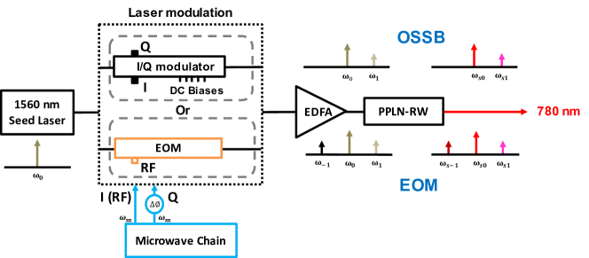
The system relies on I/Q modulator based optical single-sideband generation (OSSB) [18, 19, 20, 21, 22], with the novel feature of maintaining the single sideband modulation through an optical frequency doubling element. Our OSSB system is shown schematically in Fig. 1. The first stage comprises a 1560 nm fibre laser and an I/Q modulator for single sideband generation. The output is then converted into 780 nm by second harmonic generation (SHG) to resonate with the D2 line. The I/Q modulator allows implementing OSSB with a high degree of versatility allowing the optimization of undesired sideband suppression after the optical frequency doubler. The SHG unavoidably pairs up different spectral components in 1560 nm OSSB and converts them into 780 nm, which requires optimization in order to avoid suppressed sidebands in the fundamental band reemerging in the frequency doubled spectrum. We measure the spectra of our OSSB, including both fundamental and SHG. We finally implement the full-carrier optical single sideband scheme (FC-OSSB) as an interrogation laser for RAI. We demonstrate that the FC-OSSB Raman laser suppresses the influence of undesired sidebands, by measuring the spatial dependence of the Rabi frequency and interferometric phase shift and comparing this to that of an EOM modulation scheme. At the end, we include the theory for the I/Q modulator based OSSB, the SHG spectrum of OSSB, and relevant notations in the appendix.
2 Apparatus
Our Raman atom interferometer including an FC-OSSB based Raman laser is illustrated in Fig. 1. The Raman laser comprises a highly stable 1560 nm fibre laser (Rock™, NP Photonics), a fibre-coupled I/Q modulator (MXIQ-LN-40, iXBlue), an erbium-doped fibre amplifier (EDFA) (YEDFA-PM, Orion Laser), and a nonlinear wavelength conversion module (WH-0780-000-F-B-C, NTT Electronics). The I/Q modulator is essentially a dual parallel Mach-Zehnder modulator (MZM) [20, 23]. The in-phase and quadrature ports of the I/Q modulator are driven by the same RF signal except an RF phase shifter is installed on the quadrature port to generate the necessary phase shift. The optical phase shifters are separately controlled by separate precision voltage sources. The output of the fibre laser is modulated by the I/Q modulator to generate FC-OSSB, which is amplified by the EDFA to 1 W. The nonlinear wavelength conversion module based on a periodically poled lithium niobate ridge waveguide (PPLN-RW) is used to convert the FC-OSSB signal to 780 nm. The optical power of 780 nm light is approximately 440 mW. The spectra of both 1560 nm and 780 nm are simultaneously monitored by two Fabry-Pérot interferometers (FPI) (SA210-12B, SA200-5B, Thorlabs) with free spectral range (FSR) 10 GHz and 1.5 GHz respectively. The two major frequencies in the 780 nm FC-OSSB spectrum drive a two-photon Raman transition between the ground state hyperfine levels with a detuning which is illustrated in the inset of Fig. 1. As shown in next section, other sidebands are strongly suppressed compared with these two frequencies.
In the beginning of the experiment, atoms are loaded into a 3D magneto-optical trap and then launched into the interrogation region by the moving molasses technique [24, 25]. The Raman laser beam is directed into the interrogation region and retro-reflected by a mirror. The light field inside the interrogation region consists of two counter-propagating beams which contain two frequencies. In principle, there are four different combinations that can drive the two-photon Raman transition used in RAI. Nevertheless, only one pair, as illustrated in Fig. 1, is selected by Doppler selection and the polarization. When the atoms are in the interrogation region a Raman pulse sequence is applied to perform RAI. The phase shift of RAI is determined by measuring the population ratio of the ground state hyperfine levels. In the case of a local gravity acceleration , is given by:
| (1) |
where are the populations of the ground state hyperfine levels F = 1 and 2, the interferometric time is the interval between adjacent Raman pulses, is the chirp rate of for compensating the Doppler shift, and is the effective wave vector [1].
3 Results
3.1 Spectra of OSSB
The system was then used to demonstrate that FC-OSSB can be realized both before and after the SHG. According to Eq. (6) and (8), the OSSB spectrum at 780 nm is degraded due to the SHG. The sideband is not eliminated in 780 nm, and is generated by the sum frequency generation (SFG) between the sidebands and in 1560 nm. This is expressed as:
The sideband is proportional to the term:
As shown in Fig. 2, the amplitude of these unwanted sidebands depends on the setting of the modulator and the issue is further addressed in the appendix. To optimize the 780 nm FC-OSSB, We start from its counterpart at 1560 nm by adjusting and observing the suppression pattern of the different frequency components such as and . Further optimization is achieved by adjusting . Subsequently, the power and the spectrum of 780 nm OSSB are adjusted primarily through the modulation depth but also . Eventually the temperature of the wavelength conversion module is adjusted to shift the gain profile and finish the optimization.
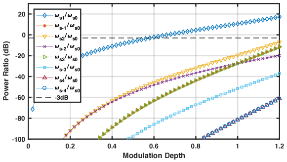
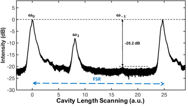
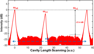
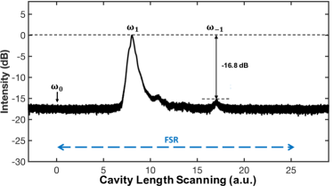
Figure 3(a) and 2(b) show the spectra of FC-OSSB in 1560 and 780 nm respectively. The FC-OSSB spectra shown are acquired with a power ratio , at -3 dB at 780 nm, as desired for compensating light shifts. The is not visible and the is approximately 21 dB below . Meanwhile, concerning the 1560 nm components, the is suppressed better than 20 dB compared with . In the measurement, the RF power applied to the I/Q ports of the modulator is 13 dBm which corresponds to based on the . According to the simulation in Fig. 2, the sideband to carrier ratio should be below -50 dB. The degeneration can be explained by the unbalanced RF power applied on the I and Q ports and the non-identical waveguides on the two arms of the modulator.
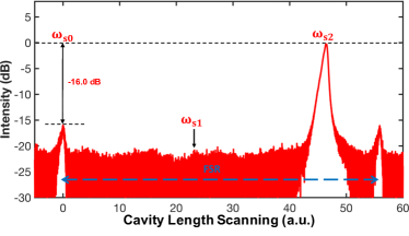
The I/Q modulator is also used to realize suppressed carrier OSSB (SC-OSSB). Figure 3(c) shows the spectrum of SC-OSSB in 1560 nm. The is suppressed to the noise level. Nevertheless the extinction ratio of is only better than -15 dB with respect to and the suppression of at 780 nm is considerably impaired. This is because the SFG occurs between and revives . The revival of the carrier at 780 nm is clearly seen in Fig. 3(d). The is only -16 dB compared with the frequency at . Meanwhile, the amplitude is beneath the noise level.
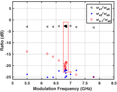
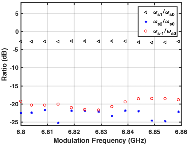
In many applications the modulation frequency needs to be tuned, for example, Doppler compensation during free fall in RAI. The tuning of may produce unwelcome side effects such as degradation of suppression and power ratio variation of . These would primarily be caused by the frequency dependent characteristics of the microwave electronics driving the I/Q modulator. The dependence of the FC-OSSB performance with was investigated, and the results for within 4–8 GHz are shown in Fig. 4(a). Figure 4(b) shows the enlarged region covering the experimental frequency chirping for Doppler shift compensation. During scanning, the OPR of is set to be -3 dB. The sideband can be suppressed below -20 dB between 5 GHz and 8 GHz while the suppression of the sideband starts to increase below 6.8 GHz. This is because the RF devices have a frequency-dependent phase shift, which degrades the OSSB. However, for the range between 6.8 GHz and 6.86 GHz where the atom interferometer operates, the sideband is suppressed below -18 dB.
3.2 Interferometry fringe
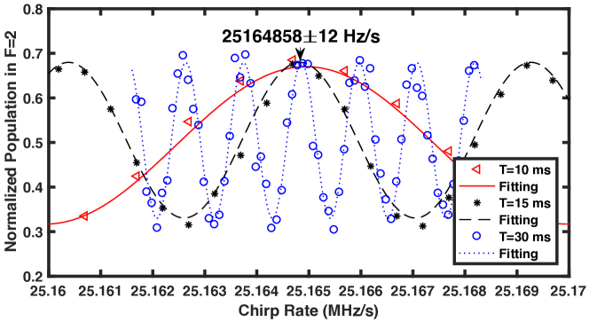
The FC-OSSB laser system was then used to perform a gravity measurement in a Mach-Zehnder atom interferometer, which combines three velocity sensitive Raman pulses [26]. In order to compensate the Doppler shift between the counter-propagating beams, induced by atoms in free fall, is swept at a chirp rate . From Eq. (1), at a specific chirp rate, the phase shift induced by the gravitational acceleration is canceled and there exists a stationary phase point independent of interferometric time . The value of is therefore derived from the frequency chirp rate and is given by . Figure 5 shows fringes with equal to 10 ms, 15 ms and 30 ms respectively. A central fringe is addressed where the interferometer phase is canceled for a Doppler compensation. The local gravity is determined as is obtained.
3.3 Spatial interference elimination
As demonstrated above, the Raman laser based on OSSB allows the suppression of the unwanted sidebands. Consequently, the interference caused by these unwanted laser lines can be eliminated. To verify this conclusion, the OSSB system is compared to an EOM scheme when applied in atom interferometry. The Raman laser setup is shown in Fig. 6, with only the modulator changing between comparisons.
3.3.1 Spatially dependent Raman transition
In EOM modulation, there are multiple pairs of frequencies that can drive resonant two-photon Raman transitions. The effective Rabi frequency contains a spatial dependence with a periodicity of , where is the wavelength of the RF signal applied on the EOM. This causes the transition condition to be modified for Raman transitions performed along the interferometry region. The effect is greater when the detuning is larger as the relative contribution from the unwanted frequency pairs increases [27].
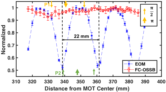
Raman pulses were applied at different positions along the longitudinal direction in the interferometry region. The pulse duration is set at 50 , which corresponds to the pulse duration at the start point. The RF frequency applied to the EOM and I/Q modulator is equal to the separation between the ground state hyperfine levels F = 1 and F = 2 (). Figure 7 shows the spatial dependence of the Raman transition. The wavelength of oscillations is measured to be 22 mm which matches with the half wavelength of the RF signal. The amplitude of the Raman transition was reduced a factor of two at the valley compared with the crest. The same measurement was repeated in the FC-OSSB scheme, showing that the spatial dependence is removed to below the experimental noise level. The fluctuation of the Raman transition is less than 10%, which is induced by other perturbation, and shows no oscillatory spatial structure. Although the interference effect in EOM scheme can be reduced with small detuning (), this increases contributions from spontaneous emission which can lead to loss the fringe contrast in atom interferometry experiments.
3.3.2 Phase shift and contrast
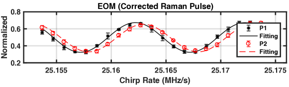
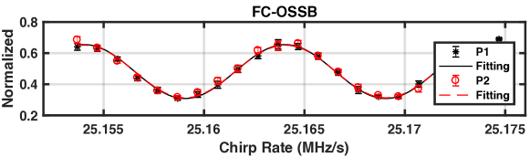
The unwanted sidebands in the EOM scheme can also induce a position dependent phase shift in atom interferometry [17]. To evaluate the performance of the OSSB system, both schemes were used to operate a Mach-Zehnder atom interferometer at two different sets of positions, P1 and P2, which are labelled in Fig. 7. The time separation between pulses was set to 10 ms. The sideband power ratio is chosen to be 1/2 to cancel the first order AC Stark shift.
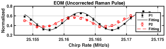
Figure 8 shows the atom interferometric fringes acquired by sweeping the chirp rate under different modulation configurations. In order to further investigate the effect arising from spatially varying Raman transition in EOM scheme, the measurements are performed under two different assumptions: (1) single global Rabi frequency; (2) spatially dependent Rabi frequency. In the first case, the Raman and pulse durations are set based on the Rabi frequency at the first position of P1. In the second case, all the pulse durations are set by the local Rabi frequency measurements. In the FC-OSSB scheme, the pulse durations are set by the Rabi frequency at the first position of P1. By fitting the data, the phase shifts and the contrasts for different conditions are extracted for comparison. The results are summarized in the table 1.
| Phase Shift (mrad) | Contrast | |||
|---|---|---|---|---|
| P1 | P2 | P1 | P2 | |
| EOM(U) | 1509 | 2077 | 22% | 12% |
| EOM(C) | 1759 | 1294 | 20% | 19% |
| OSSB | 597 | 596 | 21% | 20% |
With the EOM scheme, the fringes measured at P1 and P2 shift away from the fringes measured with the FC-OSSB scheme, regardless of whether the Raman pulses duration is corrected or not. Without correcting the Raman pulse duration in the EOM scheme, the phase measured at P1 and P2 has a relative phase difference 568 mrad. In addition, the contrast is reduced from 22% to 12%, nearly a factor of two decrease between P1 and P2. After correcting the Raman pulse duration, the fringe contrast at P2 can be recovered to 19% but there is still a spatially dependent phase difference at both P1 and P2. However, with the FC-OSSB scheme, the fringe at P2 is shifted by 1 mrad with a small contrast decrease around 1% compared with the one at P1. As proposed in the paper [17], the EOM scheme is still adoptable for atom interferometry application in high-precise gravity measurement by numerically calculate the phase shift induced by the unwanted laser lines in the EOM scheme, which demands the atom interferometer parameters are precisely estimated. However, the OSSB approach has been shown to effectively remove these concerns, and others, without adding additional complexity to the laser system.
4 Conclusion
The application of FC-OSSB in atomic physics, especially RAI, is demonstrated in this paper. The suppression of the spatially dependent Rabi frequency and the interferometric phase bias induced by undesired sidebands, which arise through existing single laser schemes, are shown to be suppressed to a level below the experimental noise of the atom interferometer. While enabling these improvements, the compact, robust and single laser nature of the EOM scheme is retained - allowing for the improvement of compact RAI based sensing. In addition, carrier suppression (SC-OSSB) to create an agile single frequency is also demonstrated, enabling future implementation as an efficient and broadband optical frequency shifter with the potential to significantly improve over techniques such as serrodyne modulation [28]. By aid of versatile microwave electronics, in principle, OSSB schemes can be combined to realize a broadly tunable single-laser light source for RAI.
Appendix: I/Q modulator based OSSB

Our I/Q modulator is based on a dual parallel Mach-Zehnder modulator (MZM) [20, 23]. The simplified structure is shown in Fig. 9. Sub-modulators, and , act as either single or double balance modulators controlled by the phase shifters . A third sub-modulator is essentially a combiner for with an extra phase shifter . Each arm of is simply a conventional phase modulator. Assuming the seed laser frequency and a modulation signal with modulation depth , the signals at locations (1)–(4) can be expressed by Bessel functions:
| (2) |
where denotes the th-order Bessel function and the coefficients , and are expressed as below:
| (3) | |||||
| (4) | |||||
| (5) |
The FC-OSSB can be achieved by setting :
| (6) |
We also can realize the suppressed-carrier optical single sideband (SC-OSSB) by setting to :
| (7) |
OSSB with second harmonic generation
The spectral coverage of OSSB can be further extended to where there are no convenient light sources or modulators available by nonlinear optical processes such as SHG. Unlike other nonlinear processes, the SHG of OSSB will unavoidably degrade the OSSB because of the self-mixing characteristics. The self-mixing process pairs the different frequency components of OSSB and creates undesired frequencies. For simplicity, we assume . In the case of FC-OSSB, the SHG signal can be expressed as:
| (8) |
where is the permittivity of vacuum and is the susceptibilities of the medium. The shorthand for the different frequency components is as:
and "s" is added to the subscript to refer the components after SHG:
Figure 2 shows the simulation of the optical power ratio (OPR) of the sidebands with respect to the carriers in 780 nm versus the modulation depth . Assuming , the power ratio of / is -3 dB while the other sidebands are suppressed better than -40 dB.
Similarly, the SHG of SC-OSSB can be expressed as:
| (9) |
It is independent of the modulation depth, meaning that we do not need to over-drive the modulator to achieve carrier suppression.
Funding
Engineering and Physical Sciences Research Council (EPSRC) (EP/M013294); Defence Science and Technology Laboratory (Dstl) (DSTLX-1000095040); Future and Emerging Technologies within the 7th Framework Programme for Research of the European Commission (FET) (FP7-ICT-601180)