All-optical photon transport switching in a passive-active optomechanical system
Abstract
We propose a feasible scheme to realize all-optical photon transport switching in a passive-active optomechanical system, consisting of one ordinary passive cavity, one active cavity and one common movable membrane oscillator of perfect reflection, driven by two strong control fields and two weak probe fields symmetrically. By means of the gain effect of the active cavity, many novel and valuable phenomena arise, such as frequency-independent perfect reflection (FIPR) first proposed in this paper, adjustable photon bidirectional transport, phase-dependent non-reciprocity and so on. The relevant parameters used for controlling the all-optical switching are precisely tunable by adjusting the strengths of control fields and the relative phase of probe fields. Furthermore, tunable fast and slow light can be realized in our system by accurately adjusting relevant parameters which is readily and feasible in experiments. These novel phenomena originate from the effective optomechanical coupling and the gain effect provide a promising platform for photonic devices, quantum network node fabrication and quantum information process (QIP).
pacs:
42.50.Wk, 42.65.Dr, 42.65.Sf, 42.82.EtI Introduction
Optomechanical systems attracted intense interest and numerous investigations in the past few decades due to the superiority that plenty of quantum phenomena can be exhibited in such macroscopic devices, which provides a promising platform to explore quantum science and the correlation between classical and quantum issues optooverview ; quantumopto . As a interdiscipline of microphysics and quantum optics, which primarily studying the interactions between the electromagnetic fields and mechanical systems, it has developed rapidly that series of advances born in recent years, e.g., optomechanically induced transparency (OMIT) OMITscience ; OMITnature ; OMITpra2013 ; doubleOMIT2014 , multiple quantum entanglement YDWangprl2013 ; tripartite2017 , signal absorption and amplification ab-am1 ; ab-am2 ; ab-am3 ; ab-am4 , photon blocked pblocked1 ; pblocked2 ; pblocked3 , optomechanically induced non-reciprocity reci1 ; reci2 ; reci3 and so on, which laying a solid foundation for controllable photon transport and quantum information process via macroscopical optomechanical devices.
Recently, quite a lot of creative and satisfactory phenomena arise in the systems containing active (gain) subparts, especially in so-called parity-time ()-symmetric systems, exhibiting extraordinary advantages compared with those in conventional passive-passive systems beamPT ; extend1 ; extend2 ; extend3 . The successful realization of symmetry in optical systems, including optomechanical systems, leads to so many novel breakthroughs recently, e.g., mechanical symmetry ptoslwl ; ptosxxw , -symmetry-breaking induced ultralow threshold chaos ptchaos , photon laser ptplaserjh ; ptlaserhb , optomechanically induced transparency (OMIT) ptOMITlwl ; ptOMITjh and enhanced photon blocked effect ptpblocked . In a recent study lylpra2017 , Liu et.al. proposed a single-cavity optomechanical system with an active mechanical resonator, by modifying the gain and loss of the mechanical resonator, a tunable optical signal amplification and absorption, untraslow light with a more robust group delay can be realized. In view of all above, it seems that a passive-active system can induce more beneficial properties compared with conventional passive-passive systems in some respects.
In this paper, we study a three-mode passive-active optomechanical system includes two indirectly coupled cavities and a common membrane oscillator which couples to the two cavity modes via optomechanical coupling due to radiation pressure. Our passive-active system exhibits a controllable photon transport by adjusting the strengths of control fields, relative phase of probe fields and the gain of the active cavity where all the relevant parameters are readily and precisely changed in experiments. It is worth pointing out that the frequency-independent perfect reflection (FIPR), which arises in the gain-loss-balanced case, is very different from the phenomena in passive-passive systems such as coherent perfect absorption (CPA), coherent perfect transmission (CPT) and so on which arise only in specific parameter regions and especially rely on the frequency of probe field Huang ; XBYan , is independent of all other parameters once the specific condition is met. Moreover, one can further realize tunable fast and slow light in each case discussed in this paper, which is effortless and feasible in experiments.
II Model and Methods
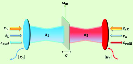
We consider a three-mode optomechanical system composed of a movable membrane oscillator located around the middle position between two fixed mirrors with finite equal transmission. As shown in Fig. 1, the movable membrane oscillator is perfectly reflected so that the system can be regarded in the form of two Fabry-Pérot cavities with one common mechanical resonator. The two cavity modes couple to the mechanical mode rather than couple to each other directly. Note here, the left cavity is passive while the right one is active by adding an optical gain medium or an additional external pumping field ptlaserhb ; ptchaos ; Schonleber2016NJP . We describe the left (right) cavity mode by photon annihilation and creation operators and ( and ) with identical eigenfrequency . And the mechanical mode can be described by phonon annihilation (creation) operator with eigenfrequency . The boson operators mentioned above satisfy the commutation relation ( and ). Two control and two probe fields are applied to drive the cavity modes on the left and right fixed mirrors symmetrically, with the amplitude () for the left (right) control field and () for the left (right) probe field, where is the decay rate of the left passive cavity (right active cavity). In addition, we have assumed identical eigenfrequency for the two control (probe) fields. Then the total Hamiltonian of the system after a frame rotation with respect to the control field frequency can be written as
| (1) | |||||
where has been set here for convenience. We introduce the detuning between cavity modes and control fields, the detuning between probe fields and control fields, the relative phase between the two probe fields. is the optomechanical coupling constant due to the radiation pressure where and are the effective mass of the mechanical resonator and the free length of the cavities, respectively.
Using the above Hamiltonian, considering relevant dissipation and quantum (thermal) noise, we can further obtain the following Heisenberg-Langevin equations Enhancing ; GenesMari ; XBYan
| (2) | |||||
where is the damping rate of the mechanical resonator which determines the mechanical quality factor . Moreover, is the zero-mean-value thermal noise operator of the mechanical resonator and is the zero-mean-value quantum noise operator of the left (right) cavity. Setting all the time derivatives in Eq. (2) to be zero, the steady-state values of the system variables can be obtained by neglecting the zero-mean-value noises and the weak probe fields
| (3) | |||||
where Re are the effective detunings between cavity modes and control fields due to the feedback of the motion of the mechanical resonator. Note a relatively weak optomechanical coupling and identical photon number in two cavities jointly lead to a negligible term Re compared with XBYan ; ptoslwl .
To solve Eq. (2), we can safely express relevant operators as sums of the steady-state mean values and the small quantum fluctuation terms, i.e., with . In this way, a set of linearized quantum Langevin equations can be obtained by neglecting all the nonlinear high-order terms of fluctuation operators and the zero-mean-value quantum noise operators after a rotating wave approximation
| (4) |
where is the detuning between the probe fields and the cavity modes. In addition, here we have moved Eq. (4) into an interaction picture by introducing the transformation
| (5) |
Moreover, we assume that the three-mode system is driven by two control fields at red-detuned sideband () and our system is studied in the resolved sideband regime (), the common mechanical resonator possesses a high quality factor and the eigenfrequency is assumed to be much larger than and to ensure the validity of the rotating wave approximation we have performed above XBYan .
According to Eq. (4), the time-dependent oscillating terms can be removed out if the solutions are assumed to be form: where . Note here, the component possesses the same Stokes frequency as the probe fields and and the component possesses the anti-Stokes frequency via a nonlinear four wave mixing process. Then it is easy to obtain such following results after effortless calculations
| (6) |
where and . We introduce the effective optomechanical coupling rate and the photon number ratio of two cavities. Without loss of generality we set and real in derivative process of Eq. (6).
According to the input-output field theory walls ; scully , we can straightforward derive the expression of both the left and right output fields and
| (7) |
the time-dependent oscillating terms can also be removed out similar to Eq. (6) if the solutions here have the same form and . Note again, the output components and possess the same frequency as the probe fields, the output components and possess the frequency but not of our interest in this paper. Then according to Eq. (6) and Eq. (7), we have
| (8) |
We introduce the transmission rate () and the reflection rate () for the left (right) cavity, respectively, which are used for gauging the intensities of the output fields from both cavities. Then we introduce arg (arg) and arg (arg) the phase of the reflection (transmission) field of the left and right cavity, respectively, which are functions of . In optomechanics, the group delay can be determined by the slope of the output field phase with respect to the probe frequency, i.e., ()GKH ; lylpra2017 . Note a positive corresponding to a slow light phenomenon while a negative corresponding to a fast light phenomenon on the contrary. One can see the larger the slope, the larger the group delay, thereby the slower the light.
III Results and Discussion
Now we will study numerically how the gain effect of the active cavity impacts the photon transport of such an optomechanical system by setting a negative value. To start with, we should consider the assumption we mentioned above that is reasonable in our system. According to Eq. (3), the photon number ratio can be indicated as when is satisfied. Thus we can guarantee the equal photon number in the two cavities by adjusting or (and) even if , and in turn, this further ensures the validity of Re in the preceding part of the text. In this section, we find several novel and fascinating phenomena arise in different parameter regimes which are accessible experimentally, such as (i) G-dependent photon bidirectional transport; (ii) frequency-independent perfect reflection (FIPR); (iii) phase-dependent non-reciprocity and (iv) fast and slow light.
III.1 Photon bidirectional modulator
According to Eq. (6) and Eq. (8), if no probe field is applied to the right active cavity () and the relevant parameters of our system simultaneously satisfy , the reflection and transmission rate of the left incident probe field can be written as
| (9) |
we have and when the left probe field is resonant with the cavity exactly (). So one can easily find that the transmission rate is proportional to the effective optomechanical coupling rate monotonously while the reflection rate experiences a transition from reduction to growth versus a increasing . The numerator of shows that the reflection field vanishes at and enters the amplification region at the critical point . Note, by increasing from to the reflection rate decreases from to while the transmission rate increases from to . Thus a photon bidirectional modulator can be realized which enables to continuously adjust the intensity ratio between the reflection and transmission field, means one can control the direction of the output field and the intensity of each direction component.
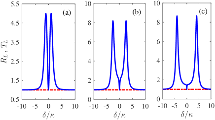
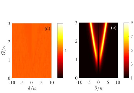
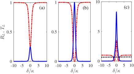
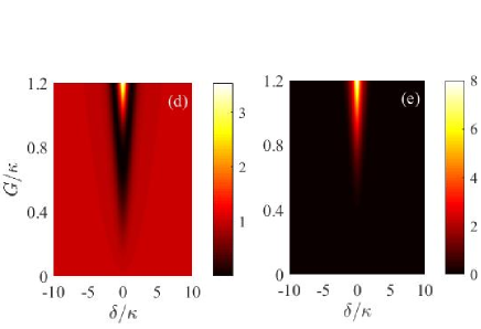
Fig. 2 shows the numerical results of the photon transmission in this case. According to Fig. 2 (a), (b) and (c), one can observe that just as we predicted analytically, the transmission rate increases in direct proportion to with the resonance condition while the reflection rate experiences a transition. Physically, it is because the two cavities exchange energy with the common mechanical oscillator via radiation pressure rather than a direct coupling, there exits a competition between dissipation of the mechanical oscillator and the indirect compensation effect. A relatively weak effective optomechanical coupling rate cannot support a timely and effective compensation from the active cavity to the passive cavity, within this regime, a increasing energy exchange between the left cavity mode and the mechanical mode due to the increasing leads to a greater loss of the left passive cavity. However, a big enough amount to a fast and strong tunneling between the two cavity modes so that an effective compensation effect arises, the indirect tunneling between the two cavity modes becomes dominant effect, which leads to a enhanced left output field (reflection field). In addition, a coherent-perfect-transmission phenomenon proposed in Ref.XBYan can be observed in Fig. 2 (b) at and Fig. 2 (c) near , so besides adjusting , controllable photon transport can also be realized via adjusting the frequency of probe field. Moreover, both the reflection and transmission field enter the amplification region while is larger than the critical point as shown in panel (c). Three-dimensional diagrams in Fig. 2 (d) and (e) exhibit the results in a more intuitive way, from which one can clear that how to adjust the photon transport by changing the strengths of control fields (thereby ) and the frequency of probe field (thereby ). In view of this, a G-dependent photon bidirectional modulator, i.e., an all-optical photon transport switching, can be realized.
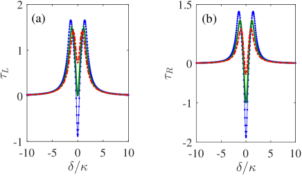
In this passive-active system, a tunable fast and slow light can also be realized at by adjusting the control fields. According to the analytical expression above, once the effective optomechanical coupling rate satisfies , the reflection rate will be in direct proportion to , so it’s significative to study the fast and slow light phenomenon of the reflection field in this region. In this case, we define the reflection group delay and the transmission group delay. In Fig. 3 (a), one can find a slow-to-fast light transition of the reflection field near the critical point . The group delay is inversely proportional to means a gradually faster reflected light, furthermore, decreases from positive to negative and the transition point is where as we predicted. The case in Fig. 3 (b) is slightly different, where the transmission group delay is always negative with , illustrating a algate fast light, decreases monotonously with a increasing at , so a gradually faster transmission light can also be achieved by increase the strengths of control fields and thereby the optomechanical coupling rate .
III.2 Frequency-independent perfect reflection
Generally, photon transport is sensitive to relevant parameters such as frequency of the probe field and the effective optomechanical coupling. Series of novel phenomena observed in various optomechanical systems, for instance, OMIT in -symmetric optomechanical systems ptOMITlwl ; ptOMITjh , coherent perfect absorption (CPA) in general optomechanical systems Huang ; XBYan , amplification of optical response in -symmetric-like optomechanical systems lylpra2017 and so on, arising only in the specific parameter regions. In this section, however, we will exhibit a parameter-independent novel photon phenomenon named frequency-independent perfect reflection (FIPR) by us.
We now consider the case that two probe fields with identical amplitudes () incident upon the left and right cavity respectively. Based on this, when conditions and are simultaneously satisfied. The transmission and reflection rate can be simplified as
| (10) |
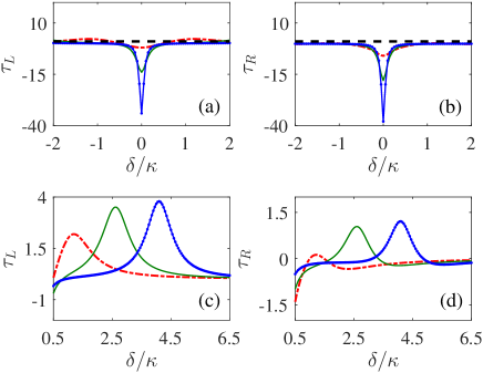
where we define the reflection rate and the transmission rate of the left incident probe field in this case. So it is clear that an invariable reflection rate is always tenable, as shown in Fig. 4, with no dissipation completely even if the loss rate of the cavity and mechanical oscillator is big enough, illustrating a perfect reflection in a fairly broad range of the probe frequency which has a promising prospect for photonic device fabrication. In addition, a remarkable amplification of the transmission field can be observed in Fig. 4. According to panels (a), (b) and (c), one can find that the degree of amplification is in direct proportion to and a controllable amplification can be realized. Panels (d) and (e) provide a more intuitive manifestation of our results, shows that the reflection field is also irrelevant to according with Eq. (10) and the amplified transmission field can be controlled by both the strengths of control fields and the frequencies of probe fields.
The case in Fig. 5 is much more different compared with that in Fig. 3. Here we define the reflection group delay and the transmission group delay of the left incident probe field. In panels (a) and (b), similar to Fig. 3, both and decrease with a increasing at , where , illustrating a tunable fast light with lossless reflection and transmission field can be realized in this system when the probe fields are resonant with cavity modes. Moreover, in panels (c) and (d), both the reflection and transmission group delay are in direct proportion to a increasing near the optimal value of where the transmission field has the maximal amplification effect according to Fig. 4 ( and corresponding to and , respectively). So we can realize a tunable slow light accompanied by a amplified transmission field and a lossless reflection field. In a word, by adjusting the strengths of control fields and the frequencies of probe fields, one can realize both fast and slow light for both the reflection and transmission fields.
Up to now in this section, we have chosen a fixed relative phase of the probe fields . Then we will show that except for adjusting and , is also an important control parameter for realizing a all-optical switching. If the condition is met, then we have
| (11) |
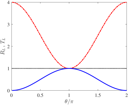
with resonant probe fields (). According to Eq. (11), when and when , as shown in Fig. 6. Moreover, both the reflection and transmission rate can be continuously adjusted via and the amplification effect of the transmission field relies on . Physically, it is because by adjusting the relative phase , the interference effect between the two probe fields can be changed, and this also impacts the compensation effect between the two cavity modes. In view of this, a phase-dependent all-optical switching can be realized by adjusting the relative phase of the probe fields and the strengths of the control fields.
IV Conclusions
In summary, we have studied theoretically how to control photon transport in a passive-active optomechanical system driven by two strong control fields and two weak probe fields. According to the main text, in virtue of the gain effect of the active cavity, series of novel and valuable phenomena arise, illustrating the realization of an all-optical photon transport switching. By adjusting the strengths of control fields, the frequencies of probe fields and the gain rate of the active cavity, we can realize: (i) a photon bidirectional modulator relying on the effective optomechanical coupling rate ; (ii) frequency-independent perfect reflection (FIPR) which subverts tradition so that the complete reflection in whole frequency region becomes possible. (iii) a phase-dependent photon switching by adjusting the relative phase of the probe fields. Furthermore, tunable fast and slow light can be realized in this passive-active optomechanical system by accurately adjusting the input fields and the gain rate of the active cavity in a experimentally reasonable region.
ACKNOWLEDGMENTS
Thanks Dr. Chu-Hui Fan for helpful discussions and Dr. Hong-Zhi Shen for constructive suggestions. Jin-Hui Wu is supported by National Natural Science Foundation of China under Grants No. 61378094, 11534002 and 11674049). Yi-Mou Liu is supported by National Natural Science Foundation of China under Grant No. 11704063. Lei Du and Yan Zhang acknowledge support from National Natural Science Foundation of China under Grant No. 11704064.
References
- (1) M. Aspelmeyer, T. J. Kippenberg, and F. Marquardt, Cavity optomechanics, Rev. Mod. Phys. 86, 1391 (2014).
- (2) W. P. Bowen and G. J. Milburn, Quantum Optomechanics (CRC Press, Boca Raton, 2016).
- (3) S. Weis, R. Rivière, S. Deléglise, E. Gavartin, O. Arcizet, A. Schliesser, and T. J. Kippenberg, Optomechanically Induced Transparency, Science 330, 1520(2010).
- (4) A. H. Safavi-Naeini, T. P. M. Alegre, J. Chan, M. Eichenfield, M. Winger, Q. Lin, J. T. Hill, D. E. Chang, and O. Painter, Electromagnetically induced transparency and slow light with optomechanics, Nature (London) 472, 69 (2011).
- (5) M. Karuza, C. Biancofiore, M. Bawaj, C. Molinelli, M. Galassi, R. Natali, P. Tombesi, G. Di Giuseppe, and D. Vitali, Optomechanically induced transparency in a membrane-in-the-middle setup at room temperature, Phys. Rev. A. 88, 013804 (2013).
- (6) P. C. Ma, J. Q. Zhang, Y. Xiao, M. Feng, and Z. M. Zhang, Tunable double optomechanically induced transparency in an optomechanical system, Phys. Rev. A 90, 043825 (2014).
- (7) Y.-D. Wang and A. A. Clerk, Reservoir-Engineered Entanglement in Optomechanical Systems, Phys. Rev. Lett. 110, 253601 (2013).
- (8) X. Yang, Y. Ling, X. Shao, and M. Xiao, Generation of robust tripartite entanglement with a single-cavity optomechanical system, Phys. Rev. A 95, 052303 (2017).
- (9) F. Massel, S. U. Cho, J. M. Pirkkalainen, T. T. Heikkilä, and M. A. Sillanpää, Multimode circuit optomechanics near the quantum limit, Nat. Commun. 3, 987 (2012).
- (10) X. Zhou, F. Hocke, A. Schliesser, A. Marx, H. Huebl, R. Gross, and T. J. Kippenberg, Control of microwave signals using circuit nano-electromechanics, Nat. Phys. 9, 179 (2013).
- (11) F. Massel, T. T. Heikkilä, J. M. Pirkkalainen, S. U. Cho, H. Saloniemi, P. J. Hakonen, and M. A. Sillanpää, Microwave amplification with nanomechanical resonators, Nature (London) 480, 351 (2011).
- (12) F. Monifi, J. Zhang, S. K. Özdemir, B. Peng, Y. X. Liu, F. Bo, F. Nori, and L. Yang, Optomechanically induced stochastic resonance and chaos transfer between optical fields, Nat. Photonics. 10, 399 (2016).
- (13) K. M. Gheri, W. Alge, and P. Grangier, Quantum analysis of the photonic blockade mechanism, Phys. Rev. A 60, R2673 (1999).
- (14) A. Majumdar and D. Gerace, Single-photon blockade in doubly resonant nanocavities with second-order nonlinearity, Phys. Rev. B 87, 235319 (2013).
- (15) Y. H. Zhou, H. Z. Shen, and X. X. Yi, Unconventional photon blockade with second-order nonlinearity, Phys. Rev. A 92, 023838 (2015).
- (16) X.-W. Xu and Y. Li, Optical nonreciprocity and optomechanical circulator in three-mode optomechanical systems, Phys. Rev. A 91, 053854 (2015).
- (17) X.-W. Xu, Y. Li, A.-X. Chen, and Y.-X. Liu, Nonreciprocal conversion between microwave and optical photons in electro-optomechanical systems, Phys. Rev. A 93, 023827 (2016).
- (18) Y. Li, Y. Y. Huang, X. Z. Zhang, and L. Tian, Optical directional amplification in a three-mode optomechanical system, Opt. Express 25, 018907 (2017).
- (19) K. G. Makris, R. El-Ganainy, and D. N. Christodoulides, Beam Dynamics in Symmetric Optical Lattices, Phys. Rev. Lett. 100, 103904 (2008).
- (20) K. G. Makris, R. El-Ganainy, D. N. Christodoulides, and Z. H. Musslimani, Beam Dynamics in Symmetric Optical Lattices, Phys. Rev. Lett. 100, 103904 (2008).
- (21) S. Klaiman, U. G nther, and N. Moiseyev, Visualization of Branch Points in -Symmetric Waveguides, Phys. Rev. Lett. 101, 080402 (2008).
- (22) A. Guo, G. J. Salamo, D. Duchesne, R. Morandotti, M. Volatier-Ravat, V. Aimez, G. A. Siviloglou, and D. N. Christodoulides, Observation of -Symmetry Breaking in Complex Optical Potentials, Phys. Rev. Lett. 103, 093902 (2009).
- (23) W. Li, C. Li, and H. Song, Theoretical realization and application of parity-time-symmetric oscillators in a quantum regime, Phys. Rev. A 95, 023827 (2017).
- (24) X.-W. Xu, Y.-X. Liu, C.-P. Sun, and Y. Li, Mechanical PT symmetry in coupled optomechanical systems, Phys. Rev. A 92, 013852 (2015).
- (25) X.-Y. Lü, H. Jing, J.-Y. Ma, and Y. Wu, -Symmetry-Breaking Chaos in Optomechanics, Phys. Rev. Lett. 114, 253601 (2015).
- (26) H. Jing, S. K. Özdemir, X.-Y. Lü, J. Zhang, L. Yang, and F. Nori, -Symmetric Phonon Laser, Phys. Rev. Lett. 113, 053604 (2014).
- (27) B. He, L. Yang, and M. Xiao, Dynamical phonon laser in coupled active-passive microresonators, Phys. Rev. A 94, 031802(R) (2016).
- (28) W. Li, Y. Jiang, C. Li, and H. Song, Parity-time-symmetry enhanced optomechanically-induced-transparency, Sci. Rep. 6, 31095 (2016).
- (29) H. Jing, Ş. K. Özdemir, Z. Geng, J. Zhang, X.-Y. L , B. Peng, L. Yang, and F. Nori, Optomechanically-induced transparency in parity-time-symmetric microresonators, Sci. Rep. 5, 9663 (2015).
- (30) J. Li, R. Yu, and Y. Wu, Proposal for enhanced photon blockade in parity-time-symmetric coupled microcavities, Phys. Rev. A 92, 053837 (2015).
- (31) Y.-L. Liu, R. Wu, J. Zhang, S. K. Özdemir, L. Yang, F. Nori, and Y.-X. Liu, Controllable optical response by modifying the gain and loss of a mechanical resonator and cavity mode in an optomechanical system, Phys. Rev. A 95, 013843 (2017).
- (32) X.-B. Yan, C.-L. Cui, K.-H. Gu, X.-D. Tian, C.-B. Fu, and J.-H. Wu, Coherent perfect absorption, transmission, and synthesis in a double-cavity optomechanical system, Opt. Express 22, 4886-4895 (2014).
- (33) G. S. Agarwal and S. Huang, Nanomechanical inverse electromagnetically induced transparency and confinement of light in normal modes, New J. Phys. 16, 033023 (2014).
- (34) D. W. Schönleber, A. Eisfeld, and R. El-Ganainy, Optomechanical interactions in non-Hermitian photonic molecules, New J. Phys. 18, 045014 (2016).
- (35) A. Farace and V. Giovannetti, Enhancing quantum effects via periodic modulations in optomechanical systems, Phys. Rev. A 86, 013820 (2012).
- (36) C. Genes, A. Mari, D. Vitalii, and S. Tombesi, Quantum Effects in Optomechanical Systems, Adv. At. Mol. Opt. Phys. 57, 33 (2009).
- (37) D. F. Walls and G. J. Milburn, Quantum Optics (Springer-Verlag, Berlin, 1994).
- (38) M. O. Scully and M. S. Zubairy, Quantum Optics (Cambridge, New York, 1997).
- (39) K.-H. Gu, X.-B. Yan, Y. Zhang , C.-B. Fu , Y.-M. Liu , X. Wang, and J.-H. Wu, Tunable slow and fast light in an atom-assisted optomechanical system, Opt. Commun. 338, 569 (2015).