Coherently Enhanced Wireless Power Transfer
Abstract
Extraction of electromagnetic energy by an antenna from impinging external radiation is at the basis of wireless communications and power transfer (WPT). The maximum of transferred energy is ensured when the antenna is conjugately matched, i.e., when it is resonant and it has an equal coupling with free space and its load, which is not easily implemented in near-field WPT. Here, we introduce the concept of coherently enhanced wireless power transfer. We show that a principle similar to the one underlying the operation of coherent perfect absorbers can be employed to improve the overall performance of WPT and potentially achieve its dynamic control. The concept relies on coherent excitation of the waveguide connected to the antenna load with a backward propagating signal of specific amplitude and phase. This signal creates a suitable interference pattern at the load resulting in a modification of the local wave impedance, which in turn enables conjugate matching and a largely increased amount of energy extracted to the waveguide. We develop an illustrative theoretical model describing this concept, demonstrate it with full-wave numerical simulations for the canonical example of a dipole antenna, and verify it experimentally in both near-field and far-field regimes.
The antenna is a key element in wireless technology, including communications and power transfer C. A. Balanis (1997). The first antennas emerged at the time of the discovery of electromagnetic waves by H. Hertz in 1888 and, since then, this technology has been progressing continuously. A plethora of optimized antennas have been invented for radio, microwave, THz and optical frequencies, where they have become irreplaceable elements for quantum optics and interconnections on a chip Agio and Alú (2013); Novotny and Hecht (2012).
While wireless communications are well established, wireless power transfer (WPT), proposed in the beginning of 20th century by N. Tesla Brown (1984), has been experiencing a rebirth in recent years, caused by demonstrations that the WPT efficiency, i.e., the ratio of energy received by an antenna over the total amount of emitted energy, can be drastically enhanced in the so-called near-field WPT regime, when the power is transferred via resonant coupling Kurs et al. (2007). Transfer over a distance of 2 m with 45 efficiency in the kHz range via strongly coupled magnetic resonances between two metallic coils has been recently achieved Kurs et al. (2007), giving rise to research on ways of using this effect for several technologies, in which recharging batteries without cables and wires would be of great importance. Examples include electric vehicles, implanted medical devices Hoa et al. (2014), and consumer electronics Kim et al. (2013); Mei and Irazoqui (2014); Kim et al. (2012). Significant research efforts have been recently devoted in exploring ways to achieve high WPT efficiency Song et al. (2017), optimizing the resonators’ geometry Song et al. (2016), the surrounding materials Wang et al. (2011); Urzhumov and Smith (2011); Kim et al. (2013), and their relative arrangement Kurs et al. (2007). In addition, great progress has been recently made to ensure the overall robustness of near-field WPT systems as a function of variations in the environment and background, using active systems, nonlinearity and feedback Assawaworrarit et al. (2017); Ra’di et al. (2017). Since near-field WPT systems require that receiving and transmitting antennas are resonant and, thus, restrict their minimal sizes and relative distances, they are quite impractical for modern WPT systems, which mostly rely on far-field non-resonant WPT technology Song et al. (2017).
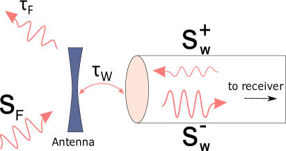
In this letter, we propose a conceptually different approach to realize robust WPT systems, relying on the local control of the wave impedance offered by interference phenomena. Recent research has shown that electromagnetic processes such as absorption and scattering may be effectively controlled via coherent spatial and temporal shaping of the incident electromagnetic field. For example, a coherent perfect absorber (CPA) is a linear electromagnetic system in which perfect absorption of radiation is achieved with two or more incident coherent waves, creating constructive interference inside an absorbing structure Chong et al. (2010, 2011); Zhang et al. (2012); Baranov et al. (2017). Similar principles also allow developing linear logic gates Fang et al. (2015) and pattern recognition setups Papaioannou et al. (2017), in which interference between two input waves is the enabling factor. In this Letter, we show that this approach can be employed to improve and control dynamically the matching of receiving antennas, and as a result enhance the overall performance of WPT systems and retune the system due to the changes in the channel link between transmitter and receiver. More specifically, we demonstrate that there is a possibility to improve the receiving efficiency of an antenna by coherent excitation of the outcoupling waveguide with a backward propagating signal of specific amplitude and phase, Fig. 1. This signal creates a specific interference pattern in the system that results in optimal wave impedance at the feed location, maximizing the energy transferred to the receiving antenna from free space. We develop an illustrative analytical model predicting this effect, demonstrate it in full-wave numerical simulations, and in a microwave experiment.
In order to demonstrate the effect of coherently enhanced power transfer, we develop a theoretical model on the basis of temporal coupled mode theory Haus (1984); Fan et al. (2003), which applies for both near-field and far-field WPT systems. The system of a waveguide-coupled antenna is schematically shown in Fig. 1. The antenna is excited by a field created by a transceiver, which can be either free-propagating or evanescent. The antenna couples to a waveguide with amplitude , which carries the out-coupled energy to the receiver. To model the structure, we will assume that the antenna has a single resonance at the operating frequency . The dynamics of the resonance mode amplitude can be described by the equation Haus (1984); Fan et al. (2003)
| (1) |
where is the mode damping time, is the coupling constants vector, and is the input amplitudes vector. The output amplitude vector , on the other hand, is related to the input vector and the resonance amplitude via
| (2) |
where is the direct scattering matrix, which reflects the direct pathway between input and output channels.
The two crucial parameters that determine the system response are and , being the antenna decay times into the waveguide mode and into radiation in free space, respectively. If the antenna does not exhibit large dissipative losses (which is a reasonable assumption in the microwave region), the total decay time is given by . The coupling constants are related to the corresponding decay times as and Fan et al. (2003). The direct scattering matrix, in turn, satisfies Fan et al. (2003).
Eqs. (1) and (2) establish the relation between the continuum of free-space modes and the discrete waveguide mode. The goal of efficient WPT is to enhance the amplitude of the back scattered waveguide mode, denoted by in Fig. 1. Therefore, for the sake of simplicity, we reduce the direct scattering matrix to a scalar , assuming that the coupling of the antenna with free-space modes leading to additional radiation losses is taken into account by . Such simplification does not undermine our model. Furthermore, for a microwave waveguide or coaxial cable it may be safely assumed that there is no direct scattering from the waveguide into free space (i.e., this interaction is mostly mediated by the antenna). Therefore, , and the resulting amplitude of the reflected mode that carries the transferred energy is given by
| (3) |
With this expression yields the reflection s-parameter () that can be easily measured experimentally or calculated numerically.
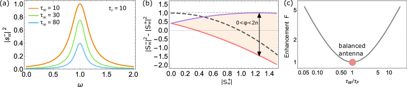
Without the back-propagating waveguide mode (), this expression results in a conventional Lorentzian spectrum for the transferred energy , reaching a maximum at the resonant frequency , see Fig. 2(a), where the calculations are presented for amplitude of the impinging free space mode . This maximum can be easily found from Eq. 3 and it is equal to . The optimal condition for coupling of the incident free space mode into the waveguide is known as the critical coupling, or conjugate matching condition C. A. Balanis (1997), and it is achieved when . This condition maximizes the amount of energy transmitted into the waveguide at resonance. While it is always possible to design the antenna so that the load resistance balances the radiation resistance to satisfy this condition, in practice as the environment, or generally the channel connecting transmitter and receiver, change, the load needs to be retuned to satisfy the conjugate matching condition. In the following, we show that it is possible to maximize transmission without affecting the coupling parameters, and retune the conjugate matching condition in real time by coherent illumination of the antenna from the loading port, similarly to the concept of coherent perfect absorption, when critical coupling for absorption in an unbalanced system is restored by an impinging coherent wave with proper phase and amplitude Chong et al. (2010); Baranov et al. (2017).
We now inspect how an auxiliary back-propagating wave impinging from the waveguide port at the load of the antenna can modify the input-output characteristic of the system. In Fig. 2(b) we show the energy balance in transferred energy, defined as the total received energy minus the energy spent in the auxiliary signal that is sent from the waveguide port to the load, as a function of the amplitude for different values of the relative phase . We chose the energy balance as a figure-of-merit since it allows to treat far-field and near-field WPT systems on an equal footing. A positive (negative) energy balance indicates that the antenna receives (radiates) more energy than radiates (receives). More importantly, if the energy balance exceeds the receiving energy for (no auxiliary signal), it signifies more favorable coherently assisted performance of the WPT system. For an antenna that is already conjugate matched (gray dashed line), as expected, the maximum power transfer arises when the auxiliary signal from the port is absent, since the signal would only detune the already optimal matching condition. This curve does not depend on the relative phase since the signal does not reflect back and, hence, does not alter the total receiving energy . However, for a mismatched antenna (shaded region in the plot, bounded between two colored lines) the input-output characteristic exhibits a peculiar behavior. The shaded region marks all achievable values of the energy balance for phase differences spanning the whole range between 0 and 2, indicating that for a suitable combination of phase and amplitude it is possible to achieve perfectly matched regime (the energy balance is positive and larger than in the case of no coherent excitation), even after subtracting the energy carried by the back-propagating signal. In particular, for a certain phase difference the amount of extracted power (purple curve) reaches the ideal value of a resonant critically coupled antenna. This coherent illumination restores the critical waveguide-antenna coupling, without having to retune the antenna load impedance. The specific value of optimal phase that ensures critical coupling depends on the direct scattering matrix ; if we allow direct pathways between the free space and the waveguide, or a reactive mismatch of the load, the phases of reflected and transmitted waves would be different and the optimal phase difference would change.
To better illustrate the capabilities of this approach, we show in Fig. 2(c) the enhancement factor defined as the ratio of maximum achievable transferred energy assisted by the auxiliary mode to the transferred energy without coherent illumination as a function of . It is seen that in the critically coupled case the enhancement factor equals 1, since the amount of transferred energy cannot be increased by coherent waveguide excitation. For mismatched antenna, on the other hand, the coherence-assisted enhancement factor increases with deviation of from 1, and therefore can have large values for strongly mismatched antennas. In the radio frequency range, mismatched and non-resonant antennas are common in the context of various wireless charging devices, in which the antenna, of cm scale length, is far off-resonant, since the radiation of the wireless transfer platform lying in the 100 kHz range Song et al. (2017). Our approach allows tuning the antenna to the optimal condition through wave interference. In addition, in many situations the matching condition can be easily detuned by changes in the background environment, for instance by neighboring parasitic reflections, or simply by a changing distance of the transmitter. Our approach offers a viable solution to real-time retuning of the antenna by sending a signal from the receiving port to modify the local wave impedance at the load.
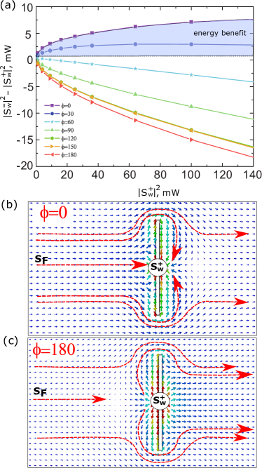
To verify the predictions of the analytical model, we carried out FDTD simulations of coherently enhanced WPT using the CST Microwace Studio. In our model, a coaxial cable was coupled to a non-resonant dipole antenna with 5 cm arm-length. Microwave radiation at 1.36 GHz (with a wavelength of 22 cm) from the open end of a rectangular waveguide separated by a distance of 40 cm from the antenna was used as the incident radiation (). A coherent auxiliary signal () was launched into the coaxial cable in order to enable the interference. The resulting dependence of the energy balance shown in Fig. 3(a) reproduces the theoretical predictions. We note that the relative phase denoted here as is calculated for the and taken at different points (at the dipole antenna center and at the rectangular waveguide end, respectively) and, hence, depends on their relative distance.
To provide more insight into the observed behavior, we present in Figs. 3(b,c) the Poynting vector distribution around the antenna considering the coherent excitation with relative phases of 0 deg [Fig. 3(b)] and 180 deg [Fig. 3(c)]. It is evident that, when the antenna is coherently excited by a wave of appropriate amplitude and phase, it enables largely enhanced antenna aperture that collects more energy into the coaxial cable from the propagating wave, Fig. 3(b). On the other hand, when the relative phase is not well chosen, the external wave () enables enhanced radiation of the dipole antenna into free space.
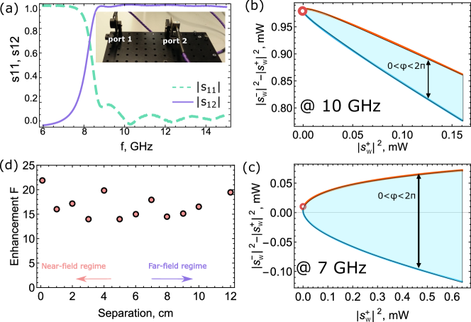
Finally, we perform a proof-of-principle experiment to demonstrate the feasibility of coherently enhanced WPT. For this purpose, we put together a microwave two-port system shown in the inset of Fig. 4(a). Each coaxial cable is connected to a vector network analyzer and terminated with a waveguide to coaxial adapter (WCA) that transforms electrical currents to propagating electromagnetic radiation. Fig. 4(a) presents the absolute values of measured and scattering parameters for arrangement of the system with the WCA faces next to each other. The WCAs have cutoff frequency around 8 GHz, which manifests itself in high reflection () at frequencies below 8 GHz. Thus, the WCA operates as a mismatched antenna for frequencies below 8 GHz and an almost matched antenna for frequencies above 8 GHz. The port 1 creates free space radiation sF, a part of which (s) then receives by port 2. The port 2 is excited by the auxiliary signal (s) of variable amplitude and phase.
The resulting -parameter spectra allow to observe coherently enhanced energy transfer. The dependence of the net extracted energy versus power of the additional excitation for the whole set of relative phases presented in Fig. 4(b) and (c) highlights the different behavior of the system in various spectral regions. At 10 GHz, where reflection by each WCA back to the coaxial cable is very low, excitation with the auxiliary signal barely improves the energy transfer, Fig. 4(b). At 7 GHz, however, the situation is strikingly different: high reflection by the WCA enables order of magnitude enhancement of the transferred power, Fig. 4(c). This enhancement becomes possible due to a small transmission from port 1 to port 2 even at 7 GHz, which can be increased by interference with the auxiliary signal.
To further inspect the opportunities offered by coherently enhanced energy transfer, we study the input-output behavior of our setup for different distances between the WCAs. Fig. 4(d) shows the enhancement factor versus the distance at the fixed frequency of 7 GHz (wavelength of 4.28 cm), where the WCAs operate as largely mismatched antennas. At each distance, the maximum of is achieved for a specific relative phase between the two signals, which is determined by complex values of -parameters for the given arrangement of the setup. An enhancement of the received energy around 20 can be achieved at this frequency for the whole range of distances (0–12 cm, which covers both near- and far-field regimes), highlighting the great versatility of the present approach for both near and far field WPT systems, and the possibility or realizing robust WPT independent of variations of the distance between transmitter and receiver.
We envision that in a practical WPT device, one may control in real time the amplitude and phase of the auxiliary signal to retune the antenna as a function of changes in the environment, temperature changes in the load, and distance of the transmitter. We propose the employment of an adaptive filter in the receiver circuit that monitors the transferred power and self-adjusts the amplitude and phase of the auxiliary signal such that it maximizes in real-time the transferred power.
In conclusion, we have shown that coherent signals sent from the receiving port of a WPT system can largely enhance and control the power transfer efficiency. This additional signal creates a tailored interference in the system, modifying the local wave impedance at the antenna load, thus enabling conjugate matching and critical coupling even if the antenna itself is largely mismatched, resulting in increased amount of energy extracted to the waveguide from free space. We have developed an illustrative analytical model predicting this effect and demonstrated it in numerical simulations and in a microwave experiment. Our approach of coherently enhanced WPT can be applied for the development of efficient wireless power transfer systems with robust operation in rapidly changing environments, as common in practical situations and setups.
The authors are grateful to Prof. Constantin Simovski and Prof. Sergei Tretyakov for their expert advice and helpful criticism during the elaboration of this work. This work was partially supported by the Air Force Office of Scientific Research and the Samsung GRO program. D.G.B. acknowledges support from the Knut and Alice Wallenberg Foundation.
References
- C. A. Balanis (1997) C. A. Balanis, John Wiley & Sons (New York; Brisbane:J. Wiley, 1997) p. 1136 pages.
- Agio and Alú (2013) M. Agio and A. Alú, Optical Antennas (Cambridge University Press, 2013).
- Novotny and Hecht (2012) L. Novotny and B. Hecht, Principles of Nano-Optics (Cambridge University Press, 2012).
- Brown (1984) W. C. Brown, IEEE Transactions on Microwave Theory and Techniques 32, 1230 (1984).
- Kurs et al. (2007) A. Kurs, A. Karalis, R. Moffatt, J. D. Joannopoulos, P. Fisher, and M. Soljacic, Science 317, 83 (2007).
- Hoa et al. (2014) J. S. Hoa, A. J. Yeha, E. Neofytoub, S. Kima, Y. Tanabea, B. Patlollab, R. E. Beyguib, and A. S. Y. Poon, Proc. Natl. Acad. Sci. USA 111, 7974 (2014).
- Kim et al. (2013) S. Kim, J. S. Ho, and A. S. Y. Poon, Physical Review Letters 110, 1 (2013).
- Mei and Irazoqui (2014) H. Mei and P. P. Irazoqui, Nature Biotechnology 32, 1008 (2014).
- Kim et al. (2012) S. Kim, J. S. Ho, L. Y. Chen, and A. S. Y. Poon, Applied Physics Letters 101, 1 (2012).
- Song et al. (2017) M. Song, P. Belov, and P. Kapitanova, Applied Physics Reviews 4, 021102 (2017).
- Song et al. (2016) M. Song, I. Iorsh, P. Kapitanova, E. Nenasheva, and P. Belov, Applied Physics Letters 108, 023902 (2016).
- Wang et al. (2011) B. Wang, K. H. Teo, T. Nishino, W. Yerazunis, J. Barnwell, and J. Zhang, Applied Physics Letters 98, 254101 (2011).
- Urzhumov and Smith (2011) Y. Urzhumov and D. R. Smith, Phys. Rev. B 83, 205114 (2011).
- Assawaworrarit et al. (2017) S. Assawaworrarit, X. Yu, and S. Fan, Nature 546, 387 (2017).
- Ra’di et al. (2017) Y. Ra’di, C. A. Valagiannopoulos, A. Alú, C. R. Simovski, and S. A. Tretyakov, ArXiv: 1705.07964, 1 (2017).
- Chong et al. (2010) Y. D. Chong, L. Ge, H. Cao, and A. D. Stone, Phys. Rev. Lett. 105, 053901 (2010).
- Chong et al. (2011) Y. D. Chong, L. Ge, and A. D. Stone, Phys. Rev. Lett. 106, 093902 (2011).
- Zhang et al. (2012) J. Zhang, K. F. MacDonald, and N. I. Zheludev, Light Sci. Appl. 1, e18 (2012).
- Baranov et al. (2017) D. G. Baranov, A. Krasnok, T. Shegai, A. Alú, and Y. D. Chong, Nature Reviews Materials 2, 17064 (2017).
- Fang et al. (2015) X. Fang, K. F. MacDonald, and N. I. Zheludev, Light Sci. Appl. 4, e292 (2015).
- Papaioannou et al. (2017) M. Papaioannou, E. Plum, and N. I. Zheludev, ACS Photonics 4, 217 (2017).
- Haus (1984) H. Haus, Waves and Fields in Optoelectronics (Prentice Hall, 1984).
- Fan et al. (2003) S. Fan, W. Suh, and J. D. Joannopoulos, J. Opt. Soc. Am. B 20, 569 (2003).