Negative spin-Hall angle and anisotropic spin-orbit torques in epitaxial IrMn
Abstract
A spin-torque ferromagnetic resonance study is performed in epitaxial Fe / bilayers with different Fe thicknesses. We measure a negative spin-Hall angle of a few percent in the antiferromagnetic IrMn in contrast to previously reported positive values. A large spin-orbit field with Rashba symmetry opposing the Oersted field is also present. Magnitudes of measured spin-orbit torques depend on the crystallographic direction of current and are correlated with the exchange bias direction set during growth. We suggest that the uncompensated moments at the Fe / IrMn interface are responsible for the observed anisotropy. Our findings highlight the importance of crystalline and magnetic structures for the spin-Hall effect in antiferromagnets.
pacs:
Following recent breakthroughs in antiferromagnetic spintronics Jungwirth et al. (2016); MacDonald and Tsoi (2011) the potential of antiferromagnets in electrical and information technology is being widely investigated. Several studies have achieved electrical manipulation of antiferromagnetic moments Wei et al. (2007); Tang et al. (2007); Urazhdin and Anthony (2007); Moriyama et al. (2015a); Wadley et al. (2016), transfer of spin-polarization across large distances through antiferromagnets Wang et al. (2014); Christian Hahn and Grégoire de Loubens and Vladimir V. Naletov and Jamal Ben Youssef and Olivier Klein and Michel Viret (2014); Moriyama et al. (2015b), as well as efficient manipulation of ferromagnets using antiferromagnets Tshitoyan et al. (2015); Zhang et al. (2015a); Reichlová et al. (2015), leading to magnetic field-free switching of ferromagnets van den Brink et al. (2016); Kong et al. (2016); Oh et al. (2016); Fukami et al. (2016). Magnetoresistance effects have been measured in several antiferromagnets Park et al. (2011); Wang et al. (2012); Marti et al. (2014); Fina et al. (2014); Kriegner et al. (2016). Many of these findings come together in a recent study demonstrating an antiferromagnetic memory device Wadley et al. (2016). There, electrical current in the antiferromagnet induces locally varying spin-polarization due to spin-orbit fields, which is able to switch the staggered antiferromagnetic moments at sufficiently large current densities. The switching is measured using the anisotropic magnetoresistance of the antiferromaget.
Several studies have focused on the spin-Hall effect in antiferromagnets Železný et al. (2017); Zhang et al. (2017, 2014); Mendes et al. (2014). It is predicted that in non-collinear antiferromagnets such as IrMn the spin-Hall angle depends on the specific arrangement of magnetic moments with respect to the current. By switching between different magnetic arrangements one can potentially achieve new device functionalities, such as a tunable spin-current source. Here, we report the first measurement of a negative spin-Hall angle in antiferromagnetic IrMn, a material for which previously only a positive spin-Hall angle has been reported Tshitoyan et al. (2015); Reichlová et al. (2015); Zhang et al. (2015a); van den Brink et al. (2016); Kong et al. (2016); Oh et al. (2016); Zhang et al. (2014); Mendes et al. (2014); Wu et al. (2016); Zhang et al. (2016).
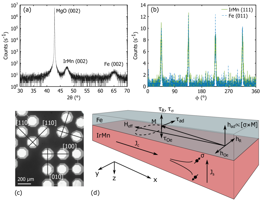
MgO / Fe(2, 3, 4) / (5) / Al(2) multilayers are sputtered on an MgO(001) substrate annealed at and before the deposition. Numbers in parentheses are layer thicknesses in nanometers. Composition of the IrMn is determined from thicknesses of Ir and Mn calibration films measured using X-ray reflectometry. The Fe and the IrMn are grown at . The protective Al layer is grown at . Typical growth rates are 0.1 - . The elevated deposition temperature and the small rate lead to epitaxial growth of Fe and IrMn, facilitated by the matching lattice parameter of the MgO substrate. X-ray diffraction is used to confirm the out-of-plane (001) order with a 2-rotation (Fig. 1(a)), whereas the in-plane four-fold symmetry is apparent from -rotations (Fig. 1(b)). Magnetic field of a few tens of mT is applied during growth to set the exchange bias. The measured exchange biases vary from to for different Fe thicknesses, confirming the antiferromagnetic order in all films.
Bars of width and length are fabricated using photolithography and ion milling (Fig. 1(c)). Contact pads of Cr(7) / Au(70) are thermally evaporated for wire bonding. One end of the bar is connected to a microwave transmission line, whereas the other end is grounded. Applied microwave current induces torques that drive the precession of the magnetization of Fe around the saturating magnetic field (Fig. 1(d)). Several field-like and (anti)damping-like torques can coexist in such bilayers. Examples of out-of-plane field-like torques are the Oersted torque , the interfacial Rashba spin-orbit torque Miron et al. (2010, 2011) and the field-like component of the spin-transfer torque due to the spin-Hall current from IrMn Liu et al. (2012). An in-plane (anti)damping-like component of the spin-transfer torque given by is also present in bilayers with heavy metals, and can be described by an out-of-plane field
| (1) |
We measure the current-induced magnetization precession as a rectified direct voltage due to the anisotropic magnetoresistance (AMR) Tulapurkar et al. (2005); Costache et al. (2006); Liu et al. (2011). Microwave frequency is kept constant while the magnetic field is varied in the plane of the film. The measured voltage can be decomposed into symmetric and antisymmetric Lorentzians centered at the ferromagnetic resonance field , so that
| (2) |
with magnitudes given by
| (3) | ||||
where is the current in the bar, is the AMR amplitude, and are coefficients determined by the magnetic anisotropies, and is the angle between the magnetization and current directions Tshitoyan (2016). The current-induced field is a combination of the earlier discussed effective fields shown in Fig. 1(d).
Ferromagnetic resonance measured in the Fe(4) / IrMn sample at is fitted to Eqn. 2 as shown in Fig. 2(a). For the used angle of , the positive means , because and (Eqn. 3). This is consistent with the Oersted field induced by the current in the IrMn (Fig. 1(d)). The negative sign of corresponds to because . Therefore
| (4) |
in contrast to previous measurements of positive spin-Hall angles in IrMn. Here, is the Fe thickness and is its saturation magnetization. The same measurement is repeated in a Fe(4) / Pt control sample and a positive symmetric component is observed (Fig. 2(b)), as expected for the positive spin-Hall angle of Pt.
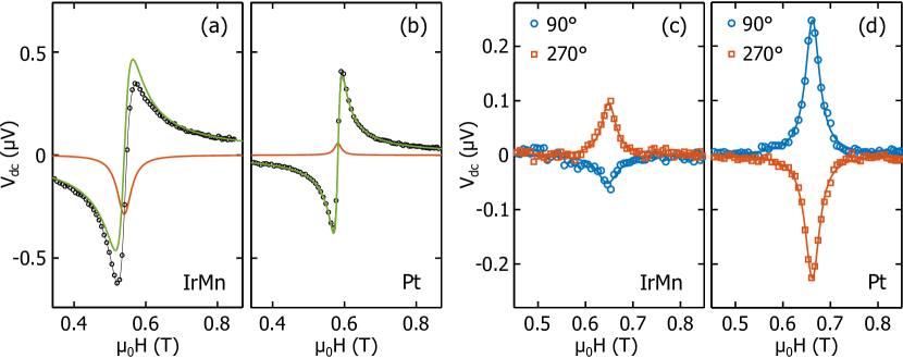
To confirm the opposite signs of the spin-Hall angles of Pt and the measured IrMn we perform spin-pumping measurements Saitoh et al. (2006); Mosendz et al. (2010); Tserkovnyak et al. (2005). The chip is placed on a microstrip transmission line and voltage is measured across a bar perpendicular to the line. The microwave field is in-plane along the bar, and the external field is applied perpendicular to the bar. Opposite signs of inverse spin-Hall voltages are measured in the IrMn and Pt samples (Fig. 2(c, d)), confirming the opposite spin-Hall angles.
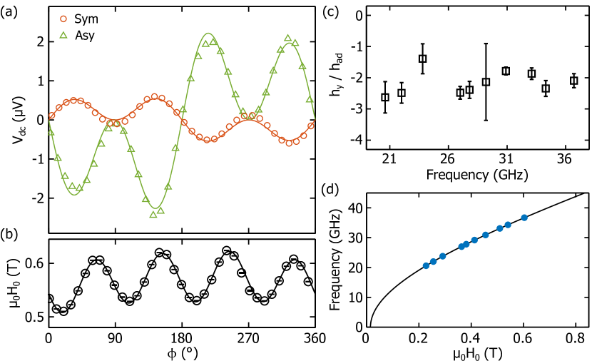
and for different angles in one of the Fe(4) / IrMn devices are plotted in Fig. 3(a). The symmetries are consistent with and an in-plane constant field , and are found to be independent on the crystallographic direction of the current. Strong cubic anisotropy of Fe as well as an exchange bias are measured (Fig. 3(b)), confirming the antiferromagnetic order in IrMn. The negative ratio shows no systematic variation across the studied frequency range (Fig. 3(c)) and the resonance frequency is described well by the Kittel mode with an effective magnetization of (Fig. 3(d)). This is slightly larger than the saturation magnetization of of bulk Fe Bayreuther and Lugert (1983), the value also measured in the Fe(4) / Pt control sample. The large value of could be due to a partial polarization of the uncompensated IrMn moments at the Fe / IrMn interface.
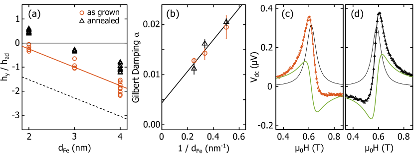
The negative spin-Hall angle of IrMn is confirmed in samples with 2 and Fe thicknesses. The ratios for 20 devices across different Fe thicknesses are shown with orange circles in Fig. 4(a). The spin-Hall angle can be calculated using Tshitoyan (2016)
| (5) |
where is the IrMn thickness and is the Fe / IrMn interface transparency, defined as the proportion of the induced spin-Hall current that is transferred into the ferromagnet. Although we cannot calculate the interface transparency T without the spin diffusion length and the conductivity of IrMn Tserkovnyak et al. (2002); Zhang et al. (2015b), we can confirm that it is approximately the same for the different Fe thicknesses. The effective spin-mixing conductance directly determining the interface transparency is given by
| (6) |
where is the Gilbert damping enhancement due to spin-pumping through the interface. In Fig. 4(b) we see that is inversely proportional to the Fe thickness, therefore is constant and the transparency does not vary substantially across the samples. We denote in further discussion.
Using
| (7) |
Eqn. 5 can be re-written as
| (8) |
where can be the interfacial Rashba field, the field-like term of the spin-Hall STT, or a combination of both. The solid orange line in Fig. 4(a) shows this ratio for and , matching well with the measurements. If we use , the values of average effective spin-Hall angles for the different Fe thicknesses would have to vary between ( Fe) and ( Fe) to explain the measurements. The order of magnitude difference is not realistic given the same interface transparency and the same thickness of the IrMn layer. The presence of substantial is further confirmed by annealing the samples at in Argon atmosphere. For the samples with Fe the antisymmetric Lorentzian, therefore also flip the sign (Fig. 4(c, d)). The new is opposite the Oersted field, which indicates presence of negative larger than the Oersted field Skinner et al. (2014). Values of after annealing are plotted with black triangles in Fig. 4(a). We note here that if we used the ratio to determine the spin-Hall angle, we would mistakenly conclude that after annealing the spin-Hall angle is large and positive in the samples with Fe.
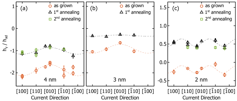
The ratios across different devices with the same Fe thickness vary by up to (Fig. 4(a)). Interestingly, these variations are not arbitrary and are correlated with the crystallographic direction of current. In Fig. 5(a - c) is plotted versus the direction of the bar it is measured in (Fig. 1(c)) for each Fe thickness. For the and Fe, a field along [100] was applied during growth, setting the exchange bias along that direction. We see that is larger for the current collinear with the exchange bias and smaller when perpendicular to it (Fig. 5(a, b)). The [100] and [010] directions are otherwise equivalent because of the cubic symmetry of both IrMn and Fe. In the Fe(3) / Pt control sample and are found for these bar directions, although the film is grown with the same magnetic field along [100]. This torque anisotropy, however, is not seen in the Fe film (Fig. 5(c)). The small variations of do not have an apparent uniaxial symmetry. Here, the field was applied along [10] during growth, resulting in an exchange bias along a direction between [010] and [10]. The misalignment could be due to [10] being an in-plane hard axis for Fe, so the field was not enough to fully align the magnetization.
We attempt to control the observed torque anisotropy by resetting the exchange bias. A field of is applied along different directions during annealing, successfully resetting the exchange bias after field cooling. The symmetry of , however, is not reset with the changing direction of the exchange bias as seen in Fig. 5.
The most important observation of our work is perhaps the negative spin-Hall angle. sputtered on Fe at the discussed conditions is chemically disordered Kohn et al. (2013). It is expected to have either the theoretically predicted multiple-Q spin density wave structure Sakuma et al. (2003), or the experimentally observed cubic-symmetry with moments tilted away by from crystal diagonals towards the cube faces Kohn et al. (2013). The latter is more likely when the crystal has in-plain strain, which is expected for IrMn grown on Fe. Previous measurements of positive spin-Hall angles have either considered polycrystalline IrMn or chemically ordered with the triangular magnetic structure. Zhang et al. measured a positive spin-Hall angle in polycrystalline Zhang et al. (2016), a composition very similar to our . Therefore, the exact crystalline and magnetic order is extremely important for spin-Hall effects in antiferromagnets. Similar conclusion was reached in several ab-initio studies for chemically ordered , suggesting that different current directions in the crystal can result in different magnitudes of spin-Hall angles, or even different signs Železný et al. (2017); Zhang et al. (2017, 2015a).
The second important observation is the large spin-orbit field with Rashba symmetry opposing the Oersted field that increases after annealing. Previous studies have found that the interfacial Rashba field due to inversion symmetry breaking is mostly reduced by annealing Garello et al. (2013); Avci et al. (2014). In contrast, if was due to the field-like component of the spin-transfer torque, its increase could be explained by the increased interface transparency after annealing. This would increase both and , effectively shifting up the ratio, in agreement with our observation (Fig. 4(a)). The negative sign of opposite the Oersted field is consistent with the negative spin-Hall angle of IrMn Fan et al. (2013); Kim et al. (2012).
Lastly, let us consider the anisotropy of the spin-orbit torques correlated with the initial direction of the exchange bias set during growth. Resetting the exchange bias along a different direction does not reset this anisotropy. Therefore, the bulk antiferromagnetic order in IrMn governing the exchange bias is unlikely to be the cause of the anisotropy. Moreover, exchange bias is the largest in the Fe sample which does not exhibit torque anisotropy correlated with the the exchange bias. Therefore, the anisotropy is not directly governed by the exchange bias. We believe the anisotropy is instead governed by uncompensated magnetic moments at the Fe / IrMn interface.
A possible explanation relies on differences of interface transparencies for different current directions. Assume that the magnetic field during growth creates uncompensated moments aligned with the field, which is [100] for 3 and Fe samples. Charge current along [100] creates spin-polarization along [010], which scatters at the uncompensated moments resulting in reduced transparency. Charge current along [010], in contrast, induces spin-polarization along [100] that scatters less at the interface, leading to a larger transparency. Hence, the observed larger for current along [010] compared to [100] (Fig. 5(a, b)). Field-cooling does not reorient the uncompensated moments, therefore the symmetry does not change. The variations are instead slightly reduced due to the reduction of the uncompensated moments at the elevated temperature. The absence of the anisotropy for the Fe sample could be due to the non-saturating field during growth leading to a more random orientation of the uncompensated moments.
In conclusion, we have observed a negative spin-Hall angle of a few percent in chemically disordered epitaxial , in contrast to previous measurements of large positive spin-Hall angles. This highlights the importance of the exact crystalline and magnetic structures for spin-Hall effects in antiferromagnets. A large spin-orbit field with Rashba symmetry opposing the Oersted field is also measured, which increases after thermal annealing. This observation shows that using effective field ratios in spin-torque FMR measurements can lead to wrong values and even a wrong sign for the spin-Hall angle. Lastly, magnitudes of spin-orbit torques depend on the direction of current with respect to the exchange bias set during growth. We believe this is governed by the uncompensated moments at the Fe / IrMn interface and is not directly correlated with the exchange bias or the antiferromagnetic order in bulk IrMn.
Authors would like to thank T. Jungwirth for his valuable comments. VT would like to thank the Winton Programme for the Physics of Sustainability and Cambridge Overseas Trust for financial support.
References
- Jungwirth et al. (2016) T. Jungwirth, X. Marti, P. Wadley, and J. Wunderlich, Nature Nanotechnology 11, 231 (2016).
- MacDonald and Tsoi (2011) A. H. MacDonald and M. Tsoi, Philosophical Transactions of the Royal Society A: Mathematical, Physical and Engineering Sciences 369, 3098 LP (2011).
- Wei et al. (2007) Z. Wei, A. Sharma, A. Nunez, P. Haney, R. Duine, J. Bass, A. MacDonald, and M. Tsoi, Physical Review Letters 98, 116603 (2007).
- Tang et al. (2007) X.-L. Tang, H.-W. Zhang, H. Su, Z.-Y. Zhong, and Y.-L. Jing, Applied Physics Letters 91, 122504 (2007).
- Urazhdin and Anthony (2007) S. Urazhdin and N. Anthony, Physical Review Letters 99, 046602 (2007).
- Moriyama et al. (2015a) T. Moriyama, N. Matsuzaki, K.-J. Kim, I. Suzuki, T. Taniyama, and T. Ono, Applied Physics Letters 107, 122403 (2015a).
- Wadley et al. (2016) P. Wadley, B. Howells, J. Zelezny, C. Andrews, V. Hills, R. P. Campion, V. Novak, K. Olejník, F. Maccherozzi, S. S. Dhesi, S. Y. Martin, T. Wagner, J. Wunderlich, F. Freimuth, Y. Mokrousov, J. Kunes, J. S. Chauhan, M. J. Grzybowski, A. W. Rushforth, K. W. Edmonds, B. L. Gallagher, and T. Jungwirth, Science 351, 587 (2016).
- Wang et al. (2014) H. Wang, C. Du, P. C. Hammel, and F. Yang, Physical Review Letters 113, 97202 (2014).
- Christian Hahn and Grégoire de Loubens and Vladimir V. Naletov and Jamal Ben Youssef and Olivier Klein and Michel Viret (2014) Christian Hahn and Grégoire de Loubens and Vladimir V. Naletov and Jamal Ben Youssef and Olivier Klein and Michel Viret, EPL (Europhysics Letters) 108, 57005 (2014).
- Moriyama et al. (2015b) T. Moriyama, S. Takei, M. Nagata, Y. Yoshimura, N. Matsuzaki, T. Terashima, Y. Tserkovnyak, and T. Ono, Applied Physics Letters 106, 162406 (2015b).
- Tshitoyan et al. (2015) V. Tshitoyan, C. Ciccarelli, A. P. Mihai, M. Ali, A. C. Irvine, T. A. Moore, T. Jungwirth, and A. J. Ferguson, Phys. Rev. B 92, 214406 (2015).
- Zhang et al. (2015a) W. Zhang, M. B. Jungfleisch, F. Freimuth, W. Jiang, J. Sklenar, J. E. Pearson, J. B. Ketterson, Y. Mokrousov, and A. Hoffmann, Physical Review B 92, 144405 (2015a).
- Reichlová et al. (2015) H. Reichlová, D. Kriegner, V. Holý, K. Olejník, V. Novák, M. Yamada, K. Miura, S. Ogawa, H. Takahashi, T. Jungwirth, and J. Wunderlich, Physical Review B 92, 165424 (2015).
- van den Brink et al. (2016) A. van den Brink, G. Vermijs, A. Solignac, J. Koo, J. T. Kohlhepp, H. J. M. Swagten, and B. Koopmans, Nature Communications 7, 10854 (2016).
- Kong et al. (2016) W. J. Kong, Y. R. Ji, X. Zhang, H. Wu, Q. T. Zhang, Z. H. Yuan, C. H. Wan, X. F. Han, T. Yu, K. Fukuda, H. Naganuma, and M.-J. Tung, Applied Physics Letters 109, 132402 (2016).
- Oh et al. (2016) Y.-W. Oh, S.-h. Chris Baek, Y. M. Kim, H. Y. Lee, K.-D. Lee, C.-G. Yang, E.-S. Park, K.-S. Lee, K.-W. Kim, G. Go, J.-R. Jeong, B.-C. Min, H.-W. Lee, K.-J. Lee, and B.-G. Park, Nature Nanotechnology 11, 878 (2016).
- Fukami et al. (2016) S. Fukami, C. Zhang, S. DuttaGupta, A. Kurenkov, and H. Ohno, Nature Materials 15, 535 (2016).
- Park et al. (2011) B. G. Park, J. Wunderlich, X. Martí, V. Holý, Y. Kurosaki, M. Yamada, H. Yamamoto, A. Nishide, J. Hayakawa, H. Takahashi, A. B. Shick, and T. Jungwirth, Nature materials 10, 347 (2011).
- Wang et al. (2012) Y. Y. Wang, C. Song, B. Cui, G. Y. Wang, F. Zeng, and F. Pan, Physical Review Letters 109, 137201 (2012).
- Marti et al. (2014) X. Marti, I. Fina, C. Frontera, J. Liu, P. Wadley, Q. He, R. J. Paull, J. D. Clarkson, J. Kudrnovský, I. Turek, J. Kuneš, D. Yi, J.-H. Chu, C. T. Nelson, L. You, E. Arenholz, S. Salahuddin, J. Fontcuberta, T. Jungwirth, and R. Ramesh, Nature Materials 13, 367 (2014).
- Fina et al. (2014) I. Fina, X. Marti, D. Yi, J. Liu, J. H. Chu, C. Rayan-Serrao, S. Suresha, A. B. Shick, J. Železný, T. Jungwirth, J. Fontcuberta, and R. Ramesh, Nature Communications 5, 4671 (2014).
- Kriegner et al. (2016) D. Kriegner, K. Výborný, K. Olejník, H. Reichlová, V. Novák, X. Marti, J. Gazquez, V. Saidl, P. Němec, V. V. Volobuev, G. Springholz, V. Holý, and T. Jungwirth, Nature Communications 7, 11623 (2016).
- Železný et al. (2017) J. Železný, Y. Zhang, C. Felser, and B. Yan, Physical Review Letters 119, 187204 (2017).
- Zhang et al. (2017) Y. Zhang, Y. Sun, H. Yang, J. Železný, S. P. P. Parkin, C. Felser, and B. Yan, Physical Review B 95, 75128 (2017).
- Zhang et al. (2014) W. Zhang, M. B. Jungfleisch, W. Jiang, J. E. Pearson, A. Hoffmann, F. Freimuth, and Y. Mokrousov, Physical Review Letters 113, 196602 (2014).
- Mendes et al. (2014) J. B. S. Mendes, R. O. Cunha, O. Alves Santos, P. R. T. Ribeiro, F. L. A. Machado, R. L. Rodríguez-Suárez, A. Azevedo, and S. M. Rezende, Physical Review B 89, 140406 (2014).
- Wu et al. (2016) D. Wu, G. Yu, C.-T. Chen, S. A. Razavi, Q. Shao, X. Li, B. Zhao, K. L. Wong, C. He, Z. Zhang, P. Khalili Amiri, and K. L. Wang, Applied Physics Letters 109, 222401 (2016).
- Zhang et al. (2016) W. Zhang, W. Han, S.-H. Yang, Y. Sun, Y. Zhang, B. Yan, and S. S. P. Parkin, Science Advances 2, e1600759 (2016).
- Yamaoka (1974) T. Yamaoka, Journal of the Physical Society of Japan 36, 445 (1974).
- Sakuma et al. (2003) A. Sakuma, K. Fukamichi, K. Sasao, and R. Umetsu, Physical Review B 67, 024420 (2003).
- Miron et al. (2010) I. M. Miron, G. Gaudin, S. Auffret, B. Rodmacq, A. Schuhl, S. Pizzini, J. Vogel, and P. Gambardella, Nature Materials 9, 230 (2010).
- Miron et al. (2011) I. M. Miron, K. Garello, G. Gaudin, P.-J. Zermatten, M. V. Costache, S. Auffret, S. Bandiera, B. Rodmacq, A. Schuhl, and P. Gambardella, Nature 476, 189 (2011).
- Liu et al. (2012) L. Liu, C.-F. Pai, Y. Li, H. W. Tseng, D. C. Ralph, and R. A. Buhrman, Science (New York, N.Y.) 336, 555 (2012).
- Tulapurkar et al. (2005) A. A. Tulapurkar, Y. Suzuki, A. Fukushima, H. Kubota, H. Maehara, K. Tsunekawa, D. D. Djayaprawira, N. Watanabe, and S. Yuasa, Nature 438, 339 (2005).
- Costache et al. (2006) M. V. Costache, S. M. Watts, M. Sladkov, C. H. van der Wal, and B. J. van Wees, Applied Physics Letters 89, 232115 (2006).
- Liu et al. (2011) L. Liu, T. Moriyama, D. C. Ralph, and R. A. Buhrman, Physical Review Letters 106, 36601 (2011).
- Tshitoyan (2016) V. Tshitoyan, Antiferromagnets for Spintronics, Ph.D. thesis, University of Cambridge (2016).
- Saitoh et al. (2006) E. Saitoh, M. Ueda, H. Miyajima, and G. Tatara, Applied Physics Letters 88, 182509 (2006).
- Mosendz et al. (2010) O. Mosendz, V. Vlaminck, J. E. Pearson, F. Y. Fradin, G. E. W. Bauer, S. D. Bader, and A. Hoffmann, Physical Review B 82, 214403 (2010).
- Tserkovnyak et al. (2005) Y. Tserkovnyak, A. Brataas, G. E. W. Bauer, and B. I. Halperin, Reviews of Modern Physics 77, 1375 (2005).
- Bayreuther and Lugert (1983) G. Bayreuther and G. Lugert, Journal of Magnetism and Magnetic Materials 35, 50 (1983).
- Kittel (1948) C. Kittel, Physical Review 73, 155 (1948).
- Tserkovnyak et al. (2002) Y. Tserkovnyak, A. Brataas, and G. E. W. Bauer, Physical Review B 66, 224403 (2002).
- Zhang et al. (2015b) W. Zhang, W. Han, X. Jiang, S.-H. Yang, and S. S. P. Parkin, Nature Physics 11, 496 (2015b).
- Skinner et al. (2014) T. D. Skinner, M. Wang, A. T. Hindmarch, A. W. Rushforth, A. C. Irvine, D. Heiss, H. Kurebayashi, and A. J. Ferguson, Applied Physics Letters 104, 062401 (2014).
- Kohn et al. (2013) A. Kohn, A. Kovács, R. Fan, G. J. McIntyre, R. C. C. Ward, and J. P. Goff, Scientific reports 3, 2412 (2013).
- Garello et al. (2013) K. Garello, I. M. Miron, C. O. Avci, F. Freimuth, Y. Mokrousov, S. Blügel, S. Auffret, O. Boulle, G. Gaudin, and P. Gambardella, Nature Nanotechnology 8, 587 (2013).
- Avci et al. (2014) C. O. Avci, K. Garello, C. Nistor, S. Godey, B. Ballesteros, A. Mugarza, A. Barla, M. Valvidares, E. Pellegrin, A. Ghosh, I. M. Miron, O. Boulle, S. Auffret, G. Gaudin, and P. Gambardella, Physical Review B 89, 214419 (2014).
- Fan et al. (2013) X. Fan, J. Wu, Y. Chen, M. J. Jerry, H. Zhang, and J. Q. Xiao, Nature Communications 4, 1799 (2013).
- Kim et al. (2012) J. Kim, J. Sinha, M. Hayashi, M. Yamanouchi, S. Fukami, T. Suzuki, S. Mitani, and H. Ohno, Nature Materials 12, 240 (2012).