Opposing effects of stacking faults and antisite domain boundaries on the conduction band edge in kesterite quaternary semiconductors
Abstract
We investigated stability and the electronic structure of extended defects including anti-site domain boundaries and stacking faults in the kesterite-structured semiconductors, Cu2ZnSnS4 (CZTS) and Cu2ZnSnSe4 (CZTSe). Our hybrid density functional theory calculations show that stacking faults in CZTS and CZTSe induce a higher conduction band edge than the bulk counterparts, and thus the stacking faults act as electron barriers. Antisite domain boundaries, however, accumulate electrons as the conduction band edge is reduced in energy, having an opposite role. An Ising model was constructed to account for the stability of stacking faults, which shows the nearest neighbour interaction is stronger in the case of the selenide.
Thin-film photovoltaic devices based on Cu2ZnSn(S,Se)4 (CZTSSe) absorber layers have attracted growing attention Polizzotti et al. (2013); Walsh et al. (2012); Wallace et al. (2017) as the materials are composed of Earth-abundant elements Schmalensee (2015), which are not categorised as Critical Raw Materials (CRM) by EU Eruopian Commission (2014). The system has a tuneable direct band gap of 1.01.5 eV Chen et al. (2009a), which is ideal for single junction solar cell applications Shockley and Queisser (1961). The certified solar conversion efficiency of 12.6% was achieved by an IBM group in 2013 Wang et al. (2014), and more recently, another group at DGIST achieved an efficiency of 12.3 % in 2016 by using a band-gap-graded absorber layer Yang et al. (2016).
Since current thin-film technologies mostly rely on polycrystalline materials, physical properties of extended defects, especially grain boundaries (GBs) have been investigated to understand their effects on the device efficiency Wang et al. (2011); Li et al. (2012); Mendis et al. (2012); Kim et al. (2014); Yin et al. (2014); Gershon et al. (2015); Liu et al. (2017). Other extended defects like stacking faults (SFs) and antisite domain boundaries (ADBs) have been less documented as compared to the GBs, but since SFs in CdTe act as electron barriers and reduce the efficiency Yan et al. (2001); Abbas et al. (2013); Sun et al. (2013); Yoo et al. (2014), SFs in CZTS should be investigated. There is also growing evidence that the materials have extended defects Song et al. (2015); Kattan et al. (2015, 2016). Formation of SFs was found in CZTS grown on single crystal Si (111) wafers Song et al. (2015) and CZTS nanoparticles Kattan et al. (2015). Another recent experimental study has shown that ADBs are formed abundantly in CZTS nanocrystals Kattan et al. (2016), possibly due to the low formation energy of antisite defect complexes in multi-component semiconductors Walsh et al. (2012). A density functional theory (DFT) calculation also shows that pre-existing defect complexes can lower the energy cost to form another defect complexes in close configuration Huang and Persson (2013), providing a hint that point defects can be gathered and form a spatially extended defect.
In this study, we investigate stability and the electronic structure of extended defects including SFs, ADBs, and the 3 (112) GB. We constructed an Ising model to account for the stability of SFs and examined an effect of broken symmetry at the boundary on the electronic structure. Our results show that the formation energy of SFs is small, while it is well explained by the Ising model. Change of the stacking orders raises the conduction band minimum (CBM) and thus the SFs generally act as electron barrier. On the other hand, the ADB with fault displacement induces several ten meV lower conduction band edge than the bulk counterpart, indicating that the defect could be a place where electrons are temporarily trapped.
We performed first-principles density functional theory (DFT) calculations to investigate physical properties of the extended defects. The hybrid functional proposed by Heyd, Scuseria, and Ernzerhof Heyd et al. (2003) as implemented in the VASP code was used Kresse and Furthmüller (1996). The projector-augmented wave (PAW) pseudo-potentials were used to describe the valence and core electron interactions Blöchl (1994). The screening parameter of 0.2 Å-1 and the exchange parameter of = 0.25 were used. The cutoff energy for the plane-wave basis was set to 400 eV. The lattice parameters and the internal coordinates were fully relaxed until the residual force becomes smaller than 0.03 eV Å-1. For Brillouin zone (BZ) integration, the smallest spacing between k-points was set to 0.05 Å-1.
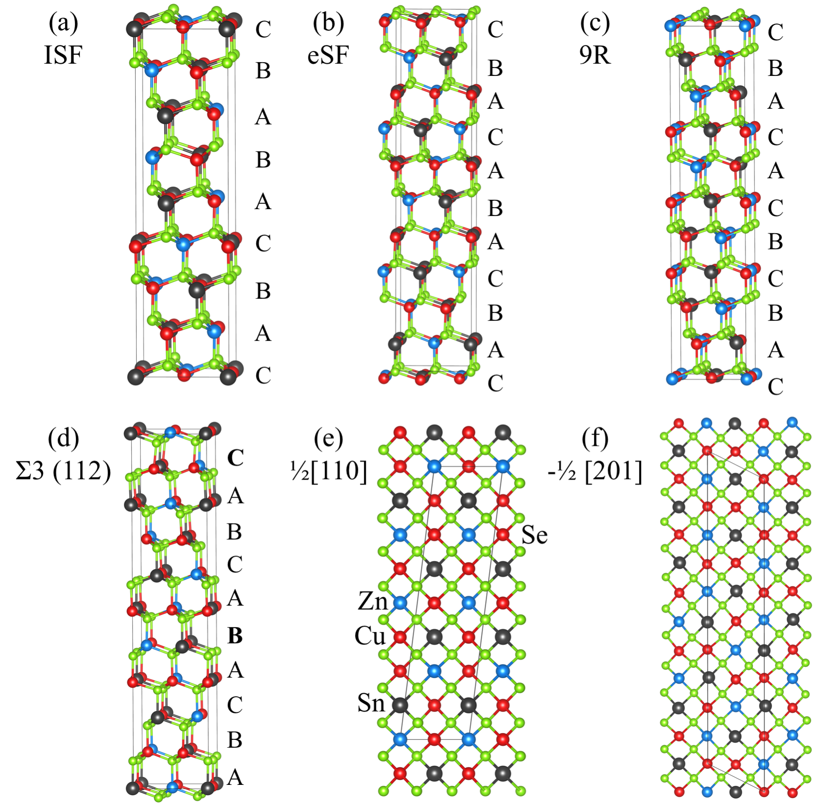
The atomic structure of SFs and the 3 (112) GB are shown in Figure 1. We note that each layer in the supercells has two Cu, one Zn, and one Sn atoms. Therefore, the position of the cations in an adjacent layer is determined when the Octet rule is preserved. Among various stacking faults, 9R, intrinsic stacking fault (ISF) and extrinsic stacking fault (eSF) were considered. The SFs has stacking sequences of (ABC/BCA/CAB), (ABC/BC/ABC), and (ABC/ABAC/ABC), respectively, as depicted in Figure 1, thus one can generate a supercell having a SF. On the other hand, a supercell having a 3 (112) GB contains two GBs because the 3 (112) GB has a layer with inversion symmetry at the middle of the cell (ABA). Another 3 (112) GB (e.g. ACA) is needed to restore the sequence order. Otherwise, a slab geometry should be pursued.
On the other hand, the ADBs can be represented by the accumulation of cation antisites in planes. Thus the Octet rule may or may not be satisfied at an ADB, depending on the fault displacement. For instance, Kattan et al. reported atomic structures of three ADBs, one satisfying the Octet rule and the others not satisfying the rule Kattan et al. (2016). Among them, we generated the atomic structures of ADBs with fault displacement of or , which are shown in Figure 1e and Figure 1f. Despite that the former is called an ADB, the Octet rule is not broken as its structure can be generated from kesterite by shifting a group of layers by (/2,/2,0) where is the lattice constant along and directions. As a result, narrow planes with Cu atoms are formed at the boundary. Such planes are also formed in primitive-mixed CuAu phases (PMCA), which another polytype of CZTS Chen et al. (2009a). Generally speaking, such faults in this category of materials results in higher formation energy and lower band gap, predicted by a previous first-principles calculation Park et al. (2015a). The Octet rule is broken at the other ADBs, and thus some S or Se atoms are bonded to 2 Sn atoms (The coordination in bulk kesterite is 1 Sn, 1 Zn, and 2 Cu).
To investigate the thermodynamic stability of the SFs and the 3 (112) GB, we constructed an Ising model following an approach which was used to understand polytypes of SiC Rutter and Heine (1997). Our Ising model for a supercell with layers is given by
| (1) |
where is the total energy of a given supercell. The energy of a single layer is given by , and represents the interaction energy between the th nearest neighbour layers ( = 1, 2, , M). An th layer can have either spin up () or spin down (), which is determined by comparison to the next layer (th layer). If two adjoining layers have AB, BC or CA stacking order, then the first layer has spin up. The two layers do not have the same letters (i.e. AA, BB and CC) in this study, and spin down is assigned to the th spin in remaining cases. Since we use periodic boundary conditions, , the total energy of bulk is equivalent to +++ per layer when is equal to 3.
The fitted parameters for SFs in CZTS are J1 = -20 meV/nm2, J2 = 0 meV/nm2 and J3 = 1 meV/nm2. On the other hand, those for SFs in CZTSe are J1 = -31 meV/nm2, J2 = 6 meV/nm2 and J3 = -3 meV/nm2. We don’t report because the absolute value of doesn’t have the physical meaning in our DFT calculation and the relative energy of SFs can be calculated without knowing . The strongest interaction parameters is significantly larger in CZTSe, indicating that SFs are less likely formed in CZTSe. This tendency is largely depicted in high formation energy of the wurtzite phase (2H) in CZTSe than CZTS, and also consistent with the anion rule that the zinc-blende phase becomes more favourable than the wurtzite phase as the anion size increases Yeh et al. (1992). Another difference between CZTS and CZTSe is smaller values of and , which results in the similar formation energy of 2H and 4H in CZTS.
Using the raw data obtained from DFT calculations and the Ising model, we calculated the formation energy of the extended defects. The formation energy of a SF, , is given by
| (2) |
where is the number of layers in a supercell and is a unit area of the SF. is total energy of bulk per unit cell (8 atoms). The formation energy obtained from DFT calculations () and that obtained from the Ising model () are summarised in Table 1. The difference between them is small enough to conclude that the formation energy of SFs is well explained by the Ising model. Stability of the two extreme cases, AB and ABCB, is well explained by the Ising model even though the two configurations were not considered to obtain the parameters . The calculated values of SFs and the GB are small, which is also consistent with other studies reporting the formation of SFs in other materials like Si and CdTe Chou et al. (1985); Käckell et al. (1998); Yan et al. (2001); Yoo et al. (2014); Park et al. (2015b).
To examine how the band edges are affected by the extended defects, we obtained averaged local potential given as
| (3) |
where is the interlayer distance. Band edges of pure CZTS or CZTSe were estimated using in a bulk-like region as a reference. The valence band offset (VBO) and the conduction band offset (CBO) between polytypes and the bulk counterparts are summarised in Table 1. There is no bulk-like region in (AB) and (ABCB), and thus the band offsets are not calculated. In both CZTS and CZTSe, the VBO is smaller than the room temperature energy. Therefore, we expect that it will not significantly affect the hole transport. On the other hand, the conduction band of the material with SFs are higher than that of the bulk counterpart, which is comparable to the room temperature thermal energy. This result clearly indicates that SFs act as electron barrier, making electron extraction difficult. It is generally accepted that SFs in zinc-blende structure (ABC) can be understood as a thin wurtzite layer (AB) surrounded by zinc-blende grains, and that results in electron barrier because of the type-II band offset between wurtzite and zinc-blende Murayama and Nakayama (1994); Yan et al. (2007), which is also found in the multi-component semiconductors. Our result is also consistent with the higher band gap of wurtzite-kesterite CZTS than kesterite CZTS and group theory analysis Chen et al. (2010).
The stability of ADBs suggested by an experimental study Kattan et al. (2016) were also investigated. It is worth emphasising that the suggested ADBs are formed only in multi-cation semiconductors as the ADBs are represented by cation disorder and thus don’t have anion-anion or cation-cation bonds. Supercell containing a ADB is stoichiometric, therefore the formation energy of the defect is simply calculated as defined above. is 0.23 eV/nm2 and 0.49 eV/nm2 in CZTS and CZTSe, respectively. Higher energy is required to form the ADB in CZTSe as compared to that in CZTS, indicating that the ADB is also less likely formed in CZTSe. On the electronic structure, the VBO between the ADB and bulk calculated using the potential alignments are negligible in both CZTS and CZTSe ( 3 meV). The CBO, on the other hand, is -70 meV and -77 meV, respectively, indicating that the ADBs can easily trap electrons, which is opposite to the SFs.
This opposite effect of the ADB on the conduction band is consistent with a previous DFT calculation with symmetry analysis Park et al. (2015a). The ADB, a polytype with infinite length, has the similar atomic structure to PMCA in a local sense as both have Cu layers, while the faults increase the formation energy of polytype as shown in a previous study Park et al. (2015a). The electronic band gap of the polytype is negative-linearly correlated with the formation energy of polytypes Park et al. (2015a), and thus the ADB should lower the band gap. Moreover, as it has been shown that the kesterite, stannite, and PMCA Cu2ZnGeS4 have similar valence band edge position, and change of the band gap is mainly explained by change of the conduction band Chen et al. (2009b). Since the ADB can be regarded as high energy polytype in a local sense, the ADB is expected to have lower conduction band edge than bulk, which is found in our calculation. We note that the band offset due to the ADB is similar to the band gap fluctuations in real samples (0.05-0.15 eV) Bishop et al. (2017); Gokmen et al. (2013), indicating that the VOC deficit can be at least partly explained by the formation of the ADBs.
Experimental evidence of faults in the layer with Cu and Sn has been provided Kattan et al. (2016), however, Cu and Zn are difficult to distinguish by transmission electron microscope (TEM). Due to the larger chemical (size and charge) mismatch, the layer with Cu and Sn should be more rigid than the layer with Cu and Zn. But the effect of Cu-Zn disorder on the electronic structure should be less than 0.04 eV according to the DFT calculation Chen et al. (2009b). We also examined whether ZnCu+CuZn at the ADB affects the conclusion, but it changes the band edge position only marginally ( 3 meV).
The supercell model for the ADB with fault (Figure 1f) contains more Zn and Sn atoms as compared to bulk, and thus the boundary can be understood as segregation of SnCu and a ZnCu defects. Relaxation of internal coordinates for the supercell model using HSE06 functional is too computationally demanding, therefore, we relaxed the structure using the SCAN Sun et al. (2015) functional applying on-site Coulomb potential of 6 eV on Cu d and Zn d. Self-consistent field (SCF) calculations using HSE06 functional were subsequently performed to analyse the electronic structure.
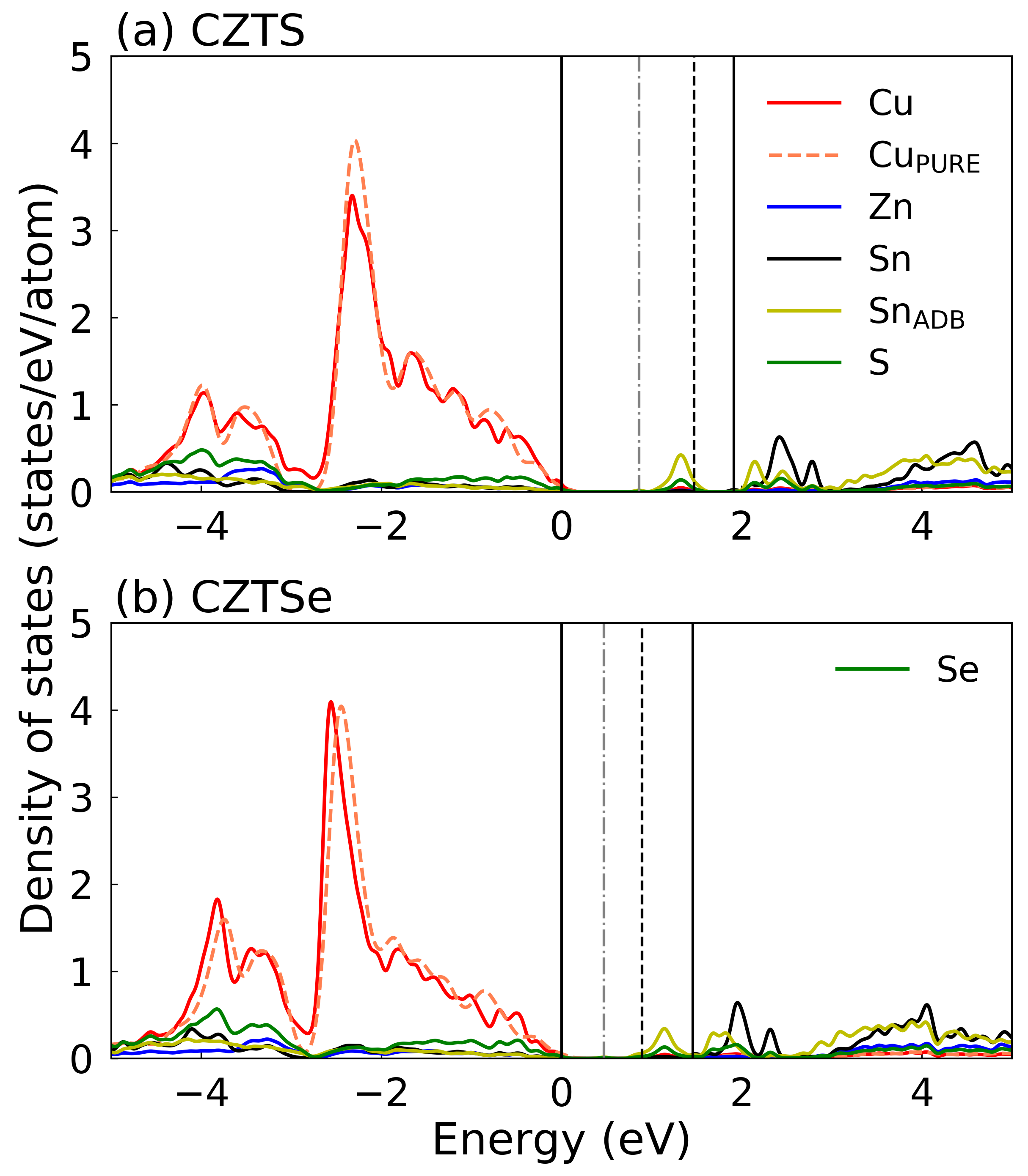
The calculated projected density of states (PDOS) of the ADB in CZTS and CZTSe with fault are shown in Figure 2. We find that Sn atoms at the boundary introduce gap states, which are mainly composed of Sn s and S (Se) p anti-bonding character. Our supercell is not large enough to reproduce the bulk band gap, however, we expect that the band gap is widened in the supercell because of the raised conduction band resulting from the quantum confinement effect. Consistent with our expectation, the PDOS of Cu in bulk CZTS fits well with that in the supercell. In CZTSe, peak positions are slightly shifted ( 0.1 eV), but doesn’t affect the conclusion that the ADB introduces the gap states as the lowest defect state is higher than the valence band maximum by 0.52 eV, close to the middle of the band gap. The gap states are delocalized in the boundary, indicating that charge carriers trapped by the state will conduct in the boundary.
A post-deposition annealing treatment (e.g. using CdCl2) is necessary to improve the CdTe solar cells Major et al. (2014). There are many competing explanations on the beneficial effect of the treatment Dharmadasa (2014), and recent studies also show that one effect of the treatment is the removal of the SFs Abbas et al. (2013); Yoo et al. (2014). A SF in CdTe can be regarded as a buried wurtzite phase which has higher conduction band than the zinc-blende CdTe, and thus it is expected to act as an electron barrier Wei and Zhang (2000). It was recently found in an experimental study that the conductivity along the direction normal to the SFs is suppressed because of the band offset Sun et al. (2013). Since the SFs in the kesterite-structured materials also act as electron barriers, a similar annealing process should be pursued to remove the extended defects from the absorber layer.
Finally, we point out that the electrical property of the SFs can be qualitatively estimated as discussed above by comparing the band edges of polymorphs, and this working principle is not limited to zinc-blende and zinc-blende derived structures. For instance, previous DFT calculations show that wurtzite ZnO and III-nitrides have higher conduction band than their zinc-blende counterparts, and thus the SFs lower the conduction bands and act as electron sinks, not barriers as in CZTS Yan et al. (2004); Stampfl and Van de Walle (1998).
In summary, we investigated the thermodynamic stability and the electronic structure of extended defects in the multi-cation semiconductors, CZTS and CZTSe. Formation energy of extended defects in CZTS and CZTSe were calculated by performing hybrid density functional theory calculations. Since less energy is required to form SFs than the ADBs, SFs are more likely formed in the multi-cation semiconductors. An Ising model was successfully constructed to account for their stability, and the interaction between two adjacent layers is fitted to be stronger than the other interactions between layers. The SFs and the ADBs satisfying the Octet rule introduce higher and lower conduction band than the bulk region, acting as electron barrier and sink, respectively. The ADB not satisfying the Octet rule, on the other hand, introduces deep gap states. Compared to the electron transport, the hole transport is less affected by the extended defects. Our computational results indicate that extended defects slightly favoured in CZTS as compared to CZTSe, potentially results in larger variation of the conduction band edge. Annealing procedures used for other technologies (e.g. CdCl2 for CdTe) could be applied to the kesterite solar cells.
Acknowledgements.
This project has received funding from the European H2020 Framework Programme for research, technological development and demonstration under grant agreement no. 720907. See http://www.starcell.eu. AW is supported by a Royal Society University Research Fellowship. Via our membership of the UK’s HPC Materials Chemistry Consortium, which is funded by EPSRC (EP/L000202), this work used the ARCHER UK National Supercomputing Service (http://www.archer.ac.uk). We are grateful to the UK Materials and Molecular Modelling Hub for computational resources, which is partially funded by EPSRC (EP/P020194/1).References
- Polizzotti et al. (2013) A. Polizzotti, I. L. Repins, R. Noufi, S.-H. Wei, and D. B. Mitzi, Energy & Environ. Sci. 6, 3171 (2013).
- Walsh et al. (2012) A. Walsh, S. Chen, S.-H. Wei, and X.-G. Gong, Adv. Energy Mater. 2, 400 (2012).
- Wallace et al. (2017) S. K. Wallace, D. B. Mitzi, and A. Walsh, Adv. Mater. 2, 776 (2017).
- Schmalensee (2015) R. Schmalensee, The Future of Solar Energy: An Interdisciplinary MIT Study (Energy Initiative, Massachusetts Institute of Technology, 2015).
- Eruopian Commission (2014) Eruopian Commission, Report on Critical Raw materials for the EU (2014).
- Chen et al. (2009a) S. Chen, X. Gong, A. Walsh, and S.-H. Wei, Appl. Phys. Lett. 94, 041903 (2009a).
- Shockley and Queisser (1961) W. Shockley and H. J. Queisser, J. Appl. Phys. 32, 510 (1961).
- Wang et al. (2014) W. Wang, M. T. Winkler, O. Gunawan, T. Gokmen, T. K. Todorov, Y. Zhu, and D. B. Mitzi, Adv. Energy Mater. 4, 1301465 (2014).
- Yang et al. (2016) K.-J. Yang, D.-H. Son, S.-J. Sung, J.-H. Sim, Y.-I. Kim, S.-N. Park, D.-H. Jeon, J. Kim, D.-K. Hwang, C.-W. Jeon, D. Nam, H. Cheong, J.-K. Kang, and D.-H. Kim, J. Mater. Chem. A 4, 10151 (2016).
- Wang et al. (2011) K. Wang, B. Shin, K. B. Reuter, T. Todorov, D. B. Mitzi, and S. Guha, Appl. Phys. Lett. 98, 051912 (2011).
- Li et al. (2012) J. B. Li, V. Chawla, and B. M. Clemens, Adv. Mater. 24, 720 (2012).
- Mendis et al. (2012) B. G. Mendis, M. C. Goodman, J. D. Major, A. A. Taylor, K. Durose, and D. P. Halliday, J. Appl. Phys. 112, 124508 (2012).
- Kim et al. (2014) G. Y. Kim, A. R. Jeong, J. R. Kim, W. Jo, D.-H. Son, D.-H. Kim, and J.-K. Kang, Sol. Energ. Mat. Sol. C. 127, 129 (2014).
- Yin et al. (2014) W.-J. Yin, Y. Wu, S.-H. Wei, R. Noufi, M. M. Al-Jassim, and Y. Yan, Adv. Energy Mater. 4, 1300712 (2014).
- Gershon et al. (2015) T. Gershon, B. Shin, N. Bojarczuk, M. Hopstaken, D. B. Mitzi, and S. Guha, Adv. Energy Mater. 5, 1400849 (2015).
- Liu et al. (2017) C.-Y. Liu, Z.-M. Li, H.-Y. Gu, S.-Y. Chen, H. Xiang, and X.-G. Gong, Adv. Energy Mater. 7, 1601457 (2017).
- Yan et al. (2001) Y. Yan, M. M. Al-Jassim, and T. Demuth, J. Appl. Phys. 90, 3952 (2001).
- Abbas et al. (2013) A. Abbas, G. D. West, J. W. Bowers, P. Isherwood, P. M. Kaminski, B. Maniscalco, P. Rowley, J. M. Walls, K. Barricklow, W. S. Sampath, and K. L. Barth, IEEE J. of Photovoltaics 3, 1361 (2013).
- Sun et al. (2013) C. Sun, N. Lu, J. Wang, J. Lee, X. Peng, R. F. Klie, and M. J. Kim, Applied Physics Letters 103, 252104 (2013).
- Yoo et al. (2014) S.-H. Yoo, K. T. Butler, A. Soon, A. Abbas, J. M. Walls, and A. Walsh, Appl. Phys. Lett. 105, 062104 (2014).
- Song et al. (2015) N. Song, M. Young, F. Liu, P. Erslev, S. Wilson, S. P. Harvey, G. Teeter, Y. Huang, X. Hao, and M. A. Green, Appl. Phys. Lett. 106, 252102 (2015).
- Kattan et al. (2015) N. Kattan, B. Hou, D. J. Fermín, and D. Cherns, Applied Materials Today 1, 52 (2015).
- Kattan et al. (2016) N. Kattan, I. Griffiths, D. Cherns, and D. Fermín, Nanoscale 8, 14369 (2016).
- Huang and Persson (2013) D. Huang and C. Persson, Thin Solid Films 535, 265 (2013).
- Heyd et al. (2003) J. Heyd, G. E. Scuseria, and M. Ernzerhof, The Journal of Chemical Physics 118, 8207 (2003).
- Kresse and Furthmüller (1996) G. Kresse and J. Furthmüller, Phys. Rev. B 54, 11169 (1996).
- Blöchl (1994) P. E. Blöchl, Phys. Rev. B 50, 17953 (1994).
- Park et al. (2015a) J.-S. Park, J.-H. Yang, A. Kanevce, S. Choi, I. L. Repins, and S.-H. Wei, Phys. Rev. B 91, 075204 (2015a).
- Rutter and Heine (1997) M. Rutter and V. Heine, J. Phys.: Condens. Matter 9, 8213 (1997).
- Yeh et al. (1992) C.-Y. Yeh, Z. W. Lu, S. Froyen, and A. Zunger, Phys. Rev. B 46, 10086 (1992).
- Chou et al. (1985) M. Y. Chou, M. L. Cohen, and S. G. Louie, Phys. Rev. B 32, 7979 (1985).
- Käckell et al. (1998) P. Käckell, J. Furthmüller, and F. Bechstedt, Phys. Rev. B 58, 1326 (1998).
- Park et al. (2015b) J.-S. Park, J. Kang, J.-H. Yang, W. Metzger, and S.-H. Wei, New J. Phys. 17, 013027 (2015b).
- Murayama and Nakayama (1994) M. Murayama and T. Nakayama, Phys. Rev. B 49, 4710 (1994).
- Yan et al. (2007) Y. Yan, K. Jones, C. Jiang, X. Wu, R. Noufi, and M. Al-Jassim, Physica B 401, 25 (2007).
- Chen et al. (2010) S. Chen, A. Walsh, Y. Luo, J.-H. Yang, X. Gong, and S.-H. Wei, Phys. Rev. B 82, 195203 (2010).
- Chen et al. (2009b) S. Chen, X. G. Gong, A. Walsh, and S.-H. Wei, Phys. Rev. B 79, 165211 (2009b).
- Bishop et al. (2017) D. M. Bishop, B. McCandless, T. Gershon, M. A. Lloyd, R. Haight, and R. Birkmire, J. Appl. Phys. 121, 065704 (2017).
- Gokmen et al. (2013) T. Gokmen, O. Gunawan, T. K. Todorov, and D. B. Mitzi, Appl. Phys. Lett. 103, 103506 (2013).
- Sun et al. (2015) J. Sun, A. Ruzsinszky, and J. P. Perdew, Phys. Rev. Lett. 115, 036402 (2015).
- Major et al. (2014) J. D. Major, R. E. Treharne, L. J. Phillips, and K. Durose, Nature 511, 334 (2014).
- Dharmadasa (2014) I. Dharmadasa, Coatings 4, 282 (2014).
- Wei and Zhang (2000) S.-H. Wei and S. B. Zhang, Phys. Rev. B 62, 6944 (2000).
- Yan et al. (2004) Y. Yan, G. Dalpian, M. Al-Jassim, and S.-H. Wei, Physical Review B 70, 193206 (2004).
- Stampfl and Van de Walle (1998) C. Stampfl and C. G. Van de Walle, Physical Review B 57, R15052 (1998).
| Stacking | VBO (meV) | CBO (meV) | ||
|---|---|---|---|---|
| ISF | 0.14 (0.18) | 0.15 (0.20) | 6 (9) | 28 (29) |
| eSF | 0.14 (0.16) | 0.15 (0.17) | 6 (5) | 28 (25) |
| 9R | 0.31 (0.37) | 0.31 (0.37) | -2 (11) | 32 (48) |
| 3 (112) | 0.07 (0.10) | 0.07 (0.10) | -15 (-5) | 16 (18) |
| 2H (AB) | 0.17 (0.25) | 0.15 (0.24) | ||
| 4H (ABCB) | 0.15 (0.17) | 0.15 (0.15) |