∎
22email: {mateos, vinze}@acin.tuwien.ac.at
LaMMos - Latching Mechanism based on Motorized-screw for Reconfigurable Robots and Exoskeleton Suits
Abstract
Reconfigurable robots refer to a category of robots that their components (individual joints and links) can be assembled in multiple configurations and geometries. Most of existing latching mechanisms are based on physical tools such as hooks, cages or magnets, which limit the payload capacity. Therefore, robots require a latching mechanism which can help to reconfigure itself without sacrificing the payload capability.
This paper presents a latching mechanism based on the flexible screw attaching principle. In which, actuators are used to move the robot links and joints while connecting them with a motorized-screw and disconnecting them by unfastening the screw. The brackets used in our mechanism configuration helps to hold maximum force up to . The LaMMos - Latching Mechanism based on Motorized- screw has been applied to the DeWaLoP - Developing Water Loss Prevention in-pipe robot. It helps the robot to shrink its body to crawl into the pipe with minimum diameter, by reconfiguring the leg positions. And it helps to recover the legs positions to original status once the robot is inside the pipe. Also, LaMMos add stiffness to the robot legs by dynamically integrate them to the structure.
Additionally, we present an application of the LaMMos mechanism to exoskeleton suits, for easing the motors from the joints when carrying heavy weights for long periods of time.
This mechanism offers many interesting opportunities for robotics research in terms of functionality, payload and size.
Keywords:
Reconfigurable Robot Latching Mechanism In-pipe Robots Exoskeleton Suits1 INTRODUCTION
In order to be better adapted to various sized targets or complex geometric requirements, it is desirable that robots used in modern mechanical systems are geometrically reconfigurable. It means that the topological structure, kinematic parameters or dynamic parameters of the mechanism may be adjustable during the motion process 5173816 . A reconfigurable robot consists of a collection of individual links and joint components that can be assembled into multiple robot geometries. Compared to a conventional industrial robot with fixed geometry, such a system is able to provide flexibility, enabling itself to cope with a wide spectrum of tasks through proper selection and reconfiguration of a large inventory of functional components conro .
Additionally, to the geometrical adjustment, in some cases, it is expected that the robot become stronger if it reconfigures its structure in order to carry loads beyond its initial capability or maintain its position passively and not actively consuming energy from the actuators.
Commonly, these reconfigurable mechanisms join the robot links with a latching mechanism, such as hooks, cages or magnets crossball Superbot Miche singo . In this way, the mechanism is fast to attach and flexible to connect. However, it has the limitation of restricting the payload capacity.
One can categorize them into two types, magnetic latching and physical latching.
Magnetic latching
Miche (Modular Shape Formation by Self-Disassembly) Miche includes a connection mechanism by switchable magnets, able to connect to a neighbor s steel plate and can support . A similar latching mechanism is the M-TRAN (Self-Reconfigurable Modular Robotic System) mtran , which is composed of nonlinear springs, Shape Memory Alloy (SMA) coils and magnets fixed on a moving part (connecting plate), able to lift two modules within the actual torque limit (-).
As a result, the payload supported by these magnetics latching mechanism is relatively low if compared to physical latching connection mechanism.
Physical latching
A. Sproewitz 4543747 presents a robust and heavy duty physical latching connection mechanism, which can ben seen as a hook with clamping principles. It can be actuated with DC motors to actively connect and disconnect modular robot units with load up to .
Similar, the Superbot Superbot module consists of six connectors, one on each side of the end effectors. Any of the six connectors of the Superbot module can connect to any connectors of another module with orientation intervals of 90∘. The module’s drivetrain for each degree-of-freedom (DOF) includes a DC electric motor, a planetary gearbox, and an external gearbox, resulting in a maximum of torque. Given the size and weight of each module, this amount of torque is enough for reliably lifting three neighboring modules.
JL-1 5173891 is a reconfigurable multi-robots system based on parallel and cone-shaped docking mechanisms. It is used for joining mobile robots to each other, in order to adopt a reconfigurable chain structure to cope with the cragged landforms which are difficult to overcome for a single robot. Therefore, when two robots are linked, a full motorized spherical joint is formed. This mechanism requires two motors on the docking side and one more motor on the driving platform connection.
In contrast to the presented state of the art in latching mechanism, the LaMMos - Latching Mechanism based on Motorized-screw mechanism is able to support payloads up to and requires only one motor to make connection.
This paper describes the design and development of the LaMMos mechanism. Additionally, a couple of applications are presented, one for the DeWaLoP in-pipe robot and another for exoskeleton suits.
For the DeWaLoP in-pipe robot, the LaMMos mechanism helps the robot to shrink its body to crawl into the pipe with minimum diameter, by reconfiguring the leg positions. And it helps to recover the legs positions as original once the robot is inside the pipe. Also, the LaMMos mechanism is used for increase the stiffness of the robot legs by dynamically integrate them to the structure.
Another application of the LaMMos mechanism following the same principle of creating a rigid structure from movable joints is for exoskeleton suits 4058569 6650376 4291584 . The LaMMos can improve the payload capacity of exoskeletons when these are required to carry heavy weights for long periods of time.
2 Requirements for a latching mechanism in reconfigurable robot
The aim of docking mechanism in reconfigurable robots is to attach/detach robot modules. There are a few requirements that a latching mechanism should fulfill intro crossball Superbot Miche . However, the relevance of each single feature differs, depending on the functionality of the robot itself. Here we list the common requirements for a docking or connection mechanism used in self reconfiguration robots.
- Simple and fast docking procedure
- Symmetric
- Genderless
- No accidental latching
- Small size and durable
- No power consumption in static state
- Reliable power and signal transfer
- Stable connection
- Integration and protection of sensors
- High latch load and impact strength
- Few parts (especially moving ones)
- Easy maintenance
- Easy and low cost manufacturing and assembling
The integration of all required features into a single functional mechanism is challenging and should be adapted to the purpose of the robot. All mentioned features can be implemented into LaMMos mechanism except the genderless ability. This feature is important for modular robots. Due that modules must be able to lock/unlock in any position. However, LaMMos is intended only for self-reconfigurable robot with predefined locking points.
3 LaMMos Mechanism
The LaMMos mechanisms enables robots to reconfigure its structure without loosing its payload capacity as other common latching mechanisms do. Also, the LaMMos mechanism enable robot joints to become rigid within its structure in order to handle heavy weight loads for long periods of time without loosing energy and protecting its movable actuators.
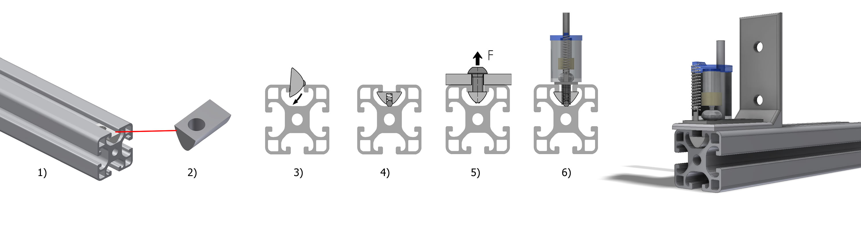
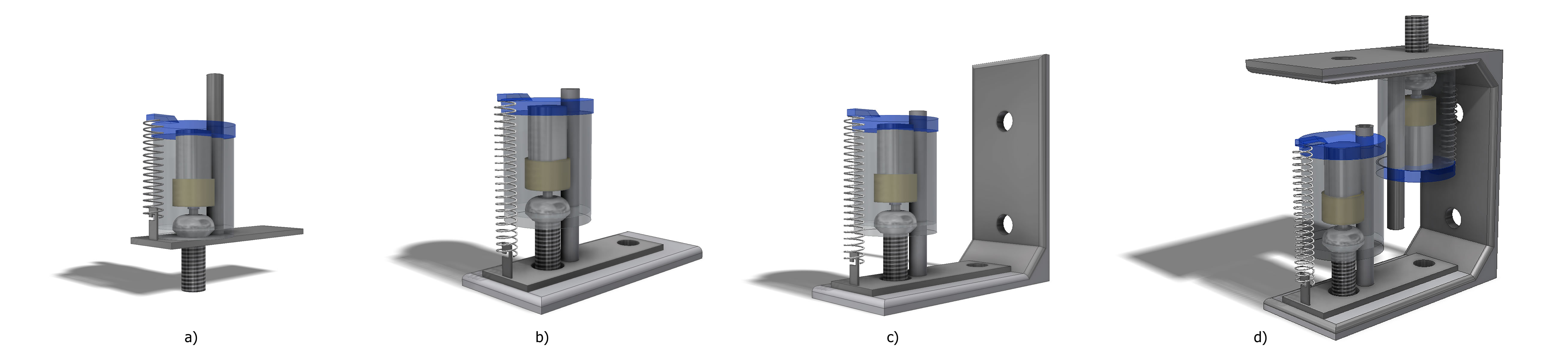
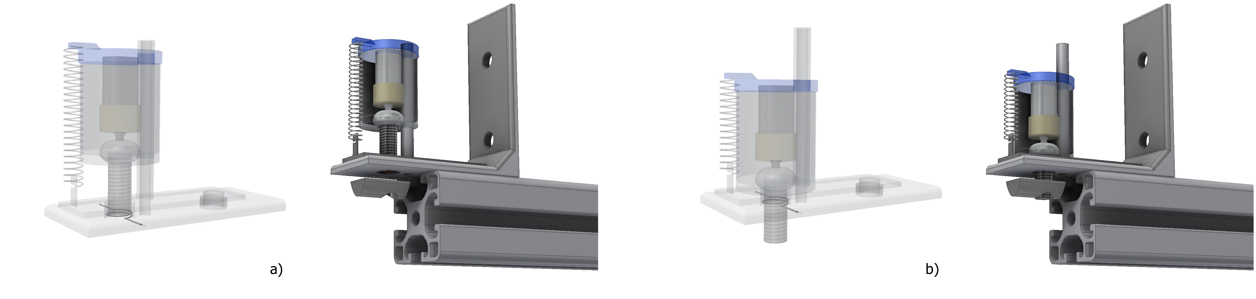
The LaMMos mechanism adopts the flexible screw attaching principle for connecting or disconnecting robot parts. It can be applied to any robots having rigid materialized surface, such as aluminum profiles, in which a T-Slot nut can be locked for further connection with brackets, as shown in Fig. 1. Moreover, LaMMos can be included in any type of bracket, such as flat, right angle, box, etc. Also, multiple LaMMos can be included in the same bracket, see Fig. 4.
The LaMMos mechanism mimics the human operation of constructing robot links on the robot body by tightening a screw over a nut inside the body, and deconstructing the robot links by driving the screw out of the body.
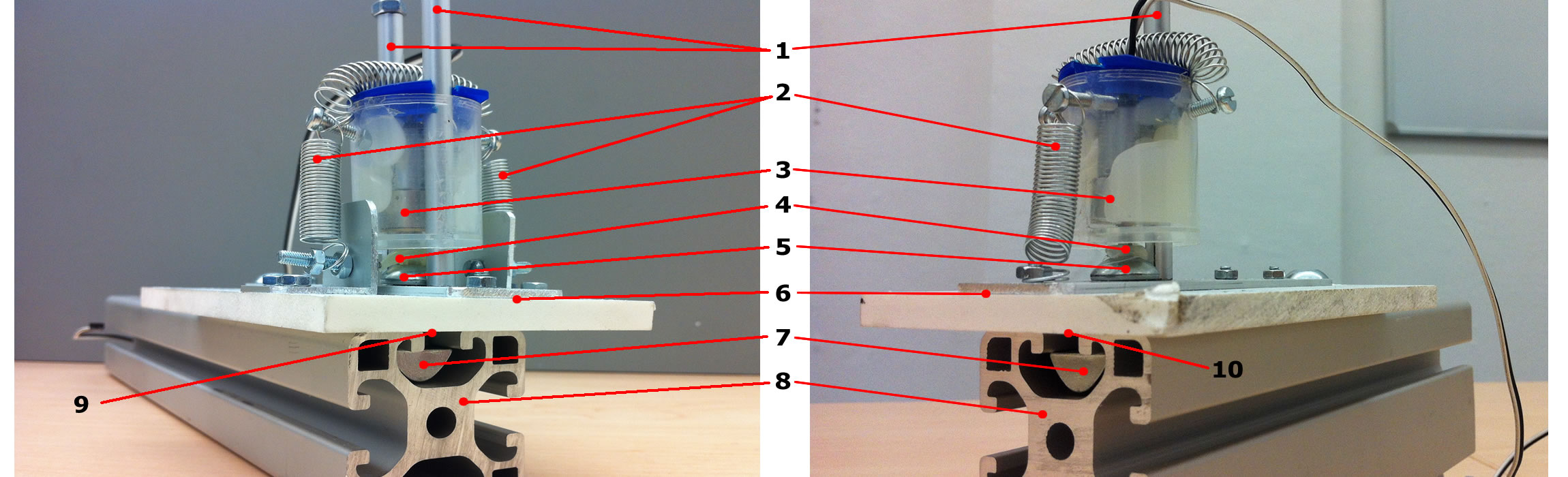
The main constituting elements of the LaMMos mechanism are divided into two main parts, the active part and passive part. The active part includes all the elements around the bracket: geared motor, screw, flexible nut, a compressed springs, a guiding tube and the bracket itself, as shown in Fig. 2. The passive part is the T-slot nut inserted into the robot body, or any device inside of the robot body that provide a nut for the screw.
The presented LaMMos mechanism is a simplified version of the standard LaMMos mechanism Ref:DeWaLoP_ICAR2013 . The main differences between these two versions are in the guiding mechanism. Since the motorized-screw is the same.
In the standard LaMMos version, the guiding mechanism includes a couple of compressed springs, two guiding rails and a moldable rubber inside the hole of the bracket. Whereas, in the simplified LaMMos, the guiding mechanism includes only one compressed spring, one guiding rail and a spring acting as a flexible nut located inside the hole of the bracket for guiding the motorized-screw.
T-Slot nut
The T-Slot nut is used for securing heavy components in fastening applications.
The T-Slot nuts are inserted into the profile groove where they are secured in position by driving a screw into it.
It will stay secure with holding up maximum force up to , as shown in Fig. 1.
Driving mechanism - motorized-screw
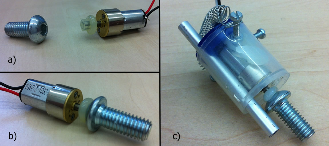
The driving mechanism consists of a micro-geared motor with an integrated screw.
The geared motor specifications are in table 1.
The screw is an hexagonal head with a length of . A plastic resin is modeled to join the geared motor with the screw. It fits the motor shaft and the hexagonal screw head, as shown in Fig. 3 and Fig. 3.
The geared motor is encapsulated in a cylinder with radius of and length of height of . The capsule includes a hole for the guiding system of the motorized-screw.
| Dimensions | length = |
|---|---|
| width = | |
| height = | |
| Gear ration | 298:1 |
| Stall Torque | at |
| at | |
| Shaft | diameter shaped |
Guiding mechanism
The guiding mechanism of the simplified LaMMos consists of a single aluminum tube attached to the bracket, with diameter of and length of . The tube crosses the cylinder where the geared motor is encapsulated, becoming its guiding rail in conjunction with the motorized-screw, as shown in Fig. 3.
In addition, the LaMMos mechanism includes a compressed spring with length of and width of with side hooks, see Table 2. The function of the springs is to maintain the geared motor in touch with the bracket base when it tries to get out of it by rotating counterclockwise (unscrewing). In other words, the springs act as a pushing force for the motorized-screw to maintain its position when the screw gets loose.
| Dimensions | length = |
|---|---|
| width = | |
| Diameter of spring wire, | |
| Number of active coils, | |
| Material | Stainless steel |
| Weight | |
| Maximum load |
Flexible nut
A flexible nut is located inside the hole of the bracket.
Physically the flexible nut is similar to a torsion spring, it consists of a spring with one coil and with two opposite extension of the spring wires, which are inserted into the LaMMos bracket, as shown in figure 5.
The coil diameter is set to the diameter of the screw and the diameter of the wire is half millimeter diameter, so the thread of the screw is trapped.
In the previous LaMMos mechanisms the flexible nut functionality was done by a moldable rubber. However, the moldable rubber can wear out over time.
Since the functionality of the flexible nut is to guide the screw up or down from the bracket hole.
In this way, the flexible nut acts in two different ways:
housing the screw and guiding the screw.
Housing the screw
In order to move the LaMMos bracket, the screw must be housed in unlatching status, preventing any accidental latching.
The screw is always pushed by the compressed springs towards the bracket, in order to maintain it over the bracket. With the friction provided by the flexible nut, the screw will not go straight through the bracket causing accidental latching, as shown in Fig. 5. In this mode, the LaMMos is set as a movable part.
Guiding the screw to the T-Slot nut
During the latching process, the flexible nut provides an initial thread inside the bracket for the screw to go through until it reaches the T-slot nut inside the fastening target (robot body). The flexible nut has the property of guiding thread, so that the screw will not be stopped and tight with it before it reaches the T-slot, as shown in Fig. 5.
Next, we introduce the DeWaLoP in-pipe robot and recall the multiple use of LaMMos mechanism in the robot.
4 DeWaLoP In-PIPE ROBOT
DeWaLoP stands for Developing Water Loss Prevention. The goal of the DeWaLoP robot is to restore (repair, clean, etc,.) the over 100 years old pipe-joints of the fresh water supply systems of Vienna and Bratislava. These pipelines range from to diameters and are still in good metallurgical shape. The pipe-joints have been detected as water loss points and therefore the DeWaLoP robot system is intended to crawl into these pipes and restore them Ref:MA31 .
The DeWaLoP robot has large scale in size and weight. It has length of 1.4 meters and radius of , with weight from .
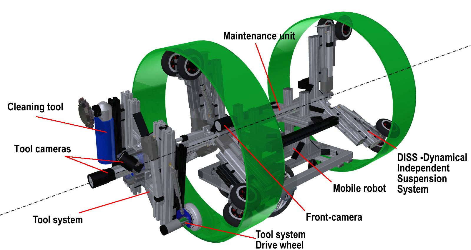
The robot consists of five main subsystems: control station, mobile robot, maintenance system, vision system and tool system, as shown in Fig. 6:
Control station
The control station monitors and controls all the components of the in-pipe robot. The controller includes a slate computer for monitoring and displaying the video images from the robot’s Ethernet cameras.
Additionally, several 8 bits micro-controllers with Ethernet capabilities are included to send and receive commands to the in-pipe robot from the remote control joysticks and buttons Ref:DeWaLoP_ICAR20112 .
Mobile robot
The mobile platform is able to move inside the pipes, carrying on board electronic and mechanical components of the robot, such as motor drivers, power supplies, etc. It uses a differential wheel drive which enables the robot to promptly adjust its position to remain in the middle of the pipe while moving Ref:DeWaLoP_ICMA2012 .
Maintenance unit
The maintenance unit consists of a wheeled-leg structure able to extend or compress with a Dynamical Independent Suspension System (DISS) Ref:DeWaLoP_ICMET2011 . When extending its wheeled-legs, it creates a structure inside the pipe, so the robot tool work without involuntary movements from its inertia. When compressing its wheeled-legs, the wheels become active and the maintenance unit is able to move along the pipe by the mobile robot.
The unit structure consists of six wheeled -legs, distributed in pairs of three, on each side, separated by an angle of 120∘, supporting the structure along the center of the pipe, as shown in Fig. 6. The maintenance unit combines a wheel-drive-system with a wall-press-system, enabling the robot to operate in pipe diameters varying from to Ref:DeWaLoP_IROS2013 . Moreover, the maintenance unit together with the mobile robot form a monolithic multi-module robot, which can be easily mounted/dismounted without the need of screws Ref:DeWaLoP_ICIRA2011 .
Vision system
The in-pipe robot includes four cameras, in order to navigate in the pipe, detect defects and redevelop specific areas Ref:DeWaLoP_CET2011 .
Tool mechanism
The tool mechanism enables the repairing of the pipe-joint in cylindrical space Ref:DeWaLoP_ARW2012 Ref:DeWaLoP_ARW2013 .
5 Evaluation of the LaMMos Mechanism in DeWaLoP in-pipe Robot
The LaMMos mechanism is intended to improve the DeWaLoP robot in two different ways. The first is to reconfigure the top wheeled-legs for easy input of the robot in the smaller pipe diameter. And the second is to add stiffness to the wheeled-legs once they are extended forming a centered structure inside the pipe.
Easy robot insertion
The DeWaLoP robot has been designed to work in pipes with diameters ranging from to , where the robot is able to move and perform the redevelopment task.
However, to insert the robot into the diameter pipe requires precision and effort, as the gas springs of each wheeled-leg must be compressed by for creating the space to enter the pipe, as shown in Fig. 7. The compress force needs to be at least . In other words, the operators must push the robot into the pipe and at the same time push each of its wheeled-legs with a force , to compress the springs and insert the robot into the diameter pipe.
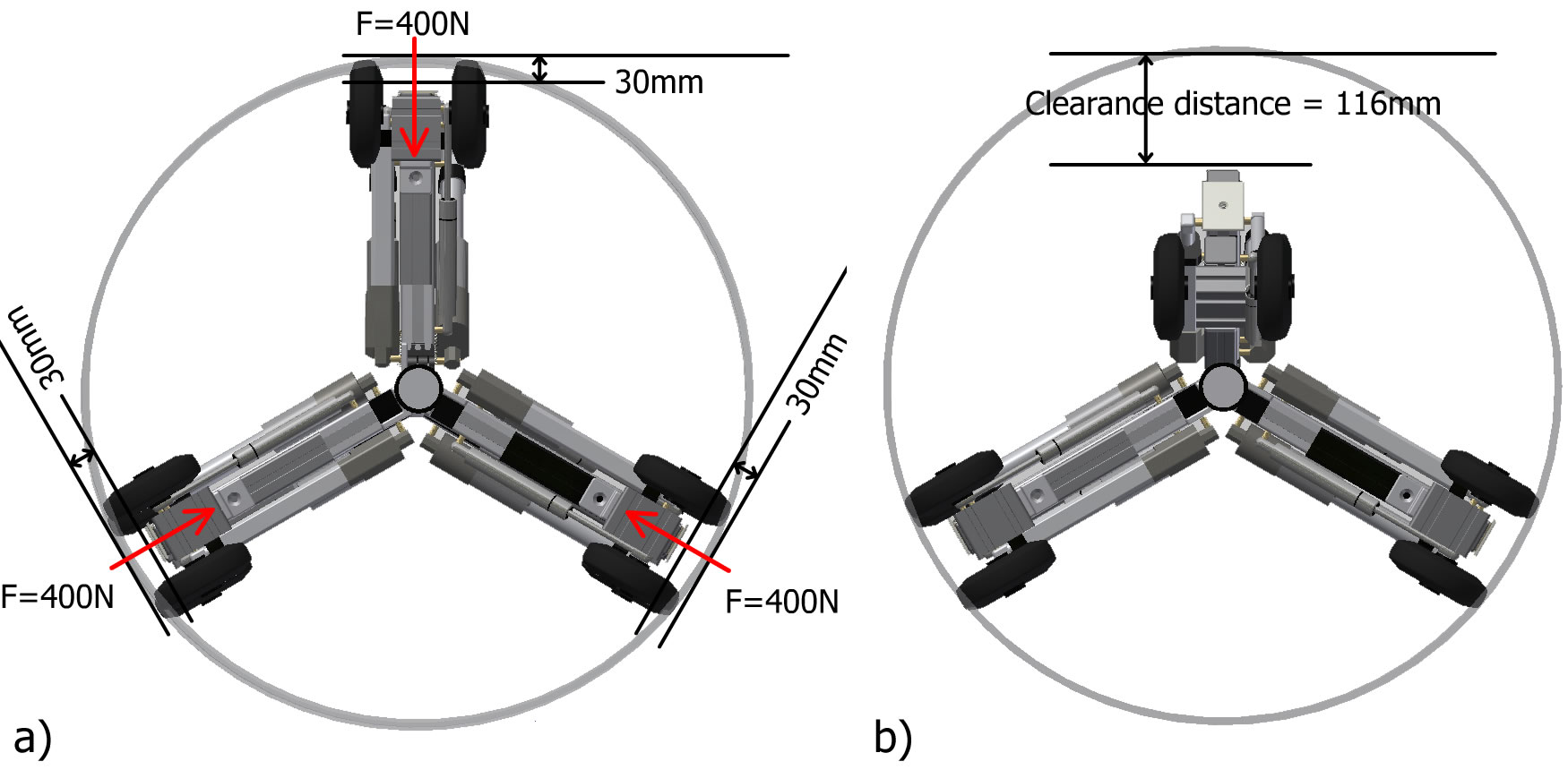
Instead of using brute force to insert the robot into the pipe, an alternative solution is to lower its top wheeled-legs.
In such way, the robot can be easily inserted into the pipe with minimal effort, protecting the legs from hitting the pipe while entering it, as shown in Fig. 7.
And once inside the pipe the robot reconfigure the wheeled-legs as original.
Stiffness to extended wheeled-legs
Another constraint of the in-pipe robot is that once inside the pipe and in locations where its required to rehabilitate the pipe. The wheeled-legs extend creating a centered structure. However, the maximum force the legs can hold is limited to linear actuator specifications.
Hence, if a locking mechanism attaches each wheeled-leg to the maintenance unit structure, then the dynamical structure formed by extending the legs increases its stiffness.
In following sections we will first describe the structure of the robot wheeled-legs, then how we install the two proposed LaMMos mechanism into the legs.
Finally, we will present the procedure of our experiment showing how the LaMMos mechanism helps to reconfigure the robot and make it stronger.
Wheeled-leg before installing LaMMos
A wheeled-leg in DeWaLop robot consists of the following components, see Fig. 9.
1) profile.
2) profile.
3) profile.
4) Linear actuator.
5) Gas spring.
6) Angle bracket .
7) Angle bracket .
8) Angle bracket .
The right-angle brackets are characterized by its high load-bearing capacity to overcome displacement, torsion and deflection. As shown in Table 3, where refers to the operating force that the bracket can hold, and refers to the length of the corresponding part attached by the bracket, see Fig. 8.
| Bracket 8 | |
|---|---|
| Bracket 8 | |
| Bracket 8 |
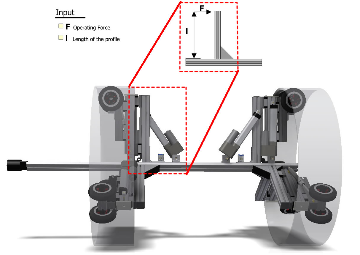
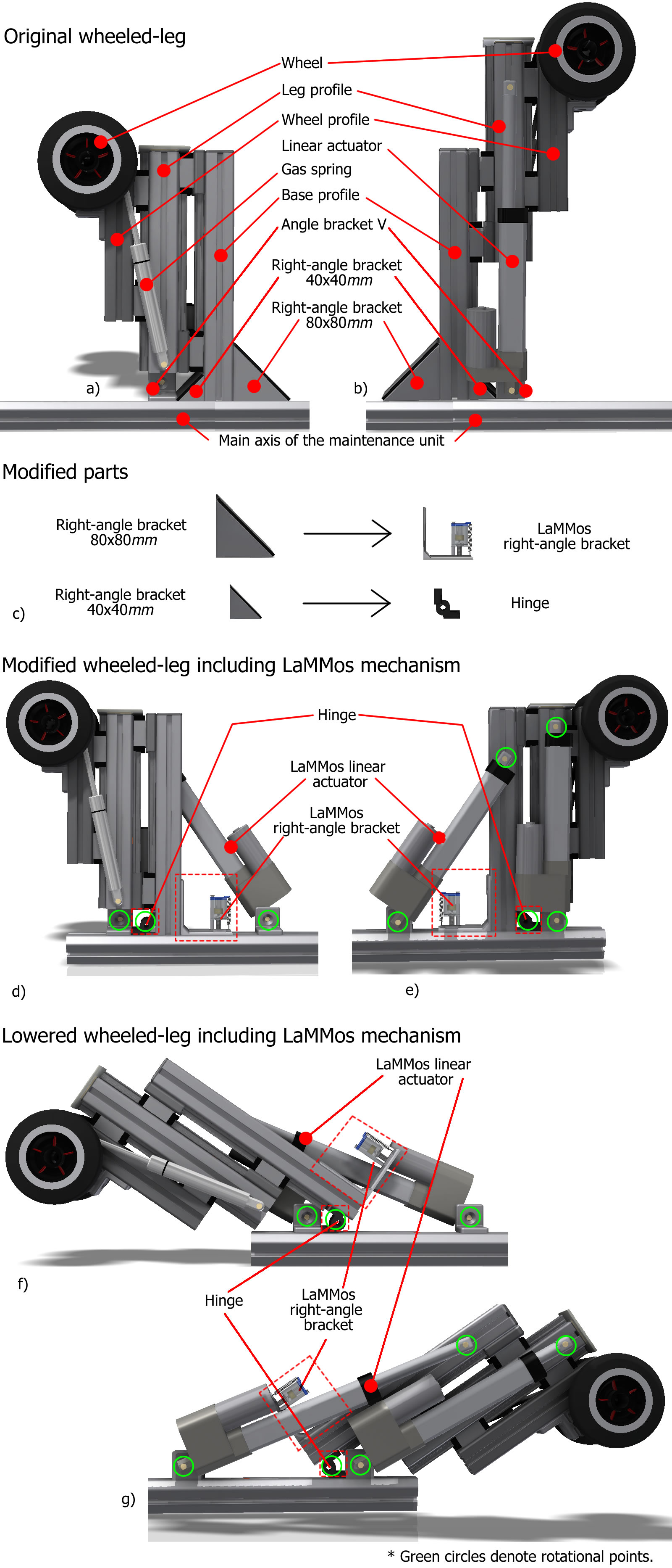
The profile is the main support for the wheeled-leg components as it is attached with a and a right-angle brackets to the maintenance unit axis, as shown in Fig. 9 and 9. To the profile face with the right-angle bracket, linear rails are installed to match the linear bearings from the profile. In this way, the can be extended with a linear actuator, which is attached to the and to the maintenance unit with an angle bracket . In this configuration, the linear actuator extends the leg by pushing and contracts the leg by pulling, as shown in Fig. 9. On the profile, parallel and opposite to the profile, another linear rail with bearings is installed, attaching the profile enabling it to move up or down. Additionally, the profile is supported by an extended gas , connecting the with the , acting as a suspension system, as shown in Fig. 9.
Wheeled-leg after installing LaMMos mechanism for easy robot insertion
The LaMMos mechanism helps DeWaLoP robot to adjust its wheeled-legs to a lower height position before entering the pipe and afterwards helps to recover the original vertical position once the robot is sitting inside the pipe.
The right-angle bracket is replaced by the LaMMos right-angle bracket, while the bracket is substituted by a hinge, as shown in Fig. 9.
In this configuration, the functionality of LaMMos is to attach/detach the right-angle bracket from the profile to the maintenance unit. The functionality of the hinge is to keep the wheeled-leg in contact with the maintenance unit when the LaMMos is detached. In other words, the hinge is required as a joint rotational connection between the profile and the maintenance unit.
Additionally, for lowering the wheeled-leg, a LaMMos linear actuator is required. The linear actuator pushes the leg to be lowered, as shown in Fig. 9 and 9. And by pulling it, sets the wheeled-leg to original position which is perpendicular to the maintenance unit. see Fig. 9 and 9.
In the stage when the leg is vertical, the LaMMos mechanism acts as the replaced right-angle bracket from the profile, as it fastens the wheeled-leg to the maintenance unit using a motorized-screw. It is able to overcome heavy payload due to the rigid structure of LaMMos bracket.
If the leg hit obstacles when performing restoration task, Table 3 shows the maximum forces that brackets with various parameters are able to hold.
We are using bracket for our LaMMos mechanism, so its payload capacity is up to .
Wheeled-leg after installing LaMMos mechanism for high payload capacity
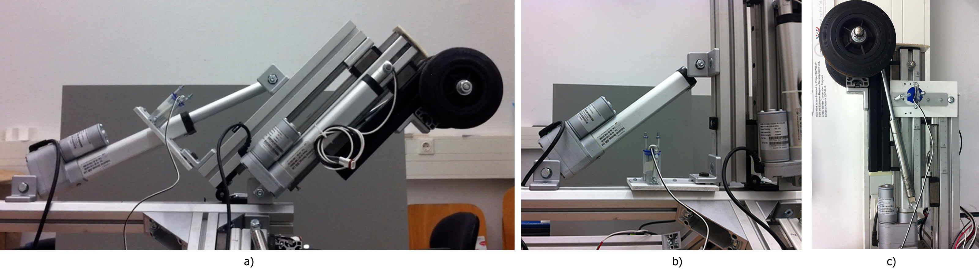
Each wheeled-leg includes a linear actuator for extend or compress the leg in conjunction with a linear slide. In this configuration, when the wheeled-leg is extended, the points of contact from the to the profile are a couple of linear bearings and a linear actuator, as shown in Fig. 9.
The forces acting from the ”foot” of the to the linear actuator cannot be higher than the maximum load capacity of the actuator , otherwise, it will be damaged.
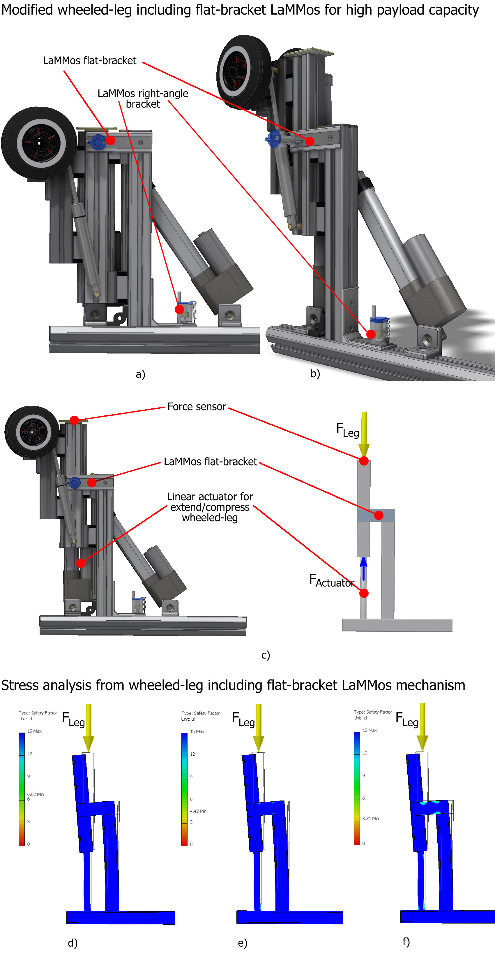
In order to increase dynamically the load capacity of the maintenance unit. The wheeled-legs must be modified to include another LaMMos mechanism as a flat-bracket connecting the to the profile, as shown in Fig. 10.
When the legs are compressed, the LaMMos flat-bracket is unlatched. On the other hand, when the legs are extended and positioning the robot in the center of the pipe, the LaMMos flat-bracket is latched.
The functionality of the LaMMos is to dynamically connect the legs to the structure of the maintenance unit, in order to add stiffness to the structure and protect the linear actuators.
In this way, the forces acting on the profile will be damped by the structure of robot and not directly by the linear actuators.
Safety factor
Consequently, the wheeled-legs are able to hold forces beyond its actuator load capacity by including the LaMMos mechanism.
The included linear actuator in each wheeled-leg is able to hold a maximum load of .
In Fig. 10, the safety factors are obtained from simulated loads of , and acting directly on the extended leg. For this simulation the LaMMos flat-bracket is a steel plate of , and .
The safety factor SF is a term describing the structural capacity of a system beyond the expected loads. Factor of safety guidelines include the following:
A safety factor less than 1.0 at a location indicates that the material at that location has failed.
A safety factor larger than 1.0 at a location indicates that the material at that location is safe.
For many applications, a SF of 4 is a common goal, especially if product durability is an issue.
DeWaLoP robot reconfiguration process
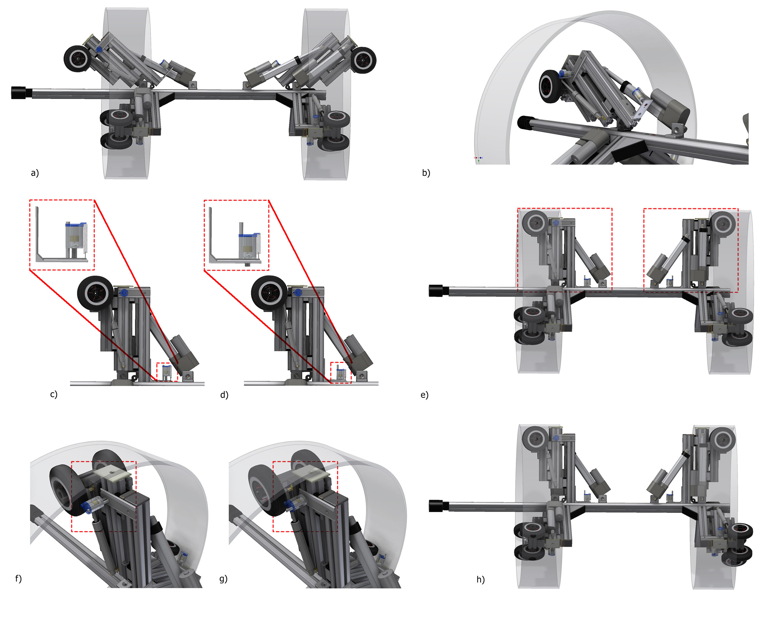
The insertion and reconfiguration process of the DeWaLoP robot inside the pipe is as follows:
Step 1. Initially the LaMMos linear actuator pushes the top wheeled-legs of the DeWaLoP robot, to enter into the pipe with diameter of , as shown in Fig. 11. At this point the wheeled-legs are not rigid, as its only points of contacts to the maintenance unit are the LaMMos linear actuators, the hinges and the linear actuators for extending/compressing the leg.
Step 2. With the operation from the robot remote control, the robot moves into the pipe as it is positioned inside the pipe, see Fig. 11. The linear actuators pull the wheeled-legs until the legs are perpendicular to the maintenance unit axis, see Fig. 11. At this point the LaMMos right-angle brackets are at the right position but is not tight to the T-Slot nut inside the profile.
Step 3. Then, the LaMMos mechanism activates the motorized-screw to rotate clockwise until the screw tights the T-Slot nut inside the maintenance unit, as shown in Fig. 11.
Step 4. The wheeled-legs are re-constructed, the LaMMos right-angle bracket has fasten the profile to the maintenance unit axis. Each of the wheeled-leg is able to overcome forces up to , as shown in Fig. 11.
Step 5. The robot is located inside the pipe and required to rehabilitate a pipe-joint. It extend all its wheeled-legs and once a centered structure has been reached, the LaMMos flat-bracket (integrated on all the wheeled-legs) are activated, connecting the to the profiles of the maintenance unit. In this way, the become part of the maintenance unit structure, as shown in Fig. 11.
Resulting in a rigid structure able to overcome higher forces that its movable actuators, as shown in Fig. 11.
Evaluation of LaMMos mechanism
In the process of attaching the LaMMos bracket to the T-Slot nut inside the maintenance unit, the motorized-screw requires a power supply of delivering a stall torque of , which is enough to tight the bracket securely.
While for unscrewing it, the supplied voltage of the motorized-screw is doubled () with a stall torque of .
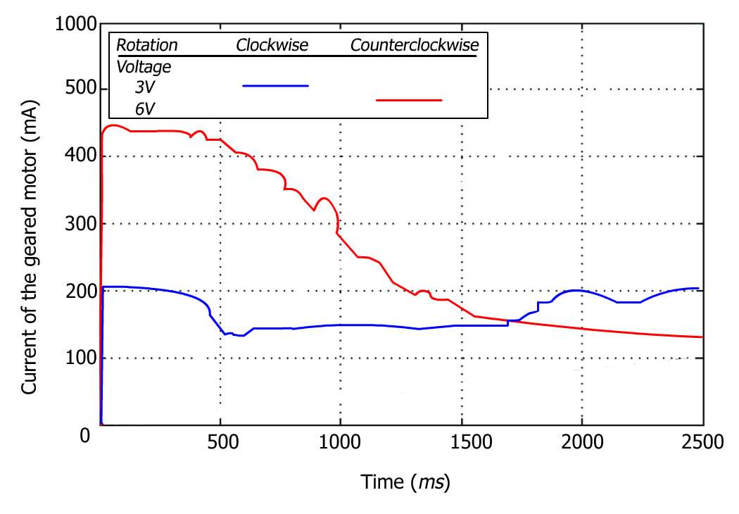
As shown in Fig. 12, initially the LaMMos is housing the screw, then the geared motor starts to rotate clockwise at voltage of . The screw starts to follow the thread from the flexible nut, crossing it and finally reaching the T-Slot nut. To unscrew the motorized-screw, the voltage supply is doubled to . The geared motor reaches a peak current while starting to rotate counterclockwise. Once the screw is out of the T-Slot nut, the current stabilizes while the screw follows the thread of the flexible nut until it is housed inside the LaMMos bracket.
6 LaMMos for Exoskeleton Applications
An exoskeleton is an external structural mechanism with joints and links corresponding to those of the human body 4291584 . There are two main groups of exoskeletons, the ones with unlimited power supply including both wearable types with a tether or those fixed to a base 1639189 5975512 . And the ones that carry their own power supply 4108030 1491470 .
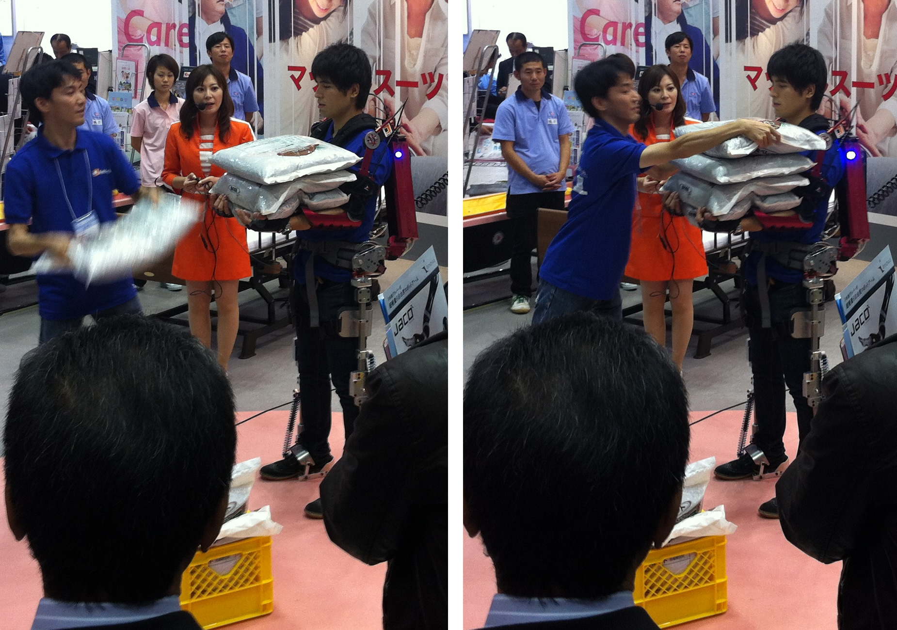
Exoskeletons with unlimited power supply are able to power its actuators and motors for unlimited time. On the other hand, exoskeletons with limited power supply must avoid positions that have high consume of energy in order to save energy and operate longer. Such positions include carrying heavy weights with extended arms, as shown in Fig. 13.
As a result, the available power impose strong limitations on a battery powered exoskeleton 5979863 .
The HAL robot suit
The current HAL (Hybrid Assistive Limb) suit, HAL-5, is a full body exoskeleton that carries its own power supply. It consists of frames interconnected by power units that each contain an electric motor and reduction gears and are positioned directly next to the hip, knee, shoulder (flexion) and elbow joints of the wearer to assist his movements 4108030 .
Additional passive DoF are located at each shoulder, upper arm, and ankle joint. The suit is powered by batteries. The system is controlled according to the intentions of the wearer, which are obtained by measuring the bioelectric signal (BES) on the skin above the main flexor and extensor
muscles associated with each augmented human joint. Motor torques are calculated according to these signals.
Exoskeleton joints
The mechanisms included in exoskeleton joints usually combine slots and rollers mimicking the rolling and sliding of human bones 5979761 .
Also, these exoskeleton joints are limited in strength and in flexibility due to its mechanical configurations and elements 4058569 .
For exoskeletons with limited power supply, servomotors are efficient by including permanent magnets with the capacity of stepping-down gearing to provide high torque and responsive movement in a small package 5975494 6491207 . Geared servomotors can also utilize electronic braking to hold in a steady position while consuming minimal power.
However, even with the most efficient servomotor there will be losses of energy.
LaMMos mechanism in exoskeleton joints
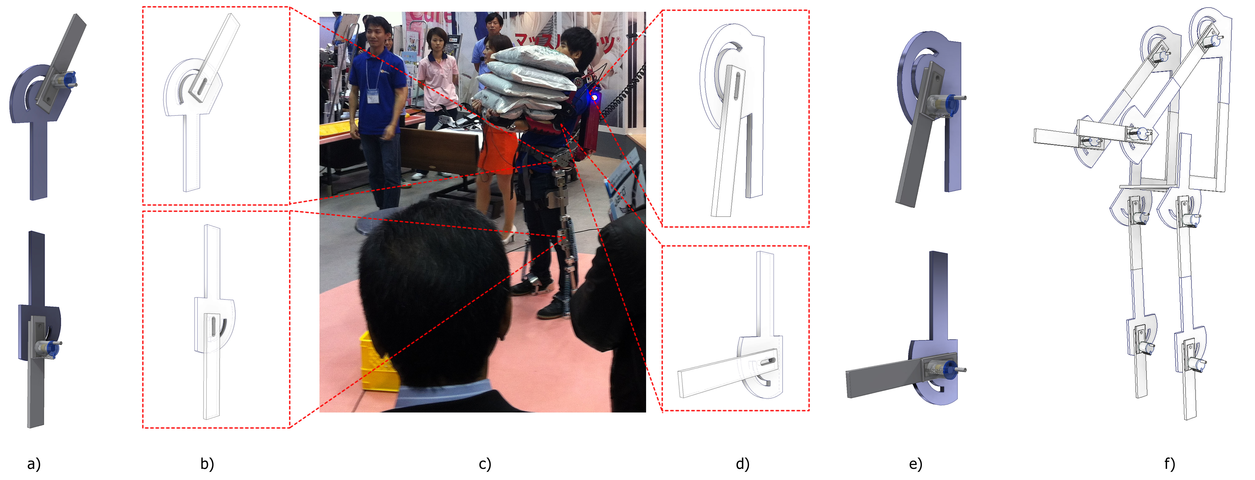
Suppose the classic demonstration of exoskeleton, in which the wearer is required to carry heavy weights with extended arms for a long period of time, see Fig. 14. Or suppose the case of an exoskeleton in the emergency of an earthquake, in which it is holding the roof of a building enabling an exit for people trapped inside.
In these case scenarios, the battery of the exoskeleton will drain fast, due to the demanding power by the motors.
Therefore, we propose to add to the exoskeleton joints the LaMMos mechanism, in order to lock the position of the limbs dynamically when an increase of power consumption is detected or when required by the user. From Fig. 14 and , it is possible to notice that the lower and upper joints mobility are given by the guiding slots. Hence, if the movable plate of the joint integrates a flat-bracket LaMMos for high payload capacity, as shown in Fig. 14 and . Then, the limb can be locked securely in any position and the servomotors from the joints set to standby. And when the task is finished and the exoskeleton is required to move again, the LaMMos are deactivated enabling movement to the exoskeleton as normal.
In this configuration, the joints by including a LaMMos mechanism for high payload capacity are able to dynamically reconfigure the exoskeleton structure to a static rigid structure at any time, see Fig. 14.
7 CONCLUSIONS
This paper introduces a Latching Mechanism based on Motorized-screw (LaMMos) for heavy weight reconfigurable robot. This mechanism improves the payload that other common mechanisms provide.
The LaMMos mechanism requires one motor per each screw, and one actuator per each moving dimension. Hence, the LaMMos mechanism is able to move the robot components in one, two or three dimensional space. And attach the components to the robot body or to other robot parts.
The LaMMos mechanism can be integrated into any type of bracket, we presented the LaMMos as right-angle bracket and as flat-bracket. Moreover, several LaMMos can be included in a single bracket.
The presented LaMMos mechanism is useful when the reconfigurable parts of the robot are required to maintain payloads beyond the limit of its movable actuator. It is able to reconstruct a robot, as if a person with a screwdriver tights the screw on the nut. In this way the robot assemble is optimal as the components are latched with each other as if they are constructed.
For the LaMMos mechanism evaluation, the DeWaLoP in-pipe robot was used and modified, as shown in Fig. 15. Initially a couple of its wheeled-legs were modified to include the right-angle LaMMos bracket instead of rigid brackets. The objective is to lower the wheeled-legs so the in-pipe robot is able to enter its minimal working pipe diameter while protecting it legs. And once inside the pipe reconstruct the robot wheeled-legs as original. The acting forces on the legs of the robot may reach and therefore a latching mechanism with strong stability is required.
ACKNOWLEDGMENT
This work is part-financed by Project DeWaLoP from the European Regional Development Fund, Cross- Border Cooperation Programme Slovakia- Austria 2007-2013.
References
- [1] Ting-li Yang and An-xin Liu and Lu-Zhong Ma and Lu-Bin Hang, Reconfigurable Mechanisms and Robots, 2009. ReMAR 2009. ASME/IFToMM International Conference on, Structure composition principle of reconfigurable mechanisms and basic methods for changing topological structure, 2009, 104 -109
- [2] Andres Castano and Wei-Min Shen and Peter M. Will, CONRO: Towards Deployable Robots with Inter-Robots Metamorphic Capabilities, Auton. Robots, Vol. 8, Num. 3, Year 2000, 309-324
- [3] Yan Meng and Yuyang Zhang and Sampath, A. and Yaochu Jin and Sendhoff, B., Robotics and Automation (ICRA), 2011 IEEE International Conference on, Cross-Ball: A new morphogenetic self-reconfigurable modular robot, May, 267-272, 10.1109/ICRA.2011.5979973, 1050-4729
- [4] Behnam Salemi and Mark Moll and Wei-Min Shen, SUPERBOT: A Deployable, Multi-Functional, and Modular Self-Reconfigurable Robotic System, IROS, 2006, 3636-3641, http://dx..org/10.1109/IROS.2006.281719
- [5] Gilpin, K. and Kotay, K. and Rus, D., Robotics and Automation, 2007 IEEE International Conference on, Miche: Modular Shape Formation by Self-Dissasembly, 2241-2247, 10.1109/ROBOT.2007.363653, 1050-4729
- [6] Wei-Min Shen and Kovac, R. and Rubenstein, M., Robotics and Automation, 2009. ICRA ’09. IEEE International Conference on, SINGO: A single-end-operative and genderless connector for self-reconfiguration, self-assembly and self-healing, 4253-4258, 10.1109/ROBOT.2009.5152408, 1050-4729
- [7] Murata, S. and Yoshida, E. and Kamimura, A. and Kurokawa, H. and Tomita, K. and Kokaji, S., Mechatronics, IEEE/ASME Transactions on, M-TRAN: self-reconfigurable modular robotic system, Vol 7, Num 4, 431-441, 10.1109/TMECH.2002.806220, 1083-4435
- [8] Sproewitz, A. and Asadpour, M. and Bourquin, Y. and Ijspeert, A.J., Robotics and Automation, 2008. ICRA 2008. IEEE International Conference on, An active connection mechanism for modular self-reconfigurable robotic systems based on physical latching, 3508-3513, 10.1109/ROBOT.2008.4543747, 1050-4729
- [9] Behnam Salemi and Mark Moll and Wei-Min Shen, SUPERBOT: A Deployable, Multi-Functional, and Modular Self-Reconfigurable Robotic System, IROS, 2006, 3636-3641, http://dx..org/10.1109/IROS.2006.281719
- [10] Wei Wang and Houxiang Zhang and Jianwei Zhang and Guanghua Zong, Reconfigurable Mechanisms and Robots, 2009. ReMAR 2009. ASME/IFToMM International Conference on, Valid joint workspace and self-aligning docking conditions of a reconfigurable mobile multi-robots system, 2009, 609 -616
- [11] Walsh, C.J. and Pasch, K. and Herr, H., Intelligent Robots and Systems, 2006 IEEE/RSJ International Conference on, An autonomous, underactuated exoskeleton for load-carrying augmentation, 2006, 1410-1415, 10.1109/IROS.2006.281932
- [12] Kyu-Jung Kim and Min-Sung Kang and Youn-Sung Choi and JungSoo Han and Changsoo Han, Rehabilitation Robotics (ICORR), 2011 IEEE International Conference on, Conceptualization of an exoskeleton Continuous Passive Motion(CPM) device using a link structure, 2011, 1-6, 10.1109/ICORR.2011.5975494, 1945-7898
- [13] Smith, R.L. and Lobo-Prat, J. and van der Kooij, H. and Stienen, A.H.A., Rehabilitation Robotics (ICORR), 2013 IEEE International Conference on, Design of a perfect balance system for active upper-extremity exoskeletons, 2013, 1-6, 10.1109/ICORR.2013.6650376, 1945-7898
- [14] Mateos, L. A. and Vincze, M., DeWaLoP Robot Dynamical Independent Suspension System, BookICMET, 287-292, 2011
- [15] Mateos, L. A. and Rodriguez y Dominguez, M. and Vincze, M., Automatic In-pipe Robot Centering from 3D Controller Simplification, BookIROS, 258-265, 2013
- [16] Mateos, L.A. and Vincze, M., DeWaLoP-Monolithic Multi-module In-Pipe Robot System, BookICIRA, 406-415, 2011
- [17] Mateos, L. A. and Vincze, M., DeWaLoP - Robot Vision System, BookCET, 65-68, 2011
- [18] Mateos, L. A. and Rakos, A. and Vincze, M., DeWaLoP In-pipe Redevelopment System Design, BookARW, 101-106, 2012
- [19] Mateos, L. A. and Vincze, M., In-pipe Cleaning Mechanical System for DeWaLoP -Developing Water Loss Prevention, BookARW, 37-42, 2013
- [20] Perry, J.C. and Rosen, J. and Burns, S., Mechatronics, IEEE/ASME Transactions on, Upper-Limb Powered Exoskeleton Design, 2007, Vol 12, Num 4, 408-417, 10.1109/TMECH.2007.901934, 1083-4435
- [21] Nilsson, M., Robotics and Automation, 2002. Proceedings. ICRA ’02. IEEE International Conference on, Heavy-duty connectors for self-reconfiguring robots, 4071-4076 vol.4, 10.1109/ROBOT.2002.1014378
- [22] Mateos, L. A. and Vincze, M., LaMMos - Latching Mechanism based on Motorized-screw for Reconfigurable Robots, ICAR, 2013
- [23] DeWaLoP, Developing Water Loss Prevention EU project, 2013, EU Cross border cooperation program between Vienna and Bratislava , http://www.dewalop.eu
- [24] Magistratsabteilung 31 Wasserwerke, Einfluss des Verkehrs auf die Gebrechens- h uefigkeit von Graugussrohren, Report GZ 541/09 consulting Ziviltechniker GmbH f uer Verkehr, Umwelt und Infrastruktur, Wien, sterreich, 2009
- [25] Perry, J.C. and Rosen, J., Biomedical Robotics and Biomechatronics, 2006. BioRob 2006. The First IEEE/RAS-EMBS International Conference on, Design of a 7 Degree-of-Freedom Upper-Limb Powered Exoskeleton, 2006, 805-810, 10.1109/BIOROB.2006.1639189
- [26] Mateos, L. A. and Zhou, K. and Vincze, M., Towards Efficient Pipe Maintenance: DeWaLoP In-pipe Robot Stability Controller., BookICMA, 1-6, 2012
- [27] Frisoli, A. and Sotgiu, E. and Procopio, C. and Bergamasco, M. and Rossi, B. and Chisari, C., Rehabilitation Robotics (ICORR), 2011 IEEE International Conference on, Design and implementation of a training strategy in chronic stroke with an arm robotic exoskeleton, 2011, 1-8, 10.1109/ICORR.2011.5975512, 1945-7898
- [28] Sankai, Y., SICE-ICASE, 2006. International Joint Conference, Leading Edge of Cybernics: Robot Suit HAL, 2006, P-1-P-2, 10.1109/SICE.2006.314982
- [29] Yoshimitsu, T. and Yamamoto, K., SICE 2004 Annual Conference, Development of a power assist suit for nursing work, 2004, 577-580 vol. 1
- [30] Taal, S.R. and Sankai, Y., Robotics and Automation (ICRA), 2011 IEEE International Conference on, Exoskeletal spine and shoulder girdle for full body exoskeletons with human versatility, 2011, 2217-2222, 10.1109/ICRA.2011.5979863, 1050-4729
- [31] Sankai, Y., SICE-ICASE, 2006. International Joint Conference, Leading Edge of Cybernics: Robot Suit HAL, 2006, P-1-P-2, 10.1109/SICE.2006.314982
- [32] Dong-hai Wang and Jiajie Guo and Kok-Meng Lee and Can-Jun Yang and Hui Yu, Robotics and Automation (ICRA), 2011 IEEE International Conference on, An adaptive knee joint exoskeleton based on biological geometries, 2011, 1386-1391, 10.1109/ICRA.2011.5979761, 1050-4729
- [33] Banchadit, W. and Temram, A. and Sukwan, T. and Owatchaiyapong, P. and Suthakorn, J., Robotics and Biomimetics (ROBIO), 2012 IEEE International Conference on, Design and implementation of a new motorized-mechanical exoskeleton based on CGA Patternized Control, 2012, 1668-1673, 10.1109/ROBIO.2012.6491207
- [34] Mateos, L. A. and Sousa, M. and Vincze, M., book, 2011 15th International Conference on Advanced Robotics (ICAR), DeWaLoP Remote control for in-pipe robot, 2011, 518 -523