A non-oscillatory energy-splitting method for the computation of compressible multi-fluid flows
Abstract
This paper proposes a new non-oscillatory energy-splitting conservative algorithm for computing multi-fluid flows in the Eulerian framework. In comparison with existing multi-fluid algorithms in literatures, it is shown that the mass fraction model with isobaric hypothesis is a plausible choice for designing numerical methods for multi-fluid flows. Then we construct a conservative Godunov-based scheme with the high order accurate extension by using the generalized Riemann problem (GRP) solver, through the detailed analysis of kinetic energy exchange when fluids are mixed under the hypothesis of isobaric equilibrium. Numerical experiments are carried out for the shock-interface interaction and shock-bubble interaction problems, which display the excellent performance of this type of schemes and demonstrate that nonphysical oscillations are suppressed around material interfaces substantially.
I Introduction
It is noticed that in the computation of compressible multi-fluid flows, there are usual difficulties due to nonphysical oscillations generated at material interfaces when conservative schemes are used. This phenomenon can be unfolded by a simple example on a Cartesian structural mesh using a standard shock-capturing method. A moving material interface is initially aligned on the right boundaries of a row of cells, and separates the computational domain into two parts with different fluid materials, but with uniform pressure and non-zero velocity. Due to different thermal equations of state (EOS) for the two fluids, numerical errors of pressure and velocity may be produced and propagate away from the material interface between the forward and backward characteristic waves. Fixing the present Cartesian coordinates and fluid data, and rotating the structural mesh, it is found that this oscillatory phenomenon never disappears. In addition, if there is a shock wave interacting with the interface, density oscillations may be enlarged. Due to the possible presence of shocks in compressible multi-fluid flows, conservative schemes are appealing in the practical applications.
A slew of results on this subject were listed in Abgrall and Karni’s review articleAbgrall and Karni (2001). There were two typical frameworks for numerically simulating multi-fluid dynamics: the front-tracking method and front-capturing method. The front-tracking method takes discontinuities (including material interfaces) as moving fronts, which preserve the sharpness of interfaces. The solution of the associated Riemann problem across fronts gives an indication of the motion of the frontsChern et al. (1986); Grove and Menikoff (1990); LeVeque and Shyue (1996). The front tracking method eliminates the numerical diffusion and reduces post-shock oscillations common to shock-capturing methodsHolmes, Grove, and Sharp (1995). An example is that Cocchi and Saurel proposed a front-tracking method consisting of a predictor step and a corrector step in order to prevent spurious oscillations near interfacesCocchi and Saurel (1997).
The front-capturing method (shock-capturing method in this paper) simulates multi-fluids using the integral (finite volume) form of the governing equations. In order to identify each fluid, we need to couple the Euler equations with the (ratio of specific heats)-modelAbgrall (1994); Karni (1994); Shyue (1998), the volume fraction modelShyue (1998), the mass fraction modelBanks et al. (2007); Larrouturou (1991); Quirk and Karni (1996) or the level-set modelKarni (1994, 1996); Mulder, Osher, and Sethian (1992). For these models, some single-fluid algorithms and quasi-conservative or non-conservative approaches were suggested to ensure the correct numerical fluid mixing rules at interfaces. For example, a non-conservative -model, using small viscous correction terms to remove leading-order conservation errors, was presented in terms of primitive variablesKarni (1994). Then some quasi-conservative approaches was designed for the energy equation and the -modelAbgrall (1994); Shyue (1998), in order to deal with strong shocks and prevent pressure oscillations through the interfaces. For the volume or mass fraction models, it is natural to ask how these models are closed or how to compute through the mass fractions or the volume fractions. In Ref. Allaire, Clerc, and Kokh, 2002, two different closure laws were proposed with detailed mathematical analysis of the properties of the resulting models: isobaric and isothermal closures. Applying the isobaric and isothermal closures, Banks et al. introduced a high-resolution Godunov-type method with a total energy correction which is based on a uniform-pressure-velocity (UPV) flow. Another simple correction of the internal energy inside computational cells was proposed in Ref. Jenny, Müller, and Thomann, 1997 to avoid spurious pressure oscillations near material interfaces. These two methods based on energy corrections do not conserve the total energy generally, unless fluids are in thermal equilibrium. The level-set method was extensively adopted in the simulation of multi-fluid flows, using the sign of a function to identify different fluids. This method, combined with some nonconservative techniques to reduce non-physical pressure oscillations around interfacesKarni (1996, 1994). The ghost fluid method (GFM)Fedkiw et al. (1999) was a representative of the modified level set method with excellent numerical performance and an adaptive mesh refinement extension of GFM can be found in Ref. Nourgaliev, Dinh, and Theofanous, 2006. GFM can also be used to define interface conditions in the front-tracking methodTerashima and Tryggvason (2009).
There are many other multi-fluid approaches available in literature, such as the volume-of-fluid (VOF) method Colella, Glaz, and E. Ferguson (1989); Miller and Puckett (1996); Ton (1996), the moment-of-fluid (MOF) methodDyadechko and Shashkov (2005) and the BGK-based modelXu (1997). The VOF method solves the evolution equations for volume fractions, the mass and energy equations for individual fluids, and the momentum equation for the fluid mixture, and it was improved in Ref. Ton, 1996 to eliminate pressure oscillations by defining mixtures inside each cell with different temperatures and solving an extra one-phase energy equation. Ton’s approach relieved the need to solve the evolution equations for volume fractions. The MOF method, another numerical approach, was proposedAhn, Shashkov, and Christon (2009) by using the volume fraction and centroid for a more accurate representation of the material configuration, interfaces and volume advection.
Lagrangian and ALE frameworks are preferable in the compressible multi-fluid flows due to their sharp capturing ability of material interfaces. There are a lot of contributions on Lagrangian and ALE schemes, see Refs. Kamm and Shashkov, 2009; Hirt, Amsden, and Cook, 1974; Galera, Maire, and Breil, 2010 and references therein. Still, an indispensable ingredient has to be added in order to avoid the occurrence of pressure oscillations at material interfaces, such as a pressure relaxation technique in the Lagrangian Godunov method with Tipton’s closure modelKamm and Shashkov (2009). A comparative study of multi-fluid Lagrangian and Eulerian methods was made in Ref. Francois et al., 2013, and a relaxation-projection method by Lagrangian plus remapping the flow quantities to the Eulerian mesh was designed in Ref. Saurel et al., 2007.
It is worth noting that any non-conservative scheme may converge to wrong solutionsHou and LeFloch (1994), providing incorrect internal energy or shock wave positions. Hence, researchers hope to simulate compressible multi-fluid flows using conservative schemes in the Eulerian framework. For this purpose, we propose an algorithm in this paper, based on the Godunov method, that can prevent non-physical oscillations at interfaces without sacrificing the numerical results of the compressible flow phenomena involving shock waves and rarefaction waves. Inspired by Ref. Ton, 1996, we solve an equation of mass fraction and a one-phase energy equation coupling with the Euler equations. In order to simulate kinetic energy more accurately, we add a one-phase momentum equation for correction. As far as the interaction of shocks and interfaces is concerned, the exchange of kinetic energy is processed. Motivated by Ref. Jenny, Müller, and Thomann, 1997, we use the isobaric equilibrium condition to compute the volume fractions and the ratios of specific heats inside mixed fluid cells. A benefit of this method is its conservative form, which allows to suit for the finite volume framework. The resulting scheme is of Godunov-type, and an second order accurate extension is made by using the space-time coupled generalized Riemann problem (GRP) solver Ben-Artzi, Li, and Warnecke (2006); Ben-Artzi and Falcovitz (2003). The reason of making a choice is the inclusion of thermodynamics into the schemeLi and Wang (2017). It is theoretically shown that the non-oscillatory property in pressure can be preserved across material interfaces. Although this paper takes two-fluid flows to illustrate the method, the proposed algorithms can be applied to multi-fluid flow models even when computed over unstructured meshes.
To demonstrate the performance of the proposed schemes, we carry out several numerical experiments typically for illustrating the simulation of compressible fluid flows. They are a two-fluid compression problem in order to show the necessity of kinetic energy exchange during fluid mixture; the shock-interface interaction, and the shock-bubble interaction problems.
We organize this paper as follows. In Section II, we describe basic models for immiscible compressible multi-fluid flows and discuss the cause of pressure errors. We provide the motivation of our non-oscillatory scheme in Section III, and propose the numerical method in Section IV. To display the performance of the current method, we provide several typical numerical results in the context of multi-fluid flows including the interaction of shock-interface and the interaction of shock-bubble in Section V.
II Physical models for two-fluid flows
Under the assumption that all fluid variables are described by a single density , a single pressure and a common fluid velocity , the Euler equations representing conservation of mass, momentum and energy for inviscid compressible multi-fluid flows take the form
| (1) |
| (2) |
| (3) |
where is the specific internal energy specified by an EOS for the mixture. For two immiscible fluids and , we denote as their volume fraction, mass fraction, density, pressure, specific internal energy, temperature, specific heat capacity at constant volume and ratio of specific heats, respectively with . Principles of volume average tell us of the mixture rule of thermodynamical parameters
| (4) |
In light of the fact
| (5) |
the mixture rule is written as
| (6) |
In this paper, we assume that fluids are modeled by the EOS for ideal gases
| (7) |
Under Dalton’s law of partial pressures
| (8) |
the mixture EOS has the unified form
| (9) |
where is the effective ratio of specific heats for the mixture given by
| (10) |
So far, various methods computing had been proposed in literatures, e.g. Refs. Abgrall and Karni, 2001; Ton, 1996, depending on different model assumptions. In the following, we sketch two typical cases.
II.1 Mass fraction model with isothermal hypothesis
For the ideal gas , is assumed to depend only on temperature, and the thermal EOS is
| (11) |
Following Refs. Jenny, Müller, and Thomann, 1997; Banks et al., 2007; Larrouturou, 1991; Quirk and Karni, 1996, an isothermal hypothesis is used to express in Eq. (10) explicitly by
| (12) |
The equation of mass conservation for fluid is
| (13) |
Therefore, is representable for the mixture through the solution of this one-phase mass conservation equation. This, together with the Euler equations (1)-(3), gives a four-equation model in conservation form. It is typical to use a conservative shock-capturing scheme, such as the Godunov scheme, to numerically solve this model. Let us simulate a material interface separating two fluids with different temperatures and ratios of specific heats. In the Eulerian framework, a moving material interface enters the interior of some computational cells.

As shown in FIG. 1, there is a cell filled with two separate fluids and with the same velocity, satisfying the initial conditions and . For the time being, we assume all that fluid variables on both sides of the material interface in the cell are constants. Resulting from the isothermal equilibrium, internal energy must exchange between these two fluids. It turns out that pressure changes to with fixed mass fraction and total internal energy . The isothermal equilibrium is expressed as
Conservation of total internal energy before and after isothermal equilibrium shows that
Then are known. In the end, the pressure in the cell after isothermal equilibrium described by Dalton’s law
is not equal to . It turns out that a dramatic change of the pressure arises from the material interface of the fluid mixture. To prevent the pressure error, some shock-capturing schemes using energy corrections was designed for a UPV flowBanks et al. (2007) or the convection of the internal energyJenny, Müller, and Thomann (1997). These schemes can reduce the pressure error efficiently, but their total energy looses conservativity. Sometimes, this non-conservation destroys the simulation of internal energy distribution (see the example in Sec. V.3) or obtains more inaccurate shock position (example in Sec. V.2). Hence, we had better build an appropriate conservative model evading the isothermal equilibrium, i.e., internal energy exchange between two fluids, in the computational cells.
II.2 Volume fraction model with isobaric hypothesis
To maintain pressure equilibrium across material interfaces, as shown in Refs. Allaire, Clerc, and Kokh, 2002; Shyue, 1998, an isobaric hypothesis is made to express in Eq. (10) explicitly by
| (14) |
Since the volume fraction propagates with the fluid velocity , the transport equation for is written as
| (15) |
The use of this transport equation results in non-conservative schemes, which, though, can effectively prevent the pressure oscillations around the interfaces. For the computation of compressible multi-fluid flows, the underlying scheme is often required to be conservative to capture shocks correctly (an example can be found in Sec. 4.1 of Ref. Abgrall, 1994, and in Sec. V.2 of the present study), for which Godunov-based schemes are a natural choice. Therefore, we have to face on the challenge due to the conflict between the non-conservativity for capturing interfaces and the conservativity for capturing shocks.
III An energy-splitting method without internal energy exchange
In view of the analysis in the previous section, it is a plausible way to make isobaric hypothesis in order to design a non-oscillatory conservative scheme for multi-fluid flows. In the following, we will explain the motivation and rationality of an energy-splitting method without internal energy exchange between materials, based on the four-equation model and Dalton’s law of partial pressures.
III.1 Hypothesis: no internal energy exchange between materials
At first, we use the mass fraction model with isobaric hypothesis. In this case, we can compute the mass fraction through Eq. (13). Note that this equation does not provide the volume fraction directly so that we need to close the thermodynamic system for computing the volume fraction based on the isobaric hypothesis and other reasonable physical hypothesis. Recalling Sec. II.1, we have proved that there is pressure error across material interfaces due to isothermal hypothesis, which means the temperature of two materials reaching temperature equilibrium in a cell. In the process of temperature equilibrium, the exchange of the temperature between two materials in a cell causes the pressure error. Hence, it is reasonable to avoid changes of the temperature inside cells containing material interfaces, which means the temperature of two materials inside cells remain unchanged. It implies that there is no exchange of internal energy between materials.

As shown in FIG. 2, there is a cell full of two separate fluids and moving with a common velocity , but with different initial pressures . Using the Godunov averaging (first order), all fluid variables are considered as constants in the cell. The initial volume fraction of fluid is . As physical quantities are in equilibrium in the cell, the velocity, pressure and the volume fraction become and , respectively. We assume that there is no exchange of internal energy between two materials in the equilibrium process. Thus after the isobaric equilibrium, density and specific internal energy for fluid in a cell remain unchanged. As the internal energy and remain unchanged
we note that Dalton’s law still holds
and find
which means that the material interface moves inside the cell. This procedure can be found in Ref. Jenny, Müller, and Thomann, 1997. Thus in the Eulerian framework, the equation (15) is imperfect in the case of non-equilibrium pressure between the two fluids. However, for this case, we can compute the effective ratio of specific heats for the mixture in Eq. (10) through the internal energy for individual fluid
| (16) |
as long as we know the specific internal energy . Then, an important question is how to compute . In this subsection, we only consider the two separate fluids and moving with a common velocity. So what happens to fluids at different velocities? And do the different velocities of fluids and affect the computation of ? We will discuss these in the next subsection.
III.2 Computation of the kinetic energy exchange in a cell
Since there is only one common velocity in the present model, a process of velocity uniformity in the cell arises when two separate fluids with different velocities enter a same cell. As far as the interaction of shock wave and material interface is studied, this situation must happen. After the process of velocity uniformity, the momentum of the two fluids has been exchanged, which causes the exchange of kinetic energy between fluids. However, the total momentum and total energy of two fluids remain unchanged throughout the process. Similarly as shown in FIG. 1, we assume that there is a cell filled with two separate fluids and moving with different velocities . However in practical computation, we consider the two fluids moving with a uniform velocity . This process of uniformizing different velocities in a cell means the velocities of fluids and both become . In this process, the total momentum remains unchanged
| (17) |
The kinetic energy of is increased by
and the kinetic energy of is decreased by
where the subscript ‘K’ represents ”Kinetic”. The changes of kinetic energy for fluids and indicate the exchange of kinetic energy between fluids. Then under a rough hypothesis that energy exchange meets the principle of mass fraction distribution, the energy of fluid is increased from the energy of in amount of
| (18) |
Using this kinetic energy exchange, we can simulate the values of total energy for two separate fluids at each step of velocity uniformity. After the kinetic energy exchange, the total energy of fluid before equilibrium
becomes
| (19) |
Similarly, as the total energy of two fluids remains unchanged, the initial total energy of fluid becomes
| (20) |
According to the above formulae, we obtain the internal energy .
This process of kinetic energy exchange is independent of the previous pressure equilibrium process. Without the manipulation of kinetic energy, the model can be only operated normally in the flow field with small pressure and velocity gradients across material interfaces. For other methods, only the convection of internal energy is considered, e.g. in Ref. Ton, 1996, without the exchange of kinetic energy. However, in the case of large velocity gradient, such as the numerical simulation of detonation process, the manipulation of kinetic energy is necessary. See Sec. V.1 for the numerical evidence.
III.3 Computation of the volume fraction for fluid
In the following, we give the partial differential equations to compute the momentum and total energy of fluid . We consider that the pressure reaches equilibrium and the velocity reaches uniform in a flash on the entire computational region. For a fluid parcel containing two fluids, in light of Dalton’s law with equilibrium pressure , the partial pressure of fluid is , where is the volume fraction of fluid in the fluid parcel. In the numerical computation, we take each computational cell as a fluid parcel. Motivated by a single-pressure compressible stratified flow model introduced in Ref. Chang and Liou, 2007, we assume that the partial pressures of fluids also obey Dalton’s law and reach equilibrium at cell interfaces. Then, with the equilibrium pressure at cell interfaces, the partial pressure determines the pressure terms of fluxes in the momentum equation and energy equation for fluid . And we assume the velocities for two fluids are uniform in the fluxes at cell interfaces. Then the momentum equation of fluid is
| (21) |
and the momentum equation of fluid is
| (22) |
where is the velocity of fluid . In these two momentum equations, the convection term in the flux depends on the mass fraction, yet the pressure term in the flux depends on the volume fraction, which are physically reasonable. The addition of these two momentum equations is Eq. (2). According to these two momentum equations, we can obtain the velocities and after each computational time step, and may not be equal to . Therefore, after each computational time step, we have a process of uniformizing different velocities in Sec. III.2, i.e. the kinetic energy of fluid increased from the kinetic energy of in amount of
| (23) |
After that, the velocities and reach a uniform velocity , which is the initial velocity of and at the next computational step.
In addition, the energy equation of fluid in conservative form is
| (24) |
where represents pressure work. Thus the energy equation (3) can be split into two parts: Eq. (24) and
| (25) |
According to the energy equation of fluid , we can obtain the total energy of fluid , , after each time step. Thanks to the process of velocity uniformization, the total energy of fluid is increased by in Eq. (23) at each step. This is the process of the kinetic energy exchange at material interfaces described in Eq. (19). Furthermore, according to hypothesis that do not exchange with each other as described in Sec. III.1, the pressure equilibrium process does not cause any change in specific internal energy . Then we can use the total energy of fluids available in Eq. (19) to compute after pressure equilibrium. Based on the isobaric hypothesis, we are able to obtain the volume fraction by Eq. (5) and
which imply
| (26) |
This is the initial volume fraction of fluid in cells at the next computational step. Another form of total energy equation for fluid in non-conservative form was proposed in Ref. Miller and Puckett, 1996, and modified in Ref. Ton, 1996 to compute partial pressures and ratios of specific heats. However, since the equation is in non-conservative form in those studies, it is difficult to define numerical integral paths for constructing a conservative finite volume scheme converging to correct weak solutionAbgrall and Karni (2010), especially over unstructured meshes.
IV A Non-Oscillatory Conservative Scheme for Capturing Material Interfaces
In order to maintain pressure equilibrium and mass conservation of each material across the material interface, we use the mass fraction model with isobaric hypothesis. Therefore, for any infinitesimal fluid parcel in which the flow field is continuously differentiable, the governing equations for the fluid mixture and the fluid take the conservative form
| (27) |
with
where is the volume fraction of fluid in the fluid parcel (computational cell), and is the velocity of fluid . A system of equations, similar to (27), can be derived for fluid , but both of them are equivalent.
The conservative form of (27) allows us to use the finite volume framework to design numerical schemes, particularly in multi-dimensions.
IV.1 A full-discrete finite volume method
We discretize the governing equations (27) with a cell-centered finite-volume scheme over a two-dimensional computational domain divided into a set of polygonal cells . The integral average of the solution vector , , over cell at time is given by . Taking rectangular cells as an example, we denote as the integral average over the -th adjacent cell of , as in FIG. 3.

The Godunov scheme assumes that the fluid data at time are piece-wise constant distribution. Then taking the cell as a fluid parcel, we know that the volume fraction in the cell is . By solving the exact Riemann problem , we can obtain the solution at the -th boundary between and . Then the finite-volume scheme with the Godunov fluxes is given by
| (28) |
where , is the length of the -th boundary of the cell , is the volume of , is the unit vector outward normal to the -th boundary, and . Specifically, the exact Riemann problem is solved for the planar one-dimensional Euler equations in the normal direction of the boundary between and ,
| (29) |
The effective ratio of specific heats in is computed by using Eq. (12)
| (30) |
Detailed process of the computation for the Godunov fluxes can be found in Refs. Ben-Artzi and Falcovitz, 2003 or Toro, 1997. Using the solution at the -th boundary, the mass fraction and volume fraction in the fluxes are determined as
| (31) |
and
| (32) |
It can be proved that this condition preserves the positivity of the mass fractionsLarrouturou (1991). Then, we have the solution and the fluxes at the -th boundary. Especially, the last component of is
IV.2 Computation of internal energy for fluid
We use the energy equation of fluid in Eqs. (28) to update the total energy of fluid , . According to the momentum equations of fluid in Eqs. (28), we are able to compute the momentum for fluid , , before the velocity uniformity at next time . If the two immiscible fluids and have different velocities, their velocities achieve uniformity
In the process of velocity uniformization, the exchange of kinetic energy from fluid to fluid can be estimated as
Then we obtain the internal energy for fluid at time , , through the total energy of fluid after the velocity uniformity
| (33) |
The velocity of fluid becomes . The exchange process of kinetic energy is necessary for extreme situations with large velocity gradient. For more extreme situations, due to the admissible error of simulating kinetic energy exchange, the internal energy of or , or may be less than 0. A computational process is to truncate it to be zero, which means the internal energy is extremely small. This situation basically does not appear with the exchange process of kinetic energy (see Sec. V.1). In this way, we can guarantee the positivity of volume fractions, since now the volume fraction in is
| (34) |
To sum up, we get a non-oscillatory Godunov scheme for two-dimensional multi-fluid flows. Such a scheme is termed as the energy-splitting Godunov scheme (ES-Godunov for short).
IV.3 Second-order accurate extension
We make a second-order accurate extension of ES-Goduov by using the generalized Riemann problem (GRP) solver Ben-Artzi, Li, and Warnecke (2006); Ben-Artzi and Falcovitz (2003) (ES-GRP for short). The two-dimensional finite-volume GRP scheme for Eqs. (27), is written as
| (35) |
where the mid-point value is derived analytically by resolving the GRP at the -th boundary with accuracy of second order. In each cell, we project conservative variables in the form
| (36) |
where is the gradient of solution inside the cell at time , and is the centroid of . We indicate a parameter and the minmod function(van Leer, 1979; Ben-Artzi, Li, and Warnecke, 2006)
| (37) |
For the rectangular cells, the gradient
| (38) |
is calculated as
and
where
and
| (39) |
We solve the generalized Riemann problem at the -th boundary for the planar one-dimensional Euler equations in (29) at the center to define the Riemann solution and determine the temporal derivative . The temporal variation of the fraction is calculated as
| (40) |
by adopting the equation (15), where is the gradient of inside the cell calculated by the same process as for . Thus we have the mid-point value inside cells
| (41) |
and the mid-point values on cell interfaces
| (42) |
| (43) |
which further gives by
| (44) |
Thus the last component of in (35) becomes
Using the same approach as in ES-Godunov to compute the internal energy for fluid , we obtain a second-order non-oscillatory scheme for two-dimensional multi-fluid flows. This method has the non-oscillatory property.
Remark. For high-order Godunov-type methods, the energy modification can be made to the averaged flow quantities, in the same way as the corresponding first order schemes. Then we implement the linear reconstruction process to obtain the linear distribution as in (36).
Indeed, we consider the solution of the GRP scheme at an interface with uniform velocity and pressure . Using the fact
| (45) |
and full-discrete scheme (35), we have
and
In view of Eq. (34), we have
| (46) |
and then
| (47) |
due to the pressure equilibrium. Then we proceed to obtain
and
Finally, we can get the pressure at time
This shows that no pressure oscillation appears at the material interface.
Finally, we would like to remark that the GRP solver has the feature that the thermodynamics is deeply characterized and embedded into the schemeLi and Wang (2017).
V Numerical Results
We present some numerical results by using the current energy-splitting Godunov-type methods in Section IV . The results are compared with those computed by the Godunov-type methods in Ref. Banks et al., 2007. We abbreviate Is-Godunov for the results by using the Godunov method with the isothermal hypothesisLarrouturou (1991); Quirk and Karni (1996), UPV-Godunov for the Godunov results with the energy correction based on a UPV flowBanks et al. (2007), in addition to the abbreviations: ES-Godunov and ES-GRP. The process of the kinetic energy exchange is added into ES-Godunov and ES-GRP for the simulation. The following examples show that nonphysical oscillations arising from the interface are avoided by using the current non-oscillatory conservative schemes. Through the comparison with the corresponding physical experimental results, the numerical results show that the current schemes perform well for two-dimensional cases with very sharp interfaces. For all examples, the CFL number is taken to be 0.45.
V.1 Demonstration for the kinetic energy exchange
| Scheme | Step 1 | Step 2 | Step 3 | Step 4 | Step 5 |
|---|---|---|---|---|---|
| ES-Godunov(NO-KE) | |||||
| ES-GRP(NO-KE) | |||||
| ES-Godunov | |||||
| ES-GRP |
The exchange of kinetic energy in the process of fluid mixture has not been well studied in literatures. Hence we propose an example to show the influence of the kinetic energy exchange on the distribution of fluids inside mixed cells. We consider an inward two-fluid compression problem, for which the initial discontinuity at separates fluid with in the left from fluid with in the right. These two fluids can be regarded as air in the left and wolfram in the right. The initial data in the entire computational domain , composed of cells, are given as
The left boundary is a solid wall and the right boundary has an inflow condition. This problem has exceedingly huge density ratio and velocity gradient. We use NO-KE to represent no kinetic energy exchange in the scheme, and list the numerical results of in the -th cell at time steps to in Table 1. It is observed that without the process of kinetic energy exchange, the volume fraction of air at the interface becomes negative value, which immediately ruins the numerical simulation. This shows the necessity of the numerical correction of the kinetic energy exchange into the current method.
V.2 Two-fluid shock-tube problem
We consider a two-fluid shock-tube problem in Ref. Abgrall, 1994. The discontinuity initially at separates air with in the left from helium with in the right. Then the initial data in the entire computational domain , composed of cells, are given by
The exact solution of the shock-tube problem consists of a left-propagating rarefaction wave, a contact discontinuity moving at the speed of , and a right-propagating shock wave at the speed of . We compare the solutions computed by different schemes at time .

(a)density

(b)pressure

(c)velocity

(d)mass fraction of fluid
All numerical solutions with the mass fraction model are shown in FIG 4. The gray curves are the exact solution; the red marks “v” are the solution by Is-Godunov; the orange circles are the solution by UVP-Godunov; the blue marks “x” are the solution by the current method ES-Godunov, and the black plus signs represent the solution by ES-GRP with . The numerical errors of pressure and velocity occur in the Is-Godunov solution. The results by the current ES-Godunov and ES-GRP are much closer to the exact solution without oscillations than that by UPV-Godunov. This shows the performance of the current schemes.
V.3 Shock-interface interaction
We consider a shock-interface interaction problem. The interface initially at separates fluid with in the left from fluid with in the right. These two materials, used in Ref. Banks et al., 2007, correspond to high explosive products in the left and a confining material in the right. The interface and a shock wave with the shock Mach number initially at propagate to the right at the speed of and , respectively. Then the initial data in the computational domain , composed of cells, are given by
At time , the interface is impacted by the shock wave. The resulting wave pattern after the interaction consists of a reflected rarefaction wave, an interface at the speed of , and a transmitted shock at the speed of . We compare the profiles of pressure and internal energy by using different methods at in FIG. 5. The parameter of the GRP method is for this example.
(a)pressure

(b)specific internal energy
Each mark represents the same solution as in the previous example. Serious pressure oscillations are generated from the interface and induced error of the internal energy occur in Is-Godunov or UVP-Godunov solutions. Although UVP-Godunov scheme can prevent the pressure oscillations, incorrect internal energy shows the defect of such a scheme. Therefore it is reasonable to believe that other methods with energy correction, such as that in Ref. Jenny, Müller, and Thomann, 1997, may obtain incorrect numerical results of internal energy. In contrast, the current method can produce much better results.
V.4 Shock-bubble interactions
The fourth example is about the interaction problem of a planar shock wave with a cylindrical gas bubble. This problem is motivated by the experiments in Ref. Haas and Sturtevant, 1987, and some existing numerical simulations can be found in Refs. Quirk and Karni, 1996; Allaire, Clerc, and Kokh, 2002; Banks et al., 2007; Ton, 1996; Fedkiw et al., 1999. In the experiments, a weak shock with the shock Mach number propagates from atmospheric air into a stationary cylindrical bubble filled with lighter helium or heavier Refrigerant 22(R22). The computational domain composes of square cells and the position of initial discontinuity is set in FIG. 6.

The upper and lower boundaries are solid wall boundaries, whereas the left and right boundaries are non-reflective. The air outside and the gas inside the bubble are assumed initially to be in the temperature and pressure equilibrium, and the density and pressure of air outside the bubble are set to be unit.
| Gas | Air | Helium+28%Air | R22 |
|---|---|---|---|
For the helium bubble case, the gas in the bubble is assumed as a helium-air mixture where the mass fraction of air is , which is explained in Ref. Haas and Sturtevant, 1987. These materials are regarded as ideal gases, for which and are taken from Ref. Quirk and Karni, 1996 and presented in Table 2. Then the density of the gas inside the bubble is
(a)
(b)
(c)
(d)
(e)
(f)


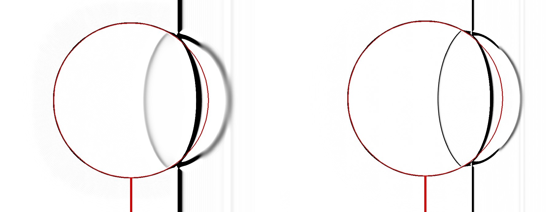
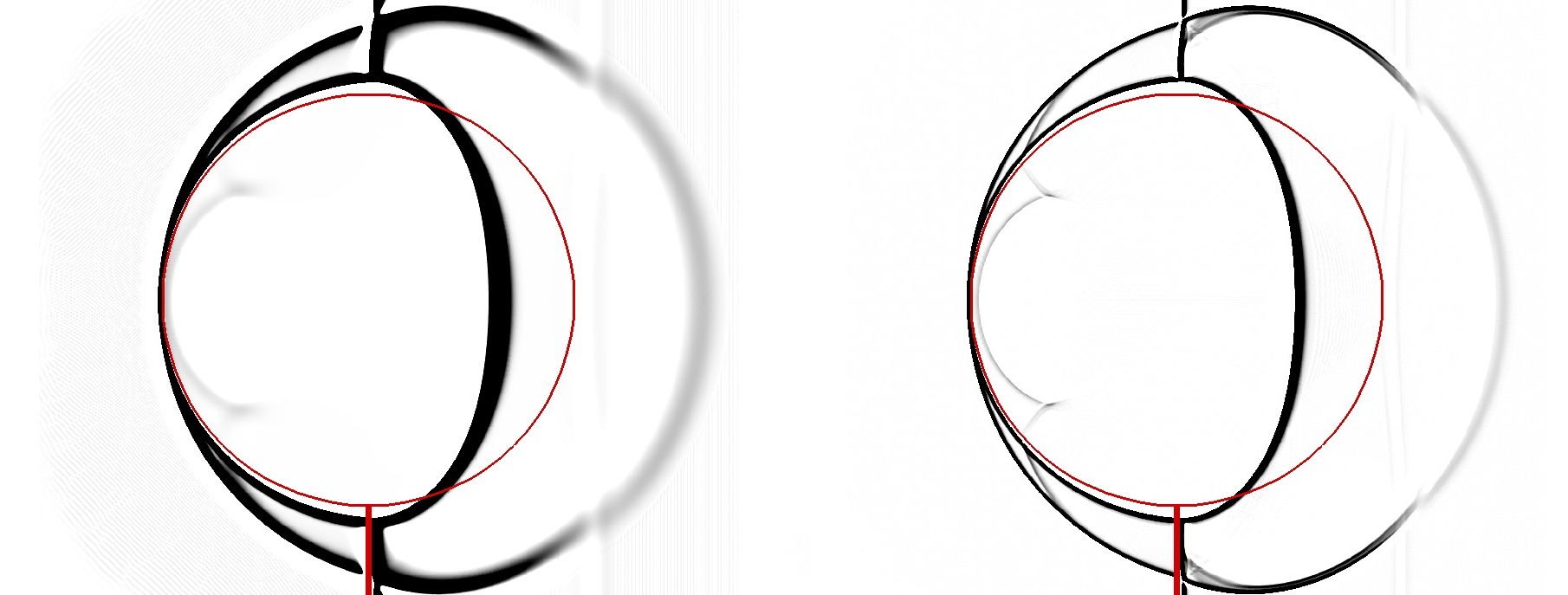
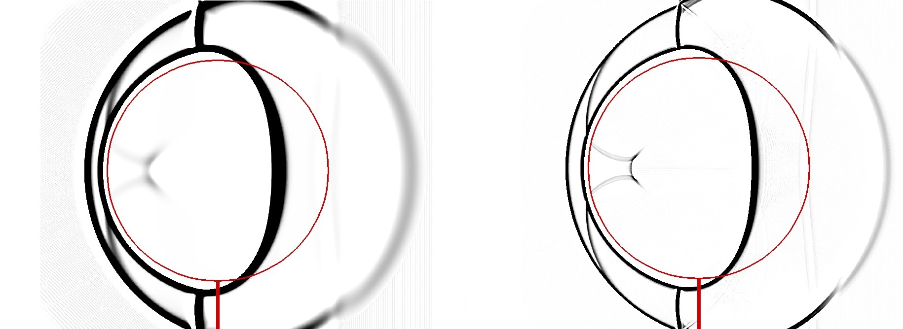
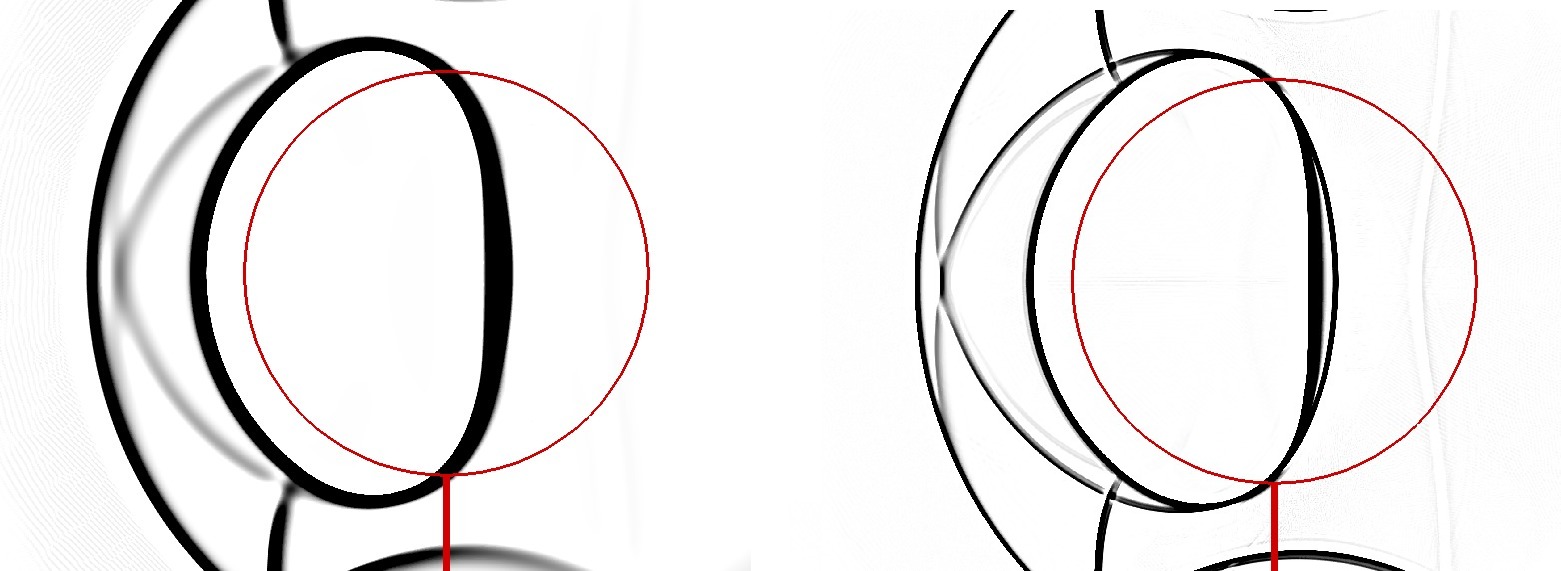
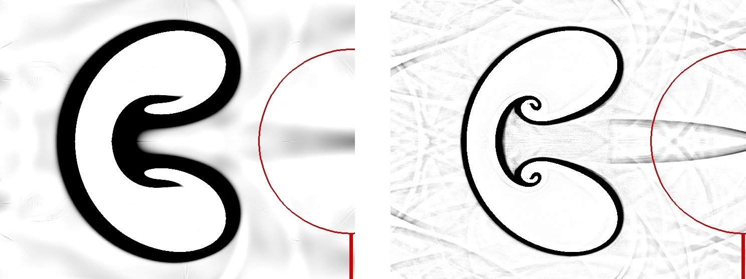
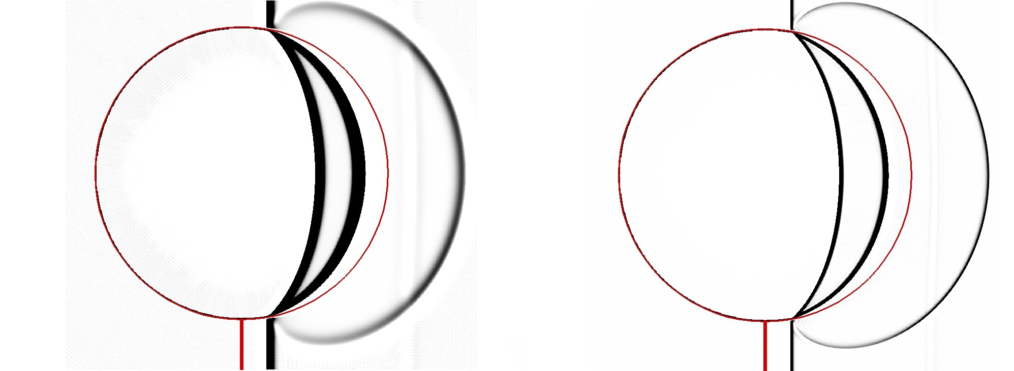
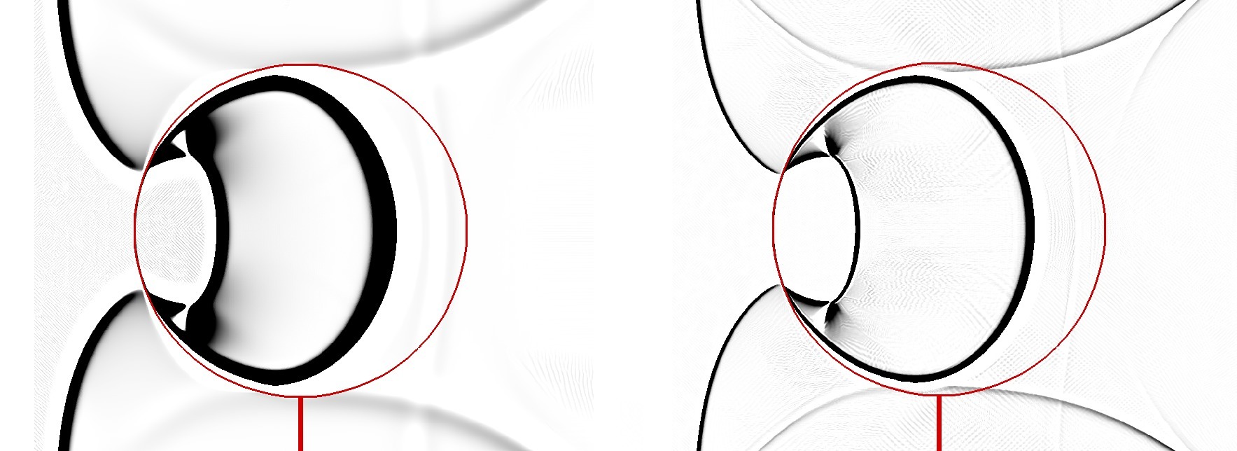
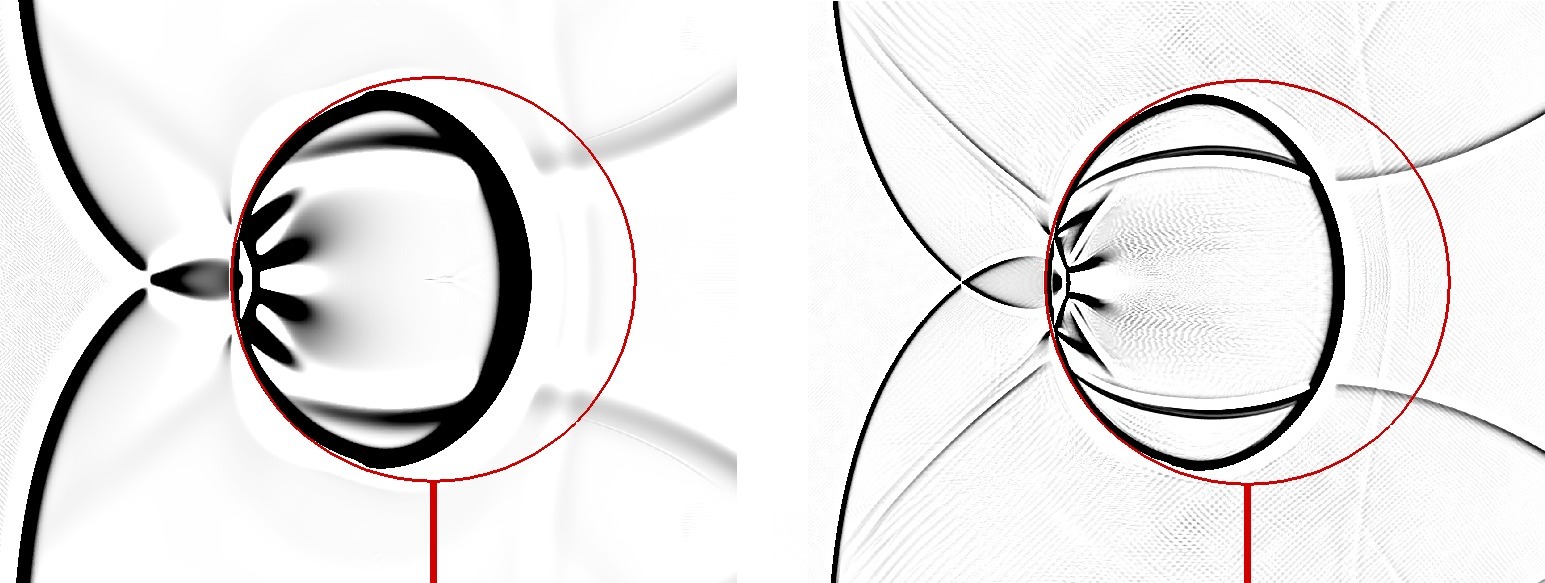
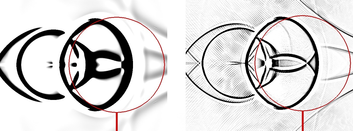
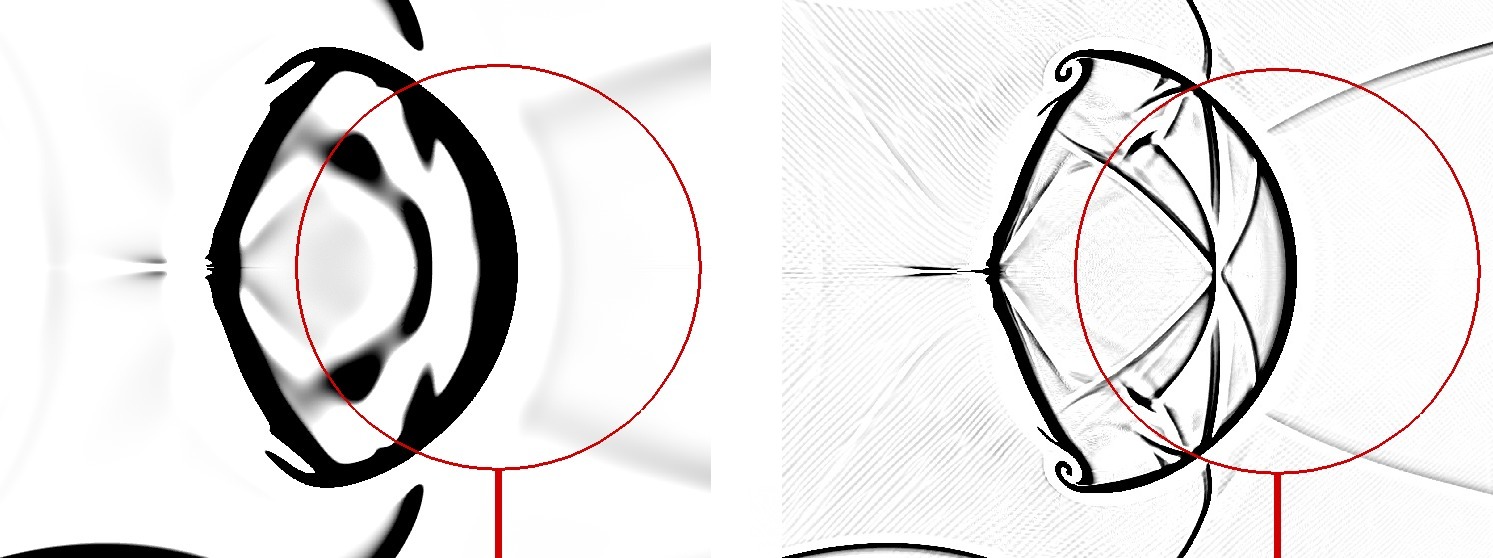
FIG. 7 compares the numerical shadow-graph images of the shock-helium bubble interaction problem by ES-Godunov and ES-GRP(), corresponding to the experiments at different times in Ref. Haas and Sturtevant, 1987. In order to better compare the results, the initial interface (red curves) is added to the numerical shadow-graph images. FIG. 7(a) shows the incident and reflected shock waves outside the bubble and a transmitted shock wave inside after the interaction between the shock and the right side of the bubble. Since the sound speed of the helium-air mixture inside the bubble is much greater than the sound speed of air outside, the transmitted shock wave propagates faster than the incident shock wave and reaches the left boundary of the bubble at experimental time s as shown in FIG. 7(b). Then two secondary transmitted shock waves, connecting the primary transmitted shock wave and the left interface, are seen outside the bubble in FIG. 7(c). The secondary transmitted shock waves intersect each other on the centerline and the internal reflected wave has diverged in FIG. 7(d). Afterwards, the material interface continues to deform in FIGs. 7(e) and (f). FIG. 8 shows the shadow-graph image of the whole flow field at s. It is observed that the primary transmitted wave is convex forward the helium bubble, which means the physical phenomenon that the helium bubble acts as a divergent lens for the incident shock.
(a)
(b)
(c)
(d)
(e)
(f)


Moreover, FIG. 9 compares the numerical shadow-graph images of the shock-R22 bubble interaction problem by ES-Godunov and ES-GRP(). FIG. 9(a) shows the incident and reflected shock waves outside the bubble and a refracted shock wave inside after the interaction between the shock and the right side of the bubble. As the sound speed of R22 in the bubble is much smaller than the sound speed of air outside, the refracted shock wave inside the bubble propagates more slowly than the incident shock wave outside. In FIG. 9(b) the incident shock wave diffracts outside the cylinder and connects to the refracted wave inside the bubble. After then, the two branches of the diffracted waves cross each other and the refracted shock focuses near the interface in FIG. 9(c). Then it expands radially outside the bubble in FIG. 9(d). High velocity created by the transmitted shock at its focus causes a central wedge to form on the downstream R22-air interface in FIG. 9(e). Finally, the interface deforms into a large vortex pair in FIG. 9(f). FIG. 10 shows the shadow-graph image of the whole flow field at s. It is observed that the primary transmitted wave is concave forward the R22 bubble, which acts as a convergent lens for the incident shock. The numerical shadow-graph images show a very good agreement between the second-order numerical simulations and the laboratory experiments. As ES-GRP is used, there are less instability along the material interface than the numerical results in Ref. Quirk and Karni, 1996 and much clearer discontinuity surfaces are observed than those by ES-Godunov.
We continue to simulate this shock-helium bubble interaction problem for various incident Mach numbers in the range of . We use the same amount of grids () as the previous work in Ref. Bagabir and Drikakis, 2001. With the Mach numbers increasing, the accelerations of the bubbles also increase. Numerical results with by the ES-GRP() is presented in FIG. 11. Using the definition of the time scale , where is the sound-speed of ambient air and is the radius of the bubbles, we can compare the current numerical results with those in Ref. Bagabir and Drikakis, 2001 at , where the real computational time corresponds to the first impact of the shock with the bubble. We observe that differences are that there are clearer interfaces of the helium bubble with high by ES-GRP() and no oscillation is produced at the interface.


V.5 Shock-accelerated gas cylinders
This non-oscillatory conservative scheme, effectively simulating the behavior of a single bubble, should be able to simulate multiple bubbles. Now we consider another example in Refs. Tomkins et al., 2003; Kumar et al., 2005, where a planar shock wave accelerates multiple gas SF6 cylinders surrounded by ambient air. The corresponding numerical simulations for different shapes of initial configurations were displayed in Ref. Kumar et al., 2007. The initial configuration of the gas cylinders located at is showed in FIG. 12 at the first instant of the shock and gas cylinders collision , where is used to normalize the time. In the initial configuration of cylinders, the spacing between the centers of the cylinders is , where is the diameter of the cylinders at the experimental nozzle. The numerical initial mass fraction of SF6 in the circular mixing region is described byShankar, Kawai, and Lele (2010)
fitting experimental measurement in Ref. Tomkins et al., 2008, where is the distance to the center of the circle, , is the maximum mass fraction of SF6 measured before the shock impact. We use the reverse computational domain in FIG. 6 with composed of square cells and the position of initial shock is located at . The all boundaries are non-reflective. Air outside and gas mixture inside the circulars are assumed initially to be in atmospheric pressure, and the density and ratio of specific heats for air and SF6 are set in Table 3, which are taken from Ref. Fan et al., 2012. To ensure that the SF6 stays in the computational domain, a uniform velocity of pre-shock gases is set to .
| Gas | Air | SF6 |
|---|---|---|
(a)

(b)

(c)

(d)

In comparison with the experimental results in Ref. Kumar et al., 2005, the numerical results by ES-GRP() in FIG. 12 shows perfectly consistent shapes of the density results, where the time scales are: (a), (b), (c) and (d). In FIG. 12(a), two vortex pairs are formed as a result of shock interaction with the two gaseous cylinders. At , the material interface starts to roll up inside the vortex cores. Similarly in FIG. 12(b), two vortices in opposite directions form. The two inner vortices are weaker than the outer vortices because the density gradients are smaller due to diffusion between the cylinders. In FIG. 12(c), the inner vortices of the right two cylinders are weaker and the inner gas is pushed upstream. In FIG. 12(d), the gas in the left cylinder stretches in the span-wise direction, forming a bridge between the two outer vortex pairs. This bridge elongates with time, eventually breaks up.
VI Conclusions
The study of compressible multi-fluid flows is an important topic in theory, numerics and applications, which can be seen from the very incomplete references quoted here. The researches were carried out in various ways such as physical experiments, physical modelings, numerical simulations and many others. In the present study, we focus on the analysis and design of numerical algorithms with numerical demonstrations based on a typical four-equation model. Certainly, the algorithms proposed here are compatible with the five-equation models Allaire, Clerc, and Kokh (2002) and could be extended to more complex equations of state (EOS) Menikoff and Plohr (1989).
The schemes we design are based on the Godunov scheme with an second order extension by using the GRP solver. The positivity preserving of mass fractions and volume fractions is pivotal as a numerical fluid mixing rule around interfaces, for which the hypotheses of equal partial pressures and no internal energy exchange are made and the exchange of kinetic energy is processed in the current scheme so that no pressure oscillations arise from material interfaces, even though there is large density or temperature difference. Full conservation of our scheme can insure the correct simulation of shock waves or rarefaction waves near the material interfaces.
A series of benchmark problems are tested in order to demonstrate the effectiveness and performance of the current method. The one-dimensional problems display the better resolution of shock waves and the correct computation of internal energy around material interfaces. The two-dimensional shock-bubble interaction problems demonstrate the performance of ES-GRP capturing material interfaces, through the comparison with the corresponding physical experiments. It is expected that this method can be applied to engineering problems practically.
Acknowledgements.
Jiequan Li’s research work is supported by NSFC with Nos. 11771054 and 11371063, and by Foundation of LCP.References
- Abgrall and Karni (2001) R. Abgrall and S. Karni, “Computations of Compressible Multifluids,” J. Comput. Phys. 169, 594–623 (2001).
- Chern et al. (1986) I. L. Chern, J. Glimm, O. Mcbryan, B. Plohr, and S. Yaniv, “Front tracking for gas dynamics,” J. Comput. Phys. 62, 83–110 (1986).
- Grove and Menikoff (1990) J. W. Grove and R. Menikoff, “Anomalous reflection of a shock wave at a fluid interface,” J. Fluid Mech. 219, 313–336 (1990).
- LeVeque and Shyue (1996) R. J. LeVeque and K.-M. Shyue, “Two-Dimensional Front Tracking Based on High Resolution Wave Propagation Methods,” J. Comput. Phys. 123, 354–368 (1996).
- Holmes, Grove, and Sharp (1995) R. L. Holmes, J. W. Grove, and D. H. Sharp, “Numerical investigation of Richtmyer-Meshkov instability using front tracking,” J. Fluid Mech. 301, 51–64 (1995).
- Cocchi and Saurel (1997) J.-P. Cocchi and R. Saurel, “A Riemann Problem Based Method for the Resolution of Compressible Multimaterial Flows,” J. Comput. Phys. 137, 265–298 (1997).
- Abgrall (1994) R. Abgrall, “How to prevent pressure oscillations in multicomponent flow calculations : a quasi conservative approach,” Tech. Rep. RR-2372 (INRIA, 1994).
- Karni (1994) S. Karni, “Multicomponent Flow Calculations by a Consistent Primitive Algorithm,” J. Comput. Phys. 112, 31–43 (1994).
- Shyue (1998) K.-M. Shyue, “An Efficient Shock-Capturing Algorithm for Compressible Multicomponent Problems,” J. Comput. Phys. 142, 208–242 (1998).
- Banks et al. (2007) J. W. Banks, D. W. Schwendeman, A. K. Kapila, and W. D. Henshaw, “A high-resolution Godunov method for compressible multi-material flow on overlapping grids,” J. Comput. Phys. 223, 262–297 (2007).
- Larrouturou (1991) B. Larrouturou, “How to preserve the mass fractions positivity when computing compressible multi-component flows,” J. Comput. Phys. 95, 59–84 (1991).
- Quirk and Karni (1996) J. J. Quirk and S. Karni, “On the dynamics of a shock-bubble interaction,” J. Fluid Mech. 318, 129–163 (1996).
- Karni (1996) S. Karni, “Hybrid Multifluid Algorithms,” SIAM J. Sci. Comput. 17, 1019–1039 (1996).
- Mulder, Osher, and Sethian (1992) W. Mulder, S. Osher, and J. A. Sethian, “Computing interface motion in compressible gas dynamics,” J. Comput. Phys. 100, 209–228 (1992).
- Allaire, Clerc, and Kokh (2002) G. Allaire, S. Clerc, and S. Kokh, “A Five-Equation Model for the Simulation of Interfaces between Compressible Fluids,” J. Comput. Phys. 181, 577–616 (2002).
- Jenny, Müller, and Thomann (1997) P. Jenny, B. Müller, and H. Thomann, “Correction of Conservative Euler Solvers for Gas Mixtures,” J. Comput. Phys. 132, 91–107 (1997).
- Fedkiw et al. (1999) R. P. Fedkiw, T. Aslam, B. Merriman, and S. Osher, “A Non-oscillatory Eulerian Approach to Interfaces in Multimaterial Flows (the Ghost Fluid Method),” J. Comput. Phys. 152, 457–492 (1999).
- Nourgaliev, Dinh, and Theofanous (2006) R. R. Nourgaliev, T. N. Dinh, and T. G. Theofanous, “Adaptive characteristics-based matching for compressible multifluid dynamics,” J. Comput. Phys. 213, 500–529 (2006).
- Terashima and Tryggvason (2009) H. Terashima and G. Tryggvason, “A front-tracking/ghost-fluid method for fluid interfaces in compressible flows,” J. Comput. Phys. 228, 4012–4037 (2009).
- Colella, Glaz, and E. Ferguson (1989) P. Colella, H. M. Glaz, and R. E. Ferguson, “Multifluid Algorithms for Eulerian Finite Difference Methods,” Preprint (1989).
- Miller and Puckett (1996) G. H. Miller and E. G. Puckett, “A High-Order Godunov Method for Multiple Condensed Phases,” J. Comput. Phys. 128, 134–164 (1996).
- Ton (1996) V. T. Ton, “Improved Shock-Capturing Methods for Multicomponent and Reacting Flows,” J. Comput. Phys. 128, 237–253 (1996).
- Dyadechko and Shashkov (2005) V. Dyadechko and M. Shashkov, “Moment-of-fluid interface reconstruction,” Tech. Rep. (Los Alamos National Laboratory, Oct, 2005).
- Xu (1997) K. Xu, “BGK-Based Scheme for Multicomponent Flow Calculations,” J. Comput. Phys. 134, 122–133 (1997).
- Ahn, Shashkov, and Christon (2009) H. T. Ahn, M. Shashkov, and M. A. Christon, “The moment-of-fluid method in action,” Commun. Numer. Meth. Engng. 25, 1009–1018 (2009).
- Kamm and Shashkov (2009) J. R. Kamm and M. J. Shashkov, “A Pressure Relaxation Closure Model for One-Dimensional, Two-Material Lagrangian Hydrodynamics Based on the Riemann Problem,” Commun. Comput. Phys. (2009).
- Hirt, Amsden, and Cook (1974) C. W. Hirt, A. A. Amsden, and J. L. Cook, “An arbitrary Lagrangian-Eulerian computing method for all flow speeds,” J. Comput. Phys. 14, 227–253 (1974).
- Galera, Maire, and Breil (2010) S. Galera, P.-H. Maire, and J. Breil, “A two-dimensional unstructured cell-centered multi-material ALE scheme using VOF interface reconstruction,” J. Comput. Phys. 229, 5755–5787 (2010).
- Francois et al. (2013) M. M. Francois, M. J. Shashkov, T. O. Masser, and E. D. Dendy, “A comparative study of multimaterial Lagrangian and Eulerian methods with pressure relaxation,” Comput. Fluids 83, 126–136 (2013).
- Saurel et al. (2007) R. Saurel, E. Franquet, E. Daniel, and O. Le Metayer, “A relaxation-projection method for compressible flows. Part I: The numerical equation of state for the Euler equations,” J. Comput. Phys. 223, 822–845 (2007).
- Hou and LeFloch (1994) T. Y. Hou and P. G. LeFloch, “Why nonconservative schemes converge to wrong solutions: error analysis,” Math. Comp. 62, 497–530 (1994).
- Ben-Artzi, Li, and Warnecke (2006) M. Ben-Artzi, J. Li, and G. Warnecke, “A direct Eulerian GRP scheme for compressible fluid flows,” J. Comput. Phys. 218, 19–43 (2006).
- Ben-Artzi and Falcovitz (2003) M. Ben-Artzi and J. Falcovitz, Generalized Riemann Problems in Computational Fluid Dynamics (Cambridge University Press, 2003).
- Li and Wang (2017) J. Li and Y. Wang, “Thermodynamical effects and high resolution methods for compressible fluid flows,” J. Comput. Phys. 343, 340–354 (2017).
- Chang and Liou (2007) C.-H. Chang and M.-S. Liou, “A robust and accurate approach to computing compressible multiphase flow: Stratified flow model and AUSM+-up scheme,” J. Comput. Phys. 225, 840–873 (2007).
- Abgrall and Karni (2010) R. Abgrall and S. Karni, “A comment on the computation of non-conservative products,” J. Comput. Phys. 229, 2759–2763 (2010).
- Toro (1997) E. F. Toro, Riemann Solvers and Numerical Methods for Fluid Dynamics (Springer, Berlin, Heidelberg, 1997).
- van Leer (1979) B. van Leer, “Towards the ultimate conservative difference scheme. V. A second-order sequel to Godunov’s method,” J. Comput. Phys. 32, 101–136 (1979).
- Haas and Sturtevant (1987) J.-F. Haas and B. Sturtevant, “Interaction of weak shock waves with cylindrical and spherical gas inhomogeneities,” J. Fluid Mech. 181, 41–76 (1987).
- Bagabir and Drikakis (2001) A. Bagabir and D. Drikakis, “Mach number effects on shock-bubble interaction,” Shock Waves 11, 209–218 (2001).
- Tomkins et al. (2003) C. Tomkins, K. Prestridge, P. Rightley, M. Marr-Lyon, P. Vorobieff, and R. Benjamin, “A quantitative study of the interaction of two Richtmyer-Meshkov-unstable gas cylinders,” Phys. Fluids 15, 986–1004 (2003).
- Kumar et al. (2005) S. Kumar, G. Orlicz, C. Tomkins, C. Goodenough, K. Prestridge, P. Vorobieff, and R. Benjamin, “Stretching of material lines in shock-accelerated gaseous flows,” Phys. Fluids 17, 082107 (2005).
- Kumar et al. (2007) S. Kumar, P. Vorobieff, G. Orlicz, A. Palekar, C. Tomkins, C. Goodenough, M. Marr-Lyon, K. P. Prestridge, and R. F. Benjamin, “Complex flow morphologies in shock-accelerated gaseous flows,” Physica D 235, 21–28 (2007).
- Shankar, Kawai, and Lele (2010) S. Shankar, S. Kawai, and S. Lele, “Numerical Simulation of Multicomponent Shock Accelerated Flows and Mixing using Localized Artificial Diffusivity Method,” in 48th AIAA Aerospace Sciences Meeting Including the New Horizons Forum and Aerospace Exposition (American Institute of Aeronautics and Astronautics, 2010).
- Tomkins et al. (2008) C. Tomkins, S. Kumar, G. Orlicz, and K. Prestridge, “An experimental investigation of mixing mechanisms in shock-accelerated flow,” J. Fluid Mech. 611, 131–150 (2008).
- Fan et al. (2012) M. Fan, Z. Zhai, T. Si, X. Luo, L. Zou, and D. Tan, “Numerical study on the evolution of the shock-accelerated SF6 interface: Influence of the interface shape,” Sci. China Phys. Mech. Astron. 55, 284–296 (2012).
- Menikoff and Plohr (1989) R. Menikoff and B. J. Plohr, “The Riemann problem for fluid flow of real materials,” Rev. Mod. Phys. 61, 75–130 (1989).