Design and Experimental Observation of Valley-Hall Edge States in Diatomic-Graphene-like Elastic Waveguides
Abstract
We report on the design and experimental validation of a two-dimensional phononic elastic waveguide exhibiting topological Valley-Hall edge states. The lattice structure of the waveguide is inspired by the diatomic graphene and it is imprinted in an initially flat plate by means of geometric indentations. The indentations are distributed according to a hexagonal lattice structure which guarantees the existence of Dirac dispersion at the boundary of the Brillouin zone. Starting from this basic material, domain walls capable of supporting edge states can be obtained by contrasting waveguides having broken space inversion symmetry (SIS) achieved by using local resonant elements. Our theoretical study shows that such material maps into the acoustic analog of the quantum valley Hall effect (QVHE) while numerical and experimental results confirm the existence of protected edge states traveling along the walls of topologically distinct domains.
I Introduction
In recent years, the study of topological phases of matter Hasan and Kane (2010); Nobelprize.org (2016) has inspired researchers across the most diverse fields of science and engineering. The possibility to design materials capable of achieving ideal levels of transmission even in presence of imperfections and defects would have a profound impact on many practical applications and open the way to the design of innovative devices. While this area of research originated in quantum physics, it recently expanded to include also the acoustic behavior of fluids and solids Wang et al. (2015); Nasha et al. (2015); Khanikaev et al. (2015); Yang et al. (2015); Chen and Wu (2016); Süsstrunk and Huber (2015); Mousavi et al. (2015); He et al. (2016); Lu et al. (2016a, b); Pal and Ruzzene (2017); Vila et al. (2017); Liu and Semperlotti (2017).
In solid state physics, one of the first implementations of topological materials was based on the use of the Quantum Hall Effect (QHE) which exploited an external magnetic field to break time-reversal symmetry (TRS). While in electronic systems the application of a magnetic field is a rather simple way to achieve TRS breaking, in acoustics the process is more complicated due to the intrinsic reciprocal nature of acoustic waves. The first few attempts at breaking TRS in an acoustical system exploited the use of rotating inclusions (such as spinning rotors Wang et al. (2015); Nasha et al. (2015) or fluids Khanikaev et al. (2015); Yang et al. (2015); Chen and Wu (2016)). Later versions of topological acoustic systems were developed based on the acoustic analogue of the Quantum Spin Hall Effect (QSHE) Süsstrunk and Huber (2015); Mousavi et al. (2015); He et al. (2016) which, contrarily to the QHE, required intact TRS. In this latter case, researchers were able to achieve unidirectional edge states topologically protected from back-scattering by creating acoustic pseudo-spins and pseudo-spin-dependent effective fields.
More recently, several studies have investigated the design of topological materials based on broken space-inversion symmetry (SIS). The creation of such edge states cannot be explained by the previously mentioned QHE or QSHE mechanisms. In fact, when only SIS is broken the lattice still possesses a trivial topology within the context of QHE Hasan and Kane (2010); Raghu and Haldane (2008); Ochiai and Onoda (2009) and QSHE Kane and Mele (2005); Sheng et al. (2006). However, due to the large separation in -space of the two valleys (i.e. the Dirac points occurring at the corners of the Brillouin zone, the and symmetry points), valley-dependent topological invariants can be defined and used to classify the topological states of the different lattices. This approach, usually referred to as quantum valley-Hall effect (QVHE), was recently investigated also for application to fluidic and elastic acoustic waveguides Lu et al. (2016a, b); Pal and Ruzzene (2017); Vila et al. (2017); Liu and Semperlotti (2017).
While most of the above studies have concentrated on electromagnetics and acoustics, the theoretical and experimental observation of topologically protected edge states (TPES) in elastic media has been fairly limited due to the unique challenges occurring in these systems. Designs based on QHE need active components (e.g. gyroscopes or fluid circulators) or the application of an external field (e.g. magnetic field) to break time reversal symmetry. This approach makes the system very complex and often difficult to implement in practical applications. On the contrary, QSHE-based designs employ fully passive mechanisms but often results in non-trivial geometric and/or material configurations in order to engineer the band structure that requires a finely tuned double Dirac coneMousavi et al. (2015). The QVHE, however, relies only on breaking the space inversion symmetry, which is relative easier to achieve in elastic systems of practical interest. Only recently Vila et al. Pal and Ruzzene (2017); Vila et al. (2017) reported the first experimental realization of TPES based on QVHE in an elastic medium Vila et al. (2017). Their design exploited a hexagonal truss-like lattice having local masses attached on selected locations in order to break the space inversion symmetry. No further experimental studies are reported in the current literature concerning the use of QVHE for the design of topological elastic waveguides. In particular, while Vila’s work [Vila et al., 2017] proved the feasibility of the QVHE for elastic media, the design and experimental validation concerned only truss-like lattices that are not well-suited for structural applications. Recent studies Zhu and Semperlotti (2013); Semperlotti and Zhu (2014); Zhu and Semperlotti (2014, 2015, 2016, 2017) have suggested that thin-walled metastructures can have important applications to the control of vibrations and structure-radiated sound in lightweight structures, such as those of interest for aerospace applications or, more in general, for high-performance transportation systems. In order to be able to extend topological acoustic designs to this class of applications, the structural waveguides will have to be fully continuous so to be able to sustain distributed loads such as those produced, for example, by aero- or hydrodynamic forces.
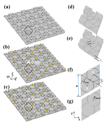
In the present study, we explore and experimentally validate the design of a fully-continuous and load-bearing phononic structural waveguide based on QVHE and capable of one-directional guided modes along the walls of topologically distinct domains. The fundamental design leverages geometric indentations distributed in a graphene-like arrangement within an otherwise flat thin plate. The resulting lattice structure has a symmetry that fully preserves SIS. The symmetry of the lattice can be lowered to by introducing locally-resonant elements located at selected sites. This structure can be considered as an elastic analogue of a diatomic graphene, as shown in Fig. 1a. Depending on the location of the resonant elements, two configurations (later referred to as states) can be defined (Fig.1a and 1b). In the following, we will show that these configurations (that are mirror images of each other) are topologically different and can be contrasted in order to create domain walls able to support topological modes.
We will study the characteristics and behavior of this material via a combination of theoretical, numerical, and experimental results to show that 1) the evolution from one state to the other is accompanied by a topological phase transition, and that 2) edge states are supported along domain walls (DW), that is those interfaces between adjacent phases. In contrast with previous studies, we analyze the dynamic behavior of the QVHE waveguide by using a fully continuum modeling approach which provides a general methodology of analysis and allows mapping the topological behavior to the fundamental massless Dirac equation. We present also an in-depth study of the edge states and of their coupling with both the background material and the states supported by different domain walls. Finally, we experimentally study the propagation of topologically protected edge states in a nearly lossless elastic system and the effect of short range disorder. This analysis would complement and expand the results from previous studies on lossy elastic media Vila et al. (2017) where the higher damping levels does not allow a definitive assessment of the disorder-induced back-scattering.
From a general perspective, we highlight that the proposed waveguide design fully preserves the structural integrity and the load-bearing capabilities of the host medium while, at the same time, it enables a high degree of flexibility in tailoring the topological properties. Such design will open up a broader spectrum of practical applications.
II Numerical Results
II.1 Band Structure Analysis
The fundamental diatomic graphene-like unit cells and their corresponding lattice structures are shown in Fig.1. The unit cell has lattice constant mm, radius mm, and thickness inside the indentation mm. The background medium, i.e. the plate, has thickness mm. The units were assumed to be made out of aluminum having mass density = 2700 , Young’s modulus = 70 GPa, and Poisson’s ratio = 0.33.
In order to break the SIS, we alter one of the indentation by adding a local mass in the form of a cylindrical pillar having radius . In other terms, the initial blind circular hole becomes a blind ring with the same outer radius and thickness. The pillar can be added either to site or (see Fig. 1f), therefore forming two possible material states (see Fig. 1b and 1c) that have the same geometric configuration and are mirror images of each other.
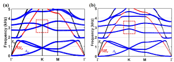
The dispersion relations were calculated using a commercial finite element solver (Comsol Multiphysics). Given the finite dimension of the unit cell in the thickness direction the dispersion curves are composed by symmetric (S), anti-symmetric (A), and shear horizontal (SH) guided Lamb modes. The resulting dispersion curves are shown in Fig.2 where different colors were used to identify the different wave types. Mode hybridization between and modes Zhu and Semperlotti (2015) is clearly observed and it is due to the lack of symmetry of the unit cell with respect to the neutral plane. Although the presence of hybridization does not prevent achieving TPESs, we mention that its occurrence could be avoided by employing symmetric taper configurations with respect to the neutral plane. We specifically pursued a single-sided design for the taper because it yields more general configurations and illustrates how topological properties could be effectively obtained while maintaining a fully flat surface. This latter aspect has important implications in applications where the aerodynamic character of the thin panel must be preserved.
The analysis of the dispersion properties in Fig.2a reveals the existence of a degeneracy at the point from which locally linear and isotropic dispersion curves emanate. In space the curves identify two cones that touch at their vertices at the frequency corresponding to the degeneracy. The cone-like dispersion structure is the Dirac Cone (DC) while the degeneracy is the Dirac Point (DP). This phenomenon is a direct consequence of the lattice symmetry, therefore implying that the DC is protected by the lattice configuration. When the symmetry is lowered to by introducing a resonant pillar (either at site A or B), the SIS is broken and the DP degeneracy is lifted giving rise to a complete bandgap for modes. This mechanism is illustrated in Fig. 2b that shows the band structure of the SIS-broken lattice (for either the A- or B-state). In these simulations, a radius mm of the pillar was used. Note that the larger the wider the topological bandgap that opens up at the degeneracy. It should be kept in mind that larger perturbations of the original geometry also result in stronger inter-valley mixing which ultimately deteriorates the immunity of the edge modes from backscattering. This specific aspect will be further addressed in later sections.
II.2 Berry curvature and valley Chern number
The and state lattices belong to different topological phases Liu and Semperlotti (2017) and can be assembled together in a single lattice in order to enforce a topological phase transition along the wall separating them. In such case, when moving across the transition from one state to the other the topological bandgap would first vanish and then reopen again when entering the opposite state. The topological nature of this transition can be characterized using a topological invariant known as the Chern number .
The parameter is obtained by integrating the Berry curvature of the mode throughout the first Brillouin zone. For this system, is expected to be zero due to an odd distribution of the Berry curvature in -space, which should be expected given that TRS is preserved Hasan and Kane (2010). It follows that these lattices are classified as topologically trivial in the context of QHE systems. Nevertheless, for perturbative SIS breaking the Berry curvature peaks in correspondence to the valleys (i.e. around the and symmetry points), having the form Xiao et al. (2007)
| (1) |
where is the wavevector deviation form the corresponding valley point, is the group velocity at the valley point, and indicates the strength of the SIS breaking (i.e. it is directly correlated to the size of the cylindrical pillar). The sign depends on the choice of the state, of the valley point, and of the mode emanating from the DC. The integral of the Berry curvature can be analytically calculated to be , as the bounds of the integral extend to infinity. This value is independent of the parameters and . In such case, it is possible to define another topological invariant defined in the neighborhood of the valley that is known as the valley Chern number . The of the band is defined as
| (2) |
where the integral bounds extend only to a limited area around the valley. When the SIS breaking term is small, the Berry curvature is strongly localized around the valley and the integral converges quickly (i.e. in a small area around the valley) to a value . This quantized value characterizes the bulk–edge correspondence Yao et al. (2009) while the difference between the valley Chern numbers of the upper (or lower) bands of two adjacent lattices indicates the number of gapless edge states expected at the domain wall. This analysis suggests that an edge state should be expected at the DW between adjacent - and -state lattices, because their corresponding Berry curvatures result in .
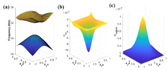
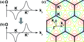
Using Eqn. (1), we carried out the numerical calculation of the Berry curvature of the -state lattice, for both the upper and lower mode. The calculation was performed over a finite squared area around the point with , as shown in Fig. 3b, and the resulting Berry curvature was integrated to obtain the valley Chern numbers. The resulting valley Chern numbers are 0.35 for both the upper and lower mode, that is approximately 30% error from the theoretical quantized value 1/2. The reason for this discrepancy is found in the relatively strong SIS-breaking that was applied to the lattice. In the case of strong symmetry breaking, increases in Eqn. (1) which results in a broader (less localized) distribution of the Berry curvature function around the point. It follows that, not only the integral of converges slower, but the Berry curvature extends across the inter-valley center ( point). This over-extension of the Berry curvature cancels out the Berry curvature with opposite sign (associated with the neighboring valley) as shown in Fig. 4(a,b). In a 2D -plane view, it is also observed that the Berry curvature contours evolve from circular- to triangular-shaped when moving from the valley centers towards the bisectors of the valleys, where the Berry curvature vanishes. This analysis clarifies why the calculated valley Chern number is always less than its expected quantized value and highlights that in presence of strong SIS-breaking the valley Chern number is not uniquely defined. Nevertheless, we note that the calculated value of still provides useful insights with regards to the characterization of the lattice structure. The strong SIS-breaking also leads to edge states that do not cross completely the topological band gap and that are subject to weak reflections when traveling along sharp corners (i.e. in conditions of high-disorder), as shown in later sections.
II.3 Domain-wall edge states
The analysis presented above indicates that by connecting - and -state lattices along selected edges of the graphene-like lattice (i.e., zigzag, armchair, bearded) topologically protected edge states should be expected along the DW interface. In the following, we present the case of domain walls assembled from zigzag edges as an example of possible topological lattices obtainable from the fundamental states.
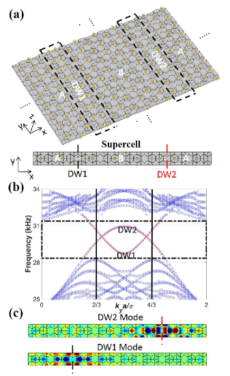
Figure 5a shows the schematic of an elastic waveguide assembled by connecting - and -state lattices along their zigzag edge. Two different types of domain walls are formed at the interface between the two states, as marked by the black dashed box. These two types of DW have different geometric configurations depending on the position of the - and -states with respect to the interface. For clarity, these two configurations are labeled DW1 (-state is on the right of the -state) and DW2 (-state is on the right of the -state). The schematic of the primitive supercell of the composite waveguide is provided in Fig. 5a. This supercell was used in the numerical calculations in order to obtain the dispersion properties of the composite waveguide. More specifically, periodic boundary conditions were applied on the four sides of the supercell before solving for the system eigenvalues. Figure 5b shows the dispersion relations of such waveguide in a frequency range around the topological bandgap (only the modes are plotted).
The appearance of the edge states at DW1 and DW2 can be easily identified in the dispersion results (Figure 5b) where the bulk modes are marked in blue and the edge modes in red. The solid black vertical lines mark the projections of the valley points along the direction of the interface ( maps to 2/3 and to 4/3). Note that the forward propagating mode supported by DW1 (DW2) emanates from the () valley while the backward propagating mode supported by DW1 (DW2) emanates from the () valley. Such large separation in momentum space between the forward and backward traveling modes enables edge states that are almost completely immune from back-scattering, at least in presence of long range disorder. It is also worth observing that the two DW modes are partially gapped (i.e. they do not cross entirely the topological band) due to the large perturbation produced in the original lattice. Examining the eigenstates associated to these edge modes (Fig.5c), we observe that they exhibit different symmetry with respect to the plane of the interface (indicated by the dashed lines in Fig.5c). In the following, we will show that this aspect leads to different coupling behavior when the edge states are excited by an external source.
II.4 Full field numerical simulations
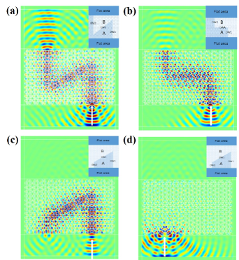
In order to further characterize the propagation behavior of the egde modes, we performed full field numerical simulations on a flat plate having the QVHE topological lattice embedded in the center section. The lattice was excited from a source located in the flat part of the plate (hence external to the topological material) and generating a plane wave at normal incidence. This general configuration was used to investigate the dynamic behavior of different types of DW interfaces. The different interfaces are classified according to the edge-type of the graphene lattice used to assemble the domain wall. In particular, DW1 and DW2 are walls obtained between zigzag edges, and DWA is a wall between armchair edges. Figure 6 provides a schematic view of these domain wall configurations. Numerical results are shown in Fig.7 for the steady-state response due to an excitation at 29.93 kHz. Perfectly matched layers were applied all around the structure to suppress the boundary reflections. The inset in each sub-figure indicates the domain wall shape being investigated as well as the specific nature of the wall (DW1, DW2, or DWA).
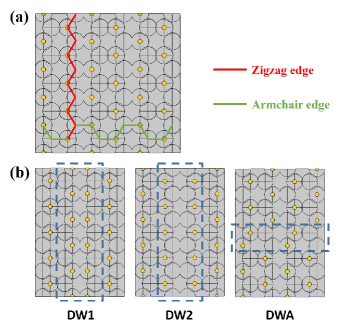
Figure 7a shows a Z-shape domain wall whose constitutive segments are all made of DW1 type (i.e. zigzag edge) and form two sharp corners having bends. The numerical results show that the input wave (see white arrow) generates an edge state that is concentrated near the DW and is effectively guided along the wall itself. The transmitted beam appears to have lower intensity compared to the incident beam due to the impedance mismatch between the topological lattice and the flat plate which produces some reflections at both the entrance and exit points. Figure 7b shows the case of a domain wall characterized by two bends. This case is different from the former because the mid-segment of the domain wall has armchair edges which theoretically should support a different edge state. This case was explored in order to understand if propagation along dissimilar and concatenated domain walls was possible. Results clearly illustrate the efficient coupling between the zigzag and the armchair edge states, as long as both modes are supported at the same excitation frequency. In Fig.7c and d, the domain wall is designed to perform a U-turn. Although, in this case, the individual segments are all of zigzag type, the design mixes DW1 and DW2 along the same interface. This aspect is important because it was previously shown that DW1 and DW2 support edge modes having different symmetry with respect to the interface.
When the interface is excited on the DW1 interface (Fig.7c), which supports symmetric eigenstates, the edge mode can be excited and propagate along the domain wall. On the contrary, when the excitation is applied at DW2 (Fig.7d), which supports antisymmetric eigenstates, the incident wave cannot enter the topological interface and it is entirely reflected. This behavior clearly shows the different levels of coupling existing between an external excitation and the different types of domain walls. It also offers a higher flexibility in the design of waveguides having preferential and one-way coupled direction of propagations.
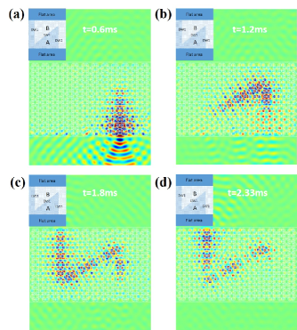
To further characterize the propagation behavior of the different edge states, we performed a time transient simulation on the same structure used in Fig.7a. The main objective was to observe the back-scattering immune behavior of the edge states. A 20-count wave burst having a center frequency of 29.93 kHz was used as excitation. Figure 8 shows snapshots of the propagating wave at successive time instants. Results clearly illustrate how the wave burst is capable of traveling around sharp bends while giving rise only to small amount of back-scattered waves. Note that this result is fully consistent with our previous theoretical analysis that showed a small but nonetheless non-negligible inter-valley mixing between the two counter-propagating edge modes.
III Experimental Results
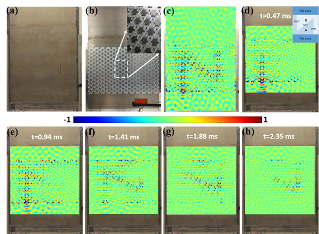
In order to validate our theoretical and numerical approach to the design of topological waveguides, we performed an experimental validation of one of the designs discussed above. In particular, we selected the Z-shaped interface with segments aligned with the DW1 zigzag edges. The experimental sample was fabricated by CNC machining starting from an initially flat aluminum plate having a thickness of mm (Fig.9b). The experimental sample was mounted vertically in an aluminum frame while viscoelastic tape was applied on the surrounding boundaries in order to minimize reflections and reverberation (Fig.9a). An array of Micro Fiber Composite (MFC) patches (Fig.9b) was surface bonded on the plate in correspondence to the entrance of the zigzag edge and actuated to generate a quasi- plane wave. The number of MFC patches was selected in order to generate a wavefront wide enough to excite the entire Z-shaped channel. The out-of-plane response of the plate was acquired using a Polytec PSV-500 scanning laser vibrometer on the flat side. Both steady-state and transient measurements were performed. The steady-state response was collected following a harmonic excitation at kHz which belongs to the topological bandgap. The time transient measurement was obtained in response to a 15-count wave-burst excitation signal having a kHz center frequency. In this experimental study, we selected a lower number of counts for the wave burst signal compared with the numerical simulations in order to reduce the length of the burst signal and therefore better visualizing the propagation along the corners and any eventual backscattering.
Figure 9c shows the experimental measurements under steady-state excitation. The topological edge state along the Z-shaped domain wall is clearly visible accompanied by a very limited penetration of energy into the bulk, as predicted by both theory and simulations. Following the same approach set in place for the numerical simulations, a time transient measurement was also performed in order to observe the possible presence of back-scattering at the sharp corners. Figure 9d-h show the flexural wave measured at successive time instants. Results clearly indicate that the wave burst is capable of traveling along the Z-shaped path while giving rise only to minor back-scattering. Note that the transient excitation tends to generate a wider spectrum of frequencies in the initial burst. Hence, in order to eliminate the initial broadband transient the measured data were bandpass filtered around the center frequency of the burst.
As a general observation, these results are well consistent with the theoretical and numerical predictions and confirm the possibility to create fully-continuous, load-bearing structural waveguides exhibiting high-level topological properties.
IV Conclusions
We presented the design and the experimental validation of a fully-continuous and load-bearing thin-walled structural waveguide capable of topologically protected elastic modes. The waveguide was designed by exploiting a concept that is the elastic analogue of the Quantum Valley Hall Effect (QVHE) achieved via a diatomic-graphene-inspired design implemented by using only geometric tapers. Such design preserves the structural properties of the host waveguide while providing a largely increased design space capable of a highly enhanced tailoring of the energy propagation properties. The diatomic graphene design exhibits a symmetry which breaks the mirror symmetry characteristic of monoatomic graphene . The reduced symmetry guarantees the existence of topologically protected edge waves at the interface between domains having different topological charges. Despite the QVHE effect can only give rise to weak topological properties (because time reversal symmetry is still intact), topological edge states having a substantially reduced back-scattering can be achieved.
This approach enables the design of simple and robust elastic topological waveguides that can be fully embedded in a host structure in order to achieve precise and (quasi) one-directional wave guiding. This approach holds great potential to control the propagation of acoustic waves within structural elements which is a critical capability to enable passive-adaptive vibration and structure-borne noise control in structural systems for high-performance applications.
V Acknowledgments
The authors gratefully acknowledge the financial support of the Air Force Office of Scientific Research under the grant YIP FA9550-15-1-0133.
References
- Hasan and Kane (2010) M. Z. Hasan and C. L. Kane, Rev. Mod. Phys. 82, 3045 (2010).
- Nobelprize.org (2016) Nobelprize.org, “The 2016 nobel prize in physics - press release,” (2016).
- Wang et al. (2015) P. Wang, L. Lu, and K. Bertoldi, Phys. Rev. Lett. 115, 104302 (2015).
- Nasha et al. (2015) L. M. Nasha, D. Klecknera, A. Reada, V. Vitellib, A. M. Turnerc, and W. T. M. Irvine, Proc. Natl. Acad. Sci. U.S.A. 112, 14495 (2015).
- Khanikaev et al. (2015) A. B. Khanikaev, R. Fleury, S. H. Mousavi, and A. Alu, Nat. Comms. 6, 8260 (2015).
- Yang et al. (2015) Z. Yang, F. Gao, X. Shi, X. Lin, Z. Gao, Y. Chong, and B. Zhang, Phys. Rev. Lett. 114, 114301 (2015).
- Chen and Wu (2016) Z.-G. Chen and Y. Wu, Phys. Rev. Appl. 5, 054021 (2016).
- Süsstrunk and Huber (2015) R. Süsstrunk and S. D. Huber, Science 349, 47 (2015).
- Mousavi et al. (2015) S. H. Mousavi, A. B. Khanikaev, and Z. Wang, Nat. Commun. 6, 8682 (2015).
- He et al. (2016) C. He, X. Ni, H. Ge, X.-C. Sun, Y.-B. Chen, M.-H. Lu, X.-P. Liu, and Y.-F. Chen, Nat. Phys. 12, 1124 (2016).
- Lu et al. (2016a) J. Lu, C. Qiu, M. Ke, and Z. Liu, Phys. Rev. Lett. 116, 093901 (2016a).
- Lu et al. (2016b) J. Lu, C. Qiu, L. Ye, X. Fan, M. Ke, F. Zhang, and Z. Liu, Nat. Phys. 13, 369 (2016b).
- Pal and Ruzzene (2017) R. K. Pal and M. Ruzzene, New Journal of Physics 19, 025001 (2017).
- Vila et al. (2017) J. Vila, R. K. Pal, and M. Ruzzene, Phys. Rev. B 96, 134307 (2017).
- Liu and Semperlotti (2017) T.-W. Liu and F. Semperlotti, arXiv preprint arXiv:1708.02987 (2017).
- Raghu and Haldane (2008) S. Raghu and F. D. M. Haldane, Phys. Rev. A 78, 033834 (2008).
- Ochiai and Onoda (2009) T. Ochiai and M. Onoda, Phys. Rev. B 80, 155103 (2009).
- Kane and Mele (2005) C. L. Kane and E. J. Mele, Phys. Rev. Lett. 95, 146802 (2005).
- Sheng et al. (2006) D. N. Sheng, Z. Weng, L. Sheng, and F. D. M. Haldane, Phys. Rev. Lett. 97, 036808 (2006).
- Zhu and Semperlotti (2013) H. Zhu and F. Semperlotti, AIP Advances 3, 092121 (2013).
- Semperlotti and Zhu (2014) F. Semperlotti and H. Zhu, Journal of Applied Physics 116, 054906 (2014).
- Zhu and Semperlotti (2014) H. Zhu and F. Semperlotti, Journal of Applied Physics 116, 094901 (2014).
- Zhu and Semperlotti (2015) H. Zhu and F. Semperlotti, Phys. Rev. B 91, 104304 (2015).
- Zhu and Semperlotti (2016) H. Zhu and F. Semperlotti, Phys. Rev. Lett. 117, 034302 (2016).
- Zhu and Semperlotti (2017) H. Zhu and F. Semperlotti, arXiv preprint arXiv:1701.03445 (2017).
- Xiao et al. (2007) D. Xiao, W. Yao, and Q. Niu, Phys. Rev. Lett. 99, 236809 (2007).
- Yao et al. (2009) W. Yao, S. A. Yang, and Q. Niu, Phys. Rev. Lett. 102, 096801 (2009).