Secure Transmission and Self-Energy Recycling for Wireless-Powered Relay Systems with Partial Eavesdropper Channel State Information

Jingping Qiao,  Haixia Zhang,  Feng Zhao, and Dongfeng Yuan J. Qiao (e-mail: qiaojingping@mail.sdu.edu.cn), H. Zhang (e-mail: haixia.zhang@sdu.edu.cn), and D. Yuan (e-mail: dfyuan@sdu.edu.cn) are all with Shandong provincial key laboratory of wireless communication technologies, Shandong University, China. F. Zhao (e-mail:zhaofeng@guet.edu.cn) is with the key laboratory of cognitive radio and information processing, Guilin University of Electronic Technology, China.
Abstract

This paper focuses on the secure transmission of wireless-powered relay systems with imperfect eavesdropper channel state information (ECSI). For efficient energy transfer and information relaying, a novel two-phase protocol is proposed, in which the relay operates in full-duplex (FD) mode to achieve simultaneous wireless power and information transmission. Compared with those existing protocols, the proposed design possesses two main advantages: 1) it fully exploits the available hardware resource (antenna element) of relay and can offer higher secrecy rate; 2) it enables self-energy recycling (S-ER) at relay, in which the loopback interference (LI) generated by FD operation is harvested and reused for information relaying. To maximize the worst-case secrecy rate (WCSR) through jointly designing the source and relay beamformers coupled with the power allocation ratio, an optimization problem is formulated. This formulated problem is proved to be non-convex and the challenge to solve it is how to concurrently solve out the beamformers and the power allocation ratio. To cope with this difficulty, an alternative approach is proposed by converting the original problem into three subproblems. By solving these subproblems iteratively, the closed form solutions of robust beamformers and power allocation ratio for the original problem are achieved. Simulations are done and results reveal that the proposed S-ER based secure transmission scheme outperforms the traditional time-switching based relaying (TSR) scheme at a maximum WCSR gain of 80%percent8080\%. Results also demonstrate that the WCSR performance of the scheme reusing idle antennas for information reception is much better than that of schemes exploiting only one receive antenna.

Index Terms:
Physical layer security, full-duplex relay, energy harvesting, self-energy recycling, imperfect channel state information.

I Introduction

The broadcast nature of wireless medium presents a formidable challenge in ensuring simultaneously secure and reliable communications in the presence of adversaries [1]. To enhance the transmission security, physical layer security, that achieves secrecy by exploiting the inherent randomness of wireless channels, has been proposed recently and drawn intensive attention [2, 3, 4, 5]. A particularly interesting physical layer security technology is cooperative relaying, since it can not only combat the effect of the path loss by shortening the access distance, but also provide extra spatial degrees of freedom for information transmission by coordinating with other communication nodes. Recent studies [6, 7, 8, 9, 10, 11, 12] show that compared with direct transmission schemes, cooperative relaying can bring more than twice the secrecy rate gain. This has made physical layer security one of the potential technologies to protect the security of 5G wireless networks [13].

The performance of cooperative systems is based on the amount of power of relays spent on information transmission. Sometimes, making relay spend more power on information relay is unrealistic. For instance, although the mobile users can be treated as cooperative relays in cellular networks, they may unwilling to participate in cooperative communications because of their starving energy storage. To alleviate this, wireless-powered strategy is proposed by making use of radio-frequency (RF) signals emitted from other communication nodes to provide stable energy supply for relay nodes [14, 15, 16]. With respect to different roles of relays in secure systems, there are two types of cooperative schemes, i.e., wireless-powered cooperative relaying scheme and wireless-powered cooperative jamming scheme. Specifically, with harvested energy from RF signals emitted by the source node or the destination node, cooperative relaying schemes [17, 18, 19, 20] utilize multi-antenna technologies to steer information beams for information enhancement at desired receivers and information leakage degradation at malicious attackers. While for wireless-powered cooperative jamming schemes [21, 22, 23], idle internal communication nodes act as jammers, which consume the harvested energy to transmit jamming signals confusing malicious eavesdroppers. All of the aforementioned work focuses on half-duplex (HD) relaying operation, whereas the spectral efficiency loss from HD constraint leads to system secrecy rate degradation.

As an attractive solution to overcome this limitation of wireless-powered secure systems, wireless-powered full-duplex (FD) architecture has drawn increasing attention in secure systems [24, 25, 26]. In [24], a cooperative jamming scheme was developed for friendly jammers with FD architecture, in which jammer nodes simultaneously harvest energy and transmit jamming signals to degrade eavesdropper channels. Moreover, a novel time switching (TS)-based FD relaying scheme is proposed to enable the secure communications in wireless-powered cooperative systems [25, 26]. Relay nodes adopt available energy harvested in the first phase to assist information transmission in a FD way. Compared with HD operation, FD capable nodes can offer an average of 33%66%percent33percent6633\%-66\% secrecy rate gain. However, the substantial secrecy performance of FD relaying is limited by the introduced loopback interference (LI). Although many advanced interference-cancellation (IC) technologies [27, 28] have been proposed to suppress LI, implementing such technologies needs additional energy consumption and expensive hardwares. A novel self-energy recycling (S-ER) based relaying scheme [29] is proposed and investigated to against the negative effects of LI [30, 31, 32]. Particularly, secure beamforming [30] and antenna assignment [31] schemes are exploited for S-ER based relaying systems, in which the LI energy is recycled and reused for information retransmission. Additionally, as an extension of [30, 31], [32] introduced S-ER strategy into FD source nodes, and proposed an optimal beamforming scheme for efficient energy and confidential information transmission.

The above work on S-ER based secure systems can make use of the energy of LI efficiently to achieve better secrecy rate performance. However, [30, 31, 32] either focus on single antenna transmission from source to relay or secure systems without cooperative relays, leading to limited secrecy enhancement of S-ER relaying schemes. More importantly, the potential performance improvements of above work rely on the perfect eavesdropper channel state information (ECSI), which is an ideal assumption [33]. In general, it is prohibitively difficult for a transmitter to obtain full ECSI, since eavesdroppers are usually keeping silent to hide. Moreover, even eavesdroppers feedback channel estimation results to the transmitter, due to some practical issues such as channel estimation errors, feedback errors, quantization and delays, the feedback information may be untrustworthy and exists some uncertainties [34, 35]. Such kind of uncertainties in turn lead to serious information leakage and secrecy performance degradation.

Motivated by the aforementioned problems, this work focuses on robust secure transmission scheme design for S-ER based wireless-powered relay systems. To facilitate S-ER operation at relay, a two-phase FD relaying protocol is adopted, and separate antenna configuration is considered at the relay node. In particular, half of the time block is devoted for information transmission from source to relay, while the remaining time is used for concurrent information forwarding and energy harvesting. The harvested energy from the LI channel in addition to RF signals emitted from the source can be stored and then used for information retransmission in the next time block. The main objective of this work is to investigate the effect of imperfect ECSI on the system secrecy rate, and design robust beamformers as well as power allocation scheme to degrade the information leakage caused by channel uncertainty, and finally offer more secrecy rate gain. Specifically, the main contributions of this paper can be summarized as follows.

  • A novel two-phase S-ER based secure system is established by adopting FD mode to achieve simultaneous information and power transmission. An antenna reuse approach is proposed to make use of idle transmit antennas for information reception to enhance the information signal strength.

  • The worst-case secrecy rate (WCSR) is introduced as the system secrecy performance metric. To maximize WCSR, a joint optimization problem including information beamformer, transceiver beamformers and power allocation ratio is formulated and investigated under imperfect ECSI.

  • With respect to the information beamformer, the transceiver beamformers and the power allocation ratio, the formulated optimization problem of WCSR is non-convex, and it is prohibitively difficult to solve due to high computational complexity. To cope with this difficulty and solve it efficiently, an alternative method is proposed by converting the original problem into three subproblems. Solving these subproblems iteratively, the closed form solutions of the robust beamformers and the optimal power allocation ratio maximizing WCSR are derived.

  • To demonstrate the superiority of the proposed S-ER based secure system in terms of secrecy performance, the WCSR optimization problem for the traditional time switching based relaying (TSR) systems is also formulated and included as a baseline. Simulations are done and results show that the proposed S-ER based secure systems outperform those TSR systems greatly.

The rest of this paper is organized as follows. Section II describes the system model of the proposed S-ER based secure system and the WCSR optimization problem formulation. Section III elaborates the proposed algorithm to find solutions for the robust beamformers and the power allocation ratio to maximize WCSR performance. The WCSR optimization problem for traditional TSR systems is introduced in Section IV as a benchmark for performance comparisons. Then, Section V simulates and analyzes the performance of the proposed S-ER based secure system. Finally, Section VI concludes all the paper.

Notations: The bold upper (lower) letters denote matrices (column vectors), and ()superscript(\cdot)^{{\dagger}} denotes the conjugate transpose. 𝐈Msubscript𝐈𝑀\mathbf{I}_{M} is the identity matrix of size M×M𝑀𝑀M\times M. 𝔼{}𝔼\mathbb{E}\{\cdot\} denotes expectation, and \|\cdot\| indicates the L2subscript𝐿2L_{2} norm of a vector and the |||\cdot| means the absolute value. [a]+superscriptdelimited-[]𝑎[a]^{+} denotes max(a,0)𝑎0\max(a,0). And 𝒞𝒩(0,σ2)𝒞𝒩0superscript𝜎2\mathcal{CN}(0,\sigma^{2}) represents a circularly symmetric complex Gaussian distribution with zero mean and variance σ2superscript𝜎2\sigma^{2}. N×Msuperscript𝑁𝑀\mathbb{C}^{N\times M} represents the N×M𝑁𝑀N\times M complex vector space.

II System Model and Problem Formulation

II-A System Model

Refer to caption
Figure 1: System model of the wireless-powered FD relay system, where the S-ER strategy is employed at the FD relay.

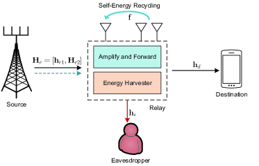
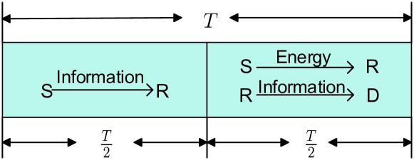
Secure transmission in a wireless-powered relay system is considered, as shown in Fig. 1. In this system, a multi-antenna source transmits confidential signals to a single antenna destination with the help of a wireless-powered relay, while keeping information from being intercepted by an eavesdropper111 Note that it is assumed that the direct link between source and destination (or eavesdropper) does not exist due to the deep shadowing effect in the transmission scenario [17]. . To facilitate simultaneous energy and secure information transmission, a two-phase FD relaying protocol is adopted. As shown in Fig. 2(a), the source node transmits information signals to the relay node in the first phase, while in the second phase, the relay node works in FD mode to forward information and harvest energy concurrently. To enable FD in the second phase, a separate antenna configuration is adopted at relay, i.e., the relay is equipped with one receive antenna and M𝑀M transmit antennas. In the first phase, generally only one receive antenna is used for information reception, while those multiple transmit antennas are idle. To make full use of all the available hardware resources (i.e., idle transmit antennas) of relay node to capture more information, an antenna reuse approach at the relay node is proposed. The detailed architecture is given in Fig. 2(b), where M𝑀M idle transmit antennas are reused for information reception in the first phase.

Refer to caption
(a) Wireless information and power transmission during one time block T𝑇T.
Refer to caption
(b) Time switching architecture for antenna reuse approach at the relay.
Figure 2: SWIPT model and time switching architecture for antenna reuse approach at the wireless-powered relay.

With the antenna reuse approach, the received signal at the relay node during the first phase is written as

𝐲r,1=𝐇r𝐰sxs+𝐧r,subscript𝐲𝑟1superscriptsubscript𝐇𝑟subscript𝐰𝑠subscript𝑥𝑠subscript𝐧𝑟\mathbf{y}_{r,1}=\mathbf{H}_{r}^{{\dagger}}\mathbf{w}_{s}x_{s}+\mathbf{n}_{r}, (1)

where 𝐲r,1(M+1)×1subscript𝐲𝑟1superscript𝑀11\mathbf{y}_{r,1}\in\mathbb{C}^{(M+1)\times 1}, 𝐰sxssubscript𝐰𝑠subscript𝑥𝑠\mathbf{w}_{s}x_{s} denotes confidential information signal transmitted from source node with 𝔼{|xs|2}=Ps𝔼superscriptsubscript𝑥𝑠2subscript𝑃𝑠\mathbb{E}\{|x_{s}|^{2}\}=P_{s}, and 𝐰ssubscript𝐰𝑠\mathbf{w}_{s} represents the information beamforming vector at the source node with unit power 𝔼{𝐰s2}=1𝔼superscriptnormsubscript𝐰𝑠21\mathbb{E}\{\|\mathbf{w}_{s}\|^{2}\}=1. The channel from source to relay 𝐇r=[𝐡r1,𝐇r2]subscript𝐇𝑟subscript𝐡𝑟1subscript𝐇𝑟2\mathbf{H}_{r}=[\mathbf{h}_{r1},\mathbf{H}_{r2}] is assumed to be perfectly known to legitimate nodes, where 𝐡r1N×1subscript𝐡𝑟1superscript𝑁1\mathbf{h}_{r1}\in\mathbb{C}^{N\times 1} and 𝐇r2N×Msubscript𝐇𝑟2superscript𝑁𝑀\mathbf{H}_{r2}\in\mathbb{C}^{N\times M} represent channel coefficients from source to receive antenna and those transmit antennas at relay, respectively. Moreover, 𝐧rsubscript𝐧𝑟\mathbf{n}_{r} denotes the additive white Gaussian noise (AWGN) at relay, i.e., 𝐧r𝒞𝒩(0,N0𝐈M+1)similar-tosubscript𝐧𝑟𝒞𝒩0subscript𝑁0subscript𝐈𝑀1\mathbf{n}_{r}\sim\mathcal{CN}(0,N_{0}\mathbf{I}_{M+1}).

In the second phase, to enable simultaneous wireless information and power transfer, the relay node works in FD mode. Different from traditional FD relaying protocols, the LI caused by FD operation is beneficial, since it is also a power source for the energy-constrained relay and enables the relay to reuse its own transmitted energy. This mode is the previously described S-ER [29, 31]. Therefore, adopting S-ER protocol at relay, no extra energy and hardware resources needed any more to suppress the LI. Moreover, the energy of LI can be harvested together with the energy signal emitted from the source, i.e.,

yr,2=𝐡r1𝐰Hxp+𝐟𝐰txr+nr,H.subscript𝑦𝑟2superscriptsubscript𝐡𝑟1subscript𝐰𝐻subscript𝑥𝑝superscript𝐟subscript𝐰𝑡subscript𝑥𝑟subscript𝑛𝑟𝐻y_{r,2}=\mathbf{h}_{r1}^{{\dagger}}\mathbf{w}_{H}x_{p}+\mathbf{f}^{{\dagger}}\mathbf{w}_{t}x_{r}+n_{r,H}. (2)

On the right-hand side of equation (2), the first part is the energy signal from the source node, where 𝐰Hsubscript𝐰𝐻\mathbf{w}_{H} denotes the energy beamformer with 𝔼{𝐰H2}=1𝔼superscriptnormsubscript𝐰𝐻21\mathbb{E}\{\|\mathbf{w}_{H}\|^{2}\}=1, and xpsubscript𝑥𝑝x_{p} is the energy signal emitted from the source with power 𝔼{|xp|2}=Ps𝔼superscriptsubscript𝑥𝑝2subscript𝑃𝑠\mathbb{E}\{|x_{p}|^{2}\}=P_{s}. Additionally, the second part represents the LI signal, wherein 𝐟𝐟\mathbf{f} denotes the LI channel between antennas at FD relay and is normally regarded as Rayleigh fading channel [9, 36]. While 𝐰txrsubscript𝐰𝑡subscript𝑥𝑟\mathbf{w}_{t}x_{r} represents the retransmit signal with 𝔼{|xr|2}=Pr𝔼superscriptsubscript𝑥𝑟2subscript𝑃𝑟\mathbb{E}\{|x_{r}|^{2}\}=P_{r}, and 𝐰tM×1subscript𝐰𝑡superscript𝑀1\mathbf{w}_{t}\in\mathbb{C}^{M\times 1} is the transmit beamforming vector at the relay with 𝔼{𝐰t2}=1𝔼superscriptnormsubscript𝐰𝑡21\mathbb{E}\{\|\mathbf{w}_{t}\|^{2}\}=1. Besides, as the energy transmission between source and relay can be seen as a MISO (Multi-Input Single-Output) system, MRT (Maximum Ratio Transmission) is employed as the energy beamformer, i.e., 𝐰H=𝐡r1𝐡r1subscript𝐰𝐻subscript𝐡𝑟1normsubscript𝐡𝑟1\mathbf{w}_{H}=\frac{\mathbf{h}_{r1}}{\|\mathbf{h}_{r1}\|}. Then, the harvested energy is written as

EH=T2η(|𝐡r1𝐰H|2Ps+|𝐟𝐰t|2Pr).subscript𝐸𝐻𝑇2𝜂superscriptsuperscriptsubscript𝐡𝑟1subscript𝐰𝐻2subscript𝑃𝑠superscriptsuperscript𝐟subscript𝐰𝑡2subscript𝑃𝑟E_{H}=\frac{T}{2}\eta(|\mathbf{h}_{r1}^{{\dagger}}\mathbf{w}_{H}|^{2}P_{s}+|\mathbf{f}^{{\dagger}}\mathbf{w}_{t}|^{2}P_{r}). (3)

where η𝜂\eta is the energy harvesting efficiency, 0<η10𝜂10<\eta\leq 1, which depends on the rectification process and the energy harvesting circuitry [15]. Here, the power of noise (including both the antenna noise and the rectifier noise) is not taken into consideration, since it is much smaller than that of energy signal [37].

The harvested energy at relay will be stored in a battery for information relaying in the next transmission block. Considering the long-term time variations, the needed transmit power at relay is not higher than the harvested power, i.e., Prη(|𝐡r1𝐰H|2Ps+|𝐟𝐰t|2Pr)subscript𝑃𝑟𝜂superscriptsuperscriptsubscript𝐡𝑟1subscript𝐰𝐻2subscript𝑃𝑠superscriptsuperscript𝐟subscript𝐰𝑡2subscript𝑃𝑟P_{r}\leq\eta(|\mathbf{h}_{r1}^{{\dagger}}\mathbf{w}_{H}|^{2}P_{s}+|\mathbf{f}^{{\dagger}}\mathbf{w}_{t}|^{2}P_{r}). δ𝛿\delta is defined as the power allocation ratio, 0δ10𝛿10\leq\delta\leq 1, which denotes δ𝛿\delta part of the harvested energy is allocated for information transmission. Then the analytical expression of Prsubscript𝑃𝑟P_{r} can be expressed as

Pr=δηPs|𝐡r1𝐰H|21δη|𝐟𝐰t|2.subscript𝑃𝑟𝛿𝜂subscript𝑃𝑠superscriptsuperscriptsubscript𝐡𝑟1subscript𝐰𝐻21𝛿𝜂superscriptsuperscript𝐟subscript𝐰𝑡2P_{r}=\frac{\delta\eta P_{s}|\mathbf{h}_{r1}^{{\dagger}}\mathbf{w}_{H}|^{2}}{1-\delta\eta|\mathbf{f}^{{\dagger}}\mathbf{w}_{t}|^{2}}. (4)

Assume that a receive beamformer vector, 𝐰r(M+1)×1subscript𝐰𝑟superscript𝑀11\mathbf{w}_{r}\in\mathbb{C}^{(M+1)\times 1}, is employed at relay, the transmit signal will be 𝐰r𝐲r,1superscriptsubscript𝐰𝑟subscript𝐲𝑟1\mathbf{w}_{r}^{{\dagger}}\mathbf{y}_{r,1}. Employing amplify-and-forward (AF) protocol, the transmit signal is first amplified by the amplify factor β𝛽\beta and processed by the transmit beamformer 𝐰tM×1subscript𝐰𝑡superscript𝑀1\mathbf{w}_{t}\in\mathbb{C}^{M\times 1}, and then forwarded to the destination. Therefore, the processed transmit signal in this phase can be denoted as 𝐰txrsubscript𝐰𝑡subscript𝑥𝑟\mathbf{w}_{t}x_{r}, where xr=β𝐰r𝐲r,1subscript𝑥𝑟𝛽superscriptsubscript𝐰𝑟subscript𝐲𝑟1x_{r}=\beta\mathbf{w}_{r}^{{\dagger}}\mathbf{y}_{r,1}, and the amplify factor is expressed as β=Pr/(Ps|𝐰r𝐇r𝐰s|2+N0)𝛽subscript𝑃𝑟subscript𝑃𝑠superscriptsuperscriptsubscript𝐰𝑟superscriptsubscript𝐇𝑟subscript𝐰𝑠2subscript𝑁0\beta=\sqrt{P_{r}/(P_{s}|\mathbf{w}_{r}^{{\dagger}}\mathbf{H}_{r}^{{\dagger}}\mathbf{w}_{s}|^{2}+N_{0})}.

Finally, the received signal at the destination can be written as

yd=𝐡d𝐰txr+nd=𝐡d𝐰t(β𝐰r𝐇r𝐰sxs+β𝐰r𝐧r)+nd,subscript𝑦𝑑superscriptsubscript𝐡𝑑subscript𝐰𝑡subscript𝑥𝑟subscript𝑛𝑑superscriptsubscript𝐡𝑑subscript𝐰𝑡𝛽superscriptsubscript𝐰𝑟superscriptsubscript𝐇𝑟subscript𝐰𝑠subscript𝑥𝑠𝛽superscriptsubscript𝐰𝑟subscript𝐧𝑟subscript𝑛𝑑\displaystyle\begin{split}y_{d}=&\mathbf{h}_{d}^{{\dagger}}\mathbf{w}_{t}x_{r}+n_{d}\\ =&\mathbf{h}_{d}^{{\dagger}}\mathbf{w}_{t}\left(\beta\mathbf{w}_{r}^{{\dagger}}\mathbf{H}_{r}^{{\dagger}}\mathbf{w}_{s}x_{s}+\beta\mathbf{w}_{r}^{{\dagger}}\mathbf{n}_{r}\right)+n_{d},\\ \end{split} (5)

where 𝐡dsubscript𝐡𝑑\mathbf{h}_{d} is the relay-to-destination channel vector, which is assumed to be perfectly known to legitimate nodes, and nd𝒞𝒩(0,N0)similar-tosubscript𝑛𝑑𝒞𝒩0subscript𝑁0n_{d}\sim\mathcal{CN}(0,N_{0}) denotes the noise at destination. Meanwhile, the received signal at the eavesdropper is expressed as

ye=𝐡e𝐰t(β𝐰r𝐇r𝐰sxs+β𝐰r𝐧r)+ne,subscript𝑦𝑒superscriptsubscript𝐡𝑒subscript𝐰𝑡𝛽superscriptsubscript𝐰𝑟superscriptsubscript𝐇𝑟subscript𝐰𝑠subscript𝑥𝑠𝛽superscriptsubscript𝐰𝑟subscript𝐧𝑟subscript𝑛𝑒\displaystyle\begin{split}y_{e}=&\mathbf{h}_{e}^{{\dagger}}\mathbf{w}_{t}\left(\beta\mathbf{w}_{r}^{{\dagger}}\mathbf{H}_{r}^{{\dagger}}\mathbf{w}_{s}x_{s}+\beta\mathbf{w}_{r}^{{\dagger}}\mathbf{n}_{r}\right)+n_{e},\\ \end{split} (6)

where ne𝒞𝒩(0,N0)similar-tosubscript𝑛𝑒𝒞𝒩0subscript𝑁0n_{e}\sim\mathcal{CN}(0,N_{0}) represents the noise at the eavesdropper, and 𝐡esubscript𝐡𝑒\mathbf{h}_{e} denotes the relay-to-eavesdropper channel coefficient, which is perfectly known to the eavesdropper but imperfectly known to those legitimate nodes [38]. Without loss of generality, the imperfect ECSI is modeled as additive uncertainty model 𝐡e=𝐡¯e+Δ𝐡esubscript𝐡𝑒subscript¯𝐡𝑒Δsubscript𝐡𝑒\mathbf{h}_{e}=\bar{\mathbf{h}}_{e}+\Delta\mathbf{h}_{e}, where 𝐡¯esubscript¯𝐡𝑒\bar{\mathbf{h}}_{e} represents the estimated channel vector of the eavesdropper, Δ𝐡eΔsubscript𝐡𝑒\Delta\mathbf{h}_{e} represents the channel uncertainty. It is assumed that the uncertainty is deterministically bounded [39], i.e., Δ𝐡eϵnormΔsubscript𝐡𝑒italic-ϵ\|\Delta\mathbf{h}_{e}\|\leq\epsilon.

II-B Problem Formulation

In order to guarantee secrecy for any admissible ECSI uncertainties, including worst, the worst-case secrecy rate (WCSR) [39, 40, 33] is adopted as the performance metric, which is defined as the minimum secrecy rate for any error in the uncertainty region of the channel,

Rwc=minΔ𝐡eϵ12[log2(1+γd)log2(1+γe)]+=12[log2(1+γd)log2(1+γewc)]+,subscript𝑅𝑤𝑐subscriptnormΔsubscript𝐡𝑒italic-ϵ12superscriptdelimited-[]subscript21subscript𝛾𝑑subscript21subscript𝛾𝑒12superscriptdelimited-[]subscript21subscript𝛾𝑑subscript21subscript𝛾𝑒𝑤𝑐\displaystyle\begin{split}R_{wc}=&\min_{\|\Delta\mathbf{h}_{e}\|\leq\epsilon}\frac{1}{2}[\log_{2}(1+\gamma_{d})-\log_{2}(1+\gamma_{e})]^{+}\\ =&\frac{1}{2}[\log_{2}(1+\gamma_{d})-\log_{2}(1+\gamma_{ewc})]^{+},\end{split} (7)

where γdsubscript𝛾𝑑\gamma_{d} represents the received SINR at the destination and is expressed as

γd=Psβ2|𝐡d𝐰t|2|𝐰r𝐇r𝐰s|2β2|𝐡d𝐰t|2𝐰r2N0+N0=PsPr|𝐡d𝐰t|2|𝐰r𝐇r𝐰s|2PrN0|𝐡d𝐰t|2+N0Ps|𝐰r𝐇r𝐰s|2+N02,subscript𝛾𝑑subscript𝑃𝑠superscript𝛽2superscriptsuperscriptsubscript𝐡𝑑subscript𝐰𝑡2superscriptsuperscriptsubscript𝐰𝑟superscriptsubscript𝐇𝑟subscript𝐰𝑠2superscript𝛽2superscriptsuperscriptsubscript𝐡𝑑subscript𝐰𝑡2superscriptnormsuperscriptsubscript𝐰𝑟2subscript𝑁0subscript𝑁0subscript𝑃𝑠subscript𝑃𝑟superscriptsuperscriptsubscript𝐡𝑑subscript𝐰𝑡2superscriptsuperscriptsubscript𝐰𝑟superscriptsubscript𝐇𝑟subscript𝐰𝑠2subscript𝑃𝑟subscript𝑁0superscriptsuperscriptsubscript𝐡𝑑subscript𝐰𝑡2subscript𝑁0subscript𝑃𝑠superscriptsuperscriptsubscript𝐰𝑟superscriptsubscript𝐇𝑟subscript𝐰𝑠2superscriptsubscript𝑁02\displaystyle\begin{split}\gamma_{d}=&\frac{P_{s}\beta^{2}|\mathbf{h}_{d}^{{\dagger}}\mathbf{w}_{t}|^{2}|\mathbf{w}_{r}^{{\dagger}}\mathbf{H}_{r}^{{\dagger}}\mathbf{w}_{s}|^{2}}{\beta^{2}|\mathbf{h}_{d}^{{\dagger}}\mathbf{w}_{t}|^{2}\|\mathbf{w}_{r}^{{\dagger}}\|^{2}N_{0}+N_{0}}\\ =&\frac{P_{s}P_{r}|\mathbf{h}_{d}^{{\dagger}}\mathbf{w}_{t}|^{2}|\mathbf{w}_{r}^{{\dagger}}\mathbf{H}_{r}^{{\dagger}}\mathbf{w}_{s}|^{2}}{P_{r}N_{0}|\mathbf{h}_{d}^{{\dagger}}\mathbf{w}_{t}|^{2}+N_{0}P_{s}|\mathbf{w}_{r}^{{\dagger}}\mathbf{H}_{r}^{{\dagger}}\mathbf{w}_{s}|^{2}+N_{0}^{2}},\\ \end{split} (8)

while γewcsubscript𝛾𝑒𝑤𝑐\gamma_{ewc} denotes the maximum SINR the eavesdropper can get under any channel realization. To obtain the expression of γewcsubscript𝛾𝑒𝑤𝑐\gamma_{ewc}, the following inequalities associated with imperfect wiretap channel are first given.

According to triangle inequality and the bound of the channel uncertainties, the following inequality holds

|(𝐡¯e+Δ𝐡e)𝐰t||𝐡¯e𝐰t|+|Δ𝐡e𝐰t|.superscriptsubscript¯𝐡𝑒Δsubscript𝐡𝑒subscript𝐰𝑡superscriptsubscript¯𝐡𝑒subscript𝐰𝑡Δsuperscriptsubscript𝐡𝑒subscript𝐰𝑡|(\bar{\mathbf{h}}_{e}+\Delta\mathbf{h}_{e})^{{\dagger}}\mathbf{w}_{t}|\leq|\bar{\mathbf{h}}_{e}^{{\dagger}}\mathbf{w}_{t}|+|\Delta\mathbf{h}_{e}^{{\dagger}}\mathbf{w}_{t}|. (9)

Besides, applying the Cauchy-Schwarz inequality to the second term in the right-hand-side of (9), we have

|Δ𝐡e𝐰t|Δ𝐡e𝐰tϵ𝐰t.Δsuperscriptsubscript𝐡𝑒subscript𝐰𝑡normΔsubscript𝐡𝑒normsubscript𝐰𝑡italic-ϵnormsubscript𝐰𝑡|\Delta\mathbf{h}_{e}^{{\dagger}}\mathbf{w}_{t}|\leq\|\Delta\mathbf{h}_{e}\|\cdot\|\mathbf{w}_{t}\|\leq\epsilon\|\mathbf{w}_{t}\|. (10)

Plugging (9) and (10), the following inequality is achieved

|(𝐡¯e+Δ𝐡e)𝐰t||𝐡¯e𝐰t|+ϵ𝐰t.superscriptsubscript¯𝐡𝑒Δsubscript𝐡𝑒subscript𝐰𝑡superscriptsubscript¯𝐡𝑒subscript𝐰𝑡italic-ϵnormsubscript𝐰𝑡|(\bar{\mathbf{h}}_{e}+\Delta\mathbf{h}_{e})^{{\dagger}}\mathbf{w}_{t}|\leq|\bar{\mathbf{h}}_{e}^{{\dagger}}\mathbf{w}_{t}|+\epsilon\|\mathbf{w}_{t}\|. (11)

Then, γewcsubscript𝛾𝑒𝑤𝑐\gamma_{ewc} can be expressed as

γewc=maxΔ𝐡eϵPsPr|𝐡e𝐰t|2|𝐰r𝐇r𝐰s|2PrN0|𝐡e𝐰t|2+N0Ps|𝐰r𝐇r𝐰s|2+N02=PsPr(|𝐡¯e𝐰t|+ϵ𝐰t)2|𝐰r𝐇r𝐰s|2PrN0(|𝐡¯e𝐰t|+ϵ𝐰t)2+N0Ps|𝐰r𝐇r𝐰s|2+N02subscript𝛾𝑒𝑤𝑐subscriptnormΔsubscript𝐡𝑒italic-ϵsubscript𝑃𝑠subscript𝑃𝑟superscriptsuperscriptsubscript𝐡𝑒subscript𝐰𝑡2superscriptsuperscriptsubscript𝐰𝑟superscriptsubscript𝐇𝑟subscript𝐰𝑠2subscript𝑃𝑟subscript𝑁0superscriptsuperscriptsubscript𝐡𝑒subscript𝐰𝑡2subscript𝑁0subscript𝑃𝑠superscriptsuperscriptsubscript𝐰𝑟superscriptsubscript𝐇𝑟subscript𝐰𝑠2superscriptsubscript𝑁02subscript𝑃𝑠subscript𝑃𝑟superscriptsuperscriptsubscript¯𝐡𝑒subscript𝐰𝑡italic-ϵnormsubscript𝐰𝑡2superscriptsuperscriptsubscript𝐰𝑟superscriptsubscript𝐇𝑟subscript𝐰𝑠2subscript𝑃𝑟subscript𝑁0superscriptsuperscriptsubscript¯𝐡𝑒subscript𝐰𝑡italic-ϵnormsubscript𝐰𝑡2subscript𝑁0subscript𝑃𝑠superscriptsuperscriptsubscript𝐰𝑟superscriptsubscript𝐇𝑟subscript𝐰𝑠2superscriptsubscript𝑁02\displaystyle\small\begin{split}\gamma_{ewc}=&\max_{\|\Delta\mathbf{h}_{e}\|\leq\epsilon}\frac{P_{s}P_{r}|\mathbf{h}_{e}^{{\dagger}}\mathbf{w}_{t}|^{2}|\mathbf{w}_{r}^{{\dagger}}\mathbf{H}_{r}^{{\dagger}}\mathbf{w}_{s}|^{2}}{P_{r}N_{0}|\mathbf{h}_{e}^{{\dagger}}\mathbf{w}_{t}|^{2}+N_{0}P_{s}|\mathbf{w}_{r}^{{\dagger}}\mathbf{H}_{r}^{{\dagger}}\mathbf{w}_{s}|^{2}\!+\!N_{0}^{2}}\\ =&\frac{P_{s}P_{r}(|\bar{\mathbf{h}}_{e}^{{\dagger}}\mathbf{w}_{t}|+\epsilon\|\mathbf{w}_{t}\|)^{2}|\mathbf{w}_{r}^{{\dagger}}\mathbf{H}_{r}^{{\dagger}}\mathbf{w}_{s}|^{2}}{P_{r}N_{0}(|\bar{\mathbf{h}}_{e}^{{\dagger}}\mathbf{w}_{t}|+\epsilon\|\mathbf{w}_{t}\|)^{2}\!+\!N_{0}P_{s}|\mathbf{w}_{r}^{{\dagger}}\mathbf{H}_{r}^{{\dagger}}\mathbf{w}_{s}|^{2}\!+\!N_{0}^{2}}\\ \end{split} (12)

The detailed analytical expression of WCSR can be obtained by substituting (8) and (12) into (7).

Finally, with the objective to maximize WCSR performance through jointly designing the source and relay beamformers as well as the relay power allocation ratio, the optimization problem is formulated as

(P1):maxδ,𝐰s,𝐰r,𝐰tRwc(δ,𝐰s,𝐰r,𝐰t):P1subscript𝛿subscript𝐰𝑠subscript𝐰𝑟subscript𝐰𝑡subscript𝑅𝑤𝑐𝛿subscript𝐰𝑠subscript𝐰𝑟subscript𝐰𝑡(\mathrm{P}1):~{}\max_{\delta,\mathbf{w}_{s},\mathbf{w}_{r},\mathbf{w}_{t}}R_{wc}(\delta,\mathbf{w}_{s},\mathbf{w}_{r},\mathbf{w}_{t})
s.t.{𝐰s2=1𝐰r2=1𝐰t2=1Pr=δηPs|𝐡r1𝐰H|21δη|𝐟𝐰t|20δ1.formulae-sequence𝑠𝑡casesmissing-subexpressionsuperscriptnormsubscript𝐰𝑠21missing-subexpressionsuperscriptnormsubscript𝐰𝑟21missing-subexpressionsuperscriptnormsubscript𝐰𝑡21missing-subexpressionsubscript𝑃𝑟𝛿𝜂subscript𝑃𝑠superscriptsuperscriptsubscript𝐡𝑟1subscript𝐰𝐻21𝛿𝜂superscriptsuperscript𝐟subscript𝐰𝑡2missing-subexpression0𝛿1s.t.\left\{\begin{array}[]{ll}&\|\mathbf{w}_{s}\|^{2}=1\\ &\|\mathbf{w}_{r}\|^{2}=1\\ &\|\mathbf{w}_{t}\|^{2}=1\\ &P_{r}=\frac{\delta\eta P_{s}|\mathbf{h}_{r1}^{{\dagger}}\mathbf{w}_{H}|^{2}}{1-\delta\eta|\mathbf{f}^{{\dagger}}\mathbf{w}_{t}|^{2}}\\ &0\leq\delta\leq 1\\ \end{array}\right.. (13)

Since the beamforming vectors 𝐰ssubscript𝐰𝑠\mathbf{w}_{s}, 𝐰rsubscript𝐰𝑟\mathbf{w}_{r} and 𝐰tsubscript𝐰𝑡\mathbf{w}_{t} as well as the relay power allocation ratio δ𝛿\delta are coupled with each other, it is obvious that the formulated WCSR optimization problem is non-convex. Hence, the complexity of finding its optimal solution is prohibitively high. It is even impossible to solve out these four variables concurrently. As an alternative, to solve it, the original problem P1P1\mathrm{P}1 is converted into three subproblems, which can be solved iteratively.

III Worst-Case Secrecy Rate Optimization

As mentioned, the formulated optimization problem P1P1\mathrm{P}1 is non-convex and difficult to solve. To find out the solutions, it is proposed to convert the optimization problem into three subproblems with respect to δ𝛿\delta, (𝐰s,𝐰r)subscript𝐰𝑠subscript𝐰𝑟(\mathbf{w}_{s},\mathbf{w}_{r}) and 𝐰tsubscript𝐰𝑡\mathbf{w}_{t}, respectively, based on the fact that both information beamformer and receive beamformer are coupled with source-to-relay channel coefficients. By solving the subproblem of power allocation ratio, the analytical expression of δ(𝐰s,𝐰r,𝐰t)superscript𝛿subscript𝐰𝑠subscript𝐰𝑟subscript𝐰𝑡\delta^{\star}(\mathbf{w}_{s},\mathbf{w}_{r},\mathbf{w}_{t}) can be obtained. Substituting it into WCSR in (7), the subproblem of (𝐰s,𝐰r)subscript𝐰𝑠subscript𝐰𝑟(\mathbf{w}_{s},\mathbf{w}_{r}) can also be solved. Similarly, 𝐰tsubscript𝐰𝑡\mathbf{w}_{t} can be derived. Finally, by substituting the obtained beamformers into the expression of δsuperscript𝛿\delta^{\star}, the power allocation ratio is updated, and (δ,𝐰s,𝐰r,𝐰t)superscript𝛿superscriptsubscript𝐰𝑠superscriptsubscript𝐰𝑟superscriptsubscript𝐰𝑡(\delta^{\star},\mathbf{w}_{s}^{\star},\mathbf{w}_{r}^{\star},\mathbf{w}_{t}^{\star}) for the original problem can be obtained accordingly.

Before analyzing the secrecy performance, the positive WCSR constraint is first derived in the following proposition.

Proposition 1.

If and only if the received information power at the destination is larger than that at the eavesdropper, i.e., |𝐡d𝐰t|2>(|𝐡¯e𝐰t|+ϵ𝐰t)2superscriptsuperscriptsubscript𝐡𝑑subscript𝐰𝑡2superscriptsuperscriptsubscript¯𝐡𝑒subscript𝐰𝑡italic-ϵnormsubscript𝐰𝑡2|\mathbf{h}_{d}^{{\dagger}}\mathbf{w}_{t}|^{2}>(|\bar{\mathbf{h}}_{e}^{{\dagger}}\mathbf{w}_{t}|+\epsilon\|\mathbf{w}_{t}\|)^{2}, the positive WCSR Rwc>0subscript𝑅𝑤𝑐0R_{wc}>0 can be achieved.

Proof.

The details are given in Appendix A. ∎

III-A Power Allocation

From the analytical expression of relay power in (4), it is easy to know that the power is associated with beamforming vectors. Therefore, the optimal power allocation scheme is first investigated. The WCSR optimization problem with respect to power allocation ratio δ𝛿\delta is expressed as

(P2.1):maxδRwc(δ):P2.1subscript𝛿subscript𝑅𝑤𝑐𝛿(\mathrm{P}2.1):~{}\max_{\delta}R_{wc}(\delta)
s.t.{Pr=δηPs|𝐡r1𝐰H|21δη|𝐟𝐰t|20δ1.formulae-sequence𝑠𝑡casesmissing-subexpressionsubscript𝑃𝑟𝛿𝜂subscript𝑃𝑠superscriptsuperscriptsubscript𝐡𝑟1subscript𝐰𝐻21𝛿𝜂superscriptsuperscript𝐟subscript𝐰𝑡2missing-subexpression0𝛿1s.t.\left\{\begin{array}[]{ll}&P_{r}=\frac{\delta\eta P_{s}|\mathbf{h}_{r1}^{{\dagger}}\mathbf{w}_{H}|^{2}}{1-\delta\eta|\mathbf{f}^{{\dagger}}\mathbf{w}_{t}|^{2}}\\ &0\leq\delta\leq 1\\ \end{array}\right.. (14)

In order to get the optimal power allocation ratio, the following Proposition 2 is proposed.

Proposition 2.

With the positive WCSR constraint, the optimal solution of relay power allocation ratio is

δ={1η|𝐟𝐰t|2+Q,C1orC2orC31,otherwisesuperscript𝛿cases1𝜂superscriptsuperscript𝐟subscript𝐰𝑡2𝑄subscript𝐶1𝑜𝑟subscript𝐶2𝑜𝑟subscript𝐶3missing-subexpression1𝑜𝑡𝑒𝑟𝑤𝑖𝑠𝑒missing-subexpression\delta^{\star}=\left\{\begin{array}[]{lcl}\frac{1}{\eta|\mathbf{f}^{{\dagger}}\mathbf{w}_{t}|^{2}+Q},&C_{1}~{}or~{}C_{2}~{}or~{}C_{3}\\ 1,&otherwise\\ \end{array}\right. (15)

where

Q=ηPs|𝐡r1𝐰H|2|𝐡d𝐰t|2(|𝐡¯e𝐰t|+ϵ𝐰t)2N0Ps|𝐰r𝐇r𝐰s|2+N02.𝑄𝜂subscript𝑃𝑠superscriptsuperscriptsubscript𝐡𝑟1subscript𝐰𝐻2superscriptsuperscriptsubscript𝐡𝑑subscript𝐰𝑡2superscriptsuperscriptsubscript¯𝐡𝑒subscript𝐰𝑡italic-ϵnormsubscript𝐰𝑡2subscript𝑁0subscript𝑃𝑠superscriptsuperscriptsubscript𝐰𝑟superscriptsubscript𝐇𝑟subscript𝐰𝑠2superscriptsubscript𝑁02Q=\eta P_{s}|\mathbf{h}_{r1}^{{\dagger}}\mathbf{w}_{H}|^{2}\sqrt{\frac{|\mathbf{h}_{d}^{{\dagger}}\mathbf{w}_{t}|^{2}(|\bar{\mathbf{h}}_{e}^{{\dagger}}\mathbf{w}_{t}|+\epsilon\|\mathbf{w}_{t}\|)^{2}}{N_{0}P_{s}|\mathbf{w}_{r}^{{\dagger}}\mathbf{H}_{r}^{{\dagger}}\mathbf{w}_{s}|^{2}+N_{0}^{2}}}. (16)

The constraints in (15) are denoted as C1={0<Q<1,η|𝐟𝐰t|2>max(Q,1Q)}subscript𝐶10superscriptbra𝑄bra1𝜂superscript𝐟subscript𝐰𝑡2𝑄1𝑄C_{1}=\{0<Q<1,\eta|\mathbf{f}^{{\dagger}}\mathbf{w}_{t}|^{2}>\max(Q,1-Q)\}, C2={Q>12,1Q<η|𝐟𝐰t|2<min(1,Q)}subscript𝐶2formulae-sequence𝑄121𝑄𝜂superscriptsuperscript𝐟subscript𝐰𝑡21𝑄C_{2}=\{Q>\frac{1}{2},1-Q<\eta|\mathbf{f}^{{\dagger}}\mathbf{w}_{t}|^{2}<\min(1,Q)\}, and C3={12<Q<1,η|𝐟𝐰t|2=Q}subscript𝐶312superscriptbra𝑄bra1𝜂superscript𝐟subscript𝐰𝑡2𝑄C_{3}=\{\frac{1}{2}<Q<1,\eta|\mathbf{f}^{{\dagger}}\mathbf{w}_{t}|^{2}=Q\}, respectively .

Proof.

See Appendix B. ∎

After obtaining the optimal power allocation ratio δsuperscript𝛿\delta^{\star} through Proposition 2, the optimal transmit power at the relay can be written as

Pr={N0Ps|𝐰r𝐇r𝐰s|2+N02|𝐡d𝐰t|2(|𝐡¯e𝐰t|+ϵ𝐰t)2,C1orC2orC3ηPs|𝐡r1𝐰H|21η|𝐟𝐰t|2,otherwise.superscriptsubscript𝑃𝑟casessubscript𝑁0subscript𝑃𝑠superscriptsuperscriptsubscript𝐰𝑟superscriptsubscript𝐇𝑟subscript𝐰𝑠2superscriptsubscript𝑁02superscriptsuperscriptsubscript𝐡𝑑subscript𝐰𝑡2superscriptsuperscriptsubscript¯𝐡𝑒subscript𝐰𝑡italic-ϵnormsubscript𝐰𝑡2subscript𝐶1𝑜𝑟subscript𝐶2𝑜𝑟subscript𝐶3missing-subexpression𝜂subscript𝑃𝑠superscriptsuperscriptsubscript𝐡𝑟1subscript𝐰𝐻21𝜂superscriptsuperscript𝐟subscript𝐰𝑡2𝑜𝑡𝑒𝑟𝑤𝑖𝑠𝑒missing-subexpressionP_{r}^{\star}=\left\{\begin{array}[]{lcl}\sqrt{\frac{N_{0}P_{s}|\mathbf{w}_{r}^{{\dagger}}\mathbf{H}_{r}^{{\dagger}}\mathbf{w}_{s}|^{2}+N_{0}^{2}}{|\mathbf{h}_{d}^{{\dagger}}\mathbf{w}_{t}|^{2}(|\bar{\mathbf{h}}_{e}^{{\dagger}}\mathbf{w}_{t}|+\epsilon\|\mathbf{w}_{t}\|)^{2}}},&C_{1}~{}or~{}C_{2}~{}or~{}C_{3}\\ \frac{\eta P_{s}|\mathbf{h}_{r1}^{{\dagger}}\mathbf{w}_{H}|^{2}}{1-\eta|\mathbf{f}^{{\dagger}}\mathbf{w}_{t}|^{2}},&otherwise\\ \end{array}\right.. (17)

III-B Information and Receive Beamforming Design

In expressions of γdsubscript𝛾𝑑\gamma_{d} and γewcsubscript𝛾𝑒𝑤𝑐\gamma_{ewc}, the source information beamformer and relay receive beamformer are always coupled with the source-to-relay channel coefficients, i.e., |𝐰r𝐇r𝐰s|2superscriptsuperscriptsubscript𝐰𝑟superscriptsubscript𝐇𝑟subscript𝐰𝑠2|\mathbf{w}_{r}^{{\dagger}}\mathbf{H}_{r}^{{\dagger}}\mathbf{w}_{s}|^{2}. Based on the obtained optimal power allocation ratio δsuperscript𝛿\delta^{\star}, these two beamformers can be jointly designed by maximizing WCSR

(P2.2):max𝐰s,𝐰rRwc(𝐰s,𝐰r):P2.2subscriptsubscript𝐰𝑠subscript𝐰𝑟subscript𝑅𝑤𝑐subscript𝐰𝑠subscript𝐰𝑟(\mathrm{P}2.2):~{}\max_{\mathbf{w}_{s},\mathbf{w}_{r}}R_{wc}(\mathbf{w}_{s},\mathbf{w}_{r})
s.t.{𝐰s2=1𝐰r2=1δ=δ.formulae-sequence𝑠𝑡casesmissing-subexpressionsuperscriptnormsubscript𝐰𝑠21missing-subexpressionsuperscriptnormsubscript𝐰𝑟21missing-subexpression𝛿superscript𝛿\small s.t.\left\{\begin{array}[]{ll}&\|\mathbf{w}_{s}\|^{2}=1\\ &\|\mathbf{w}_{r}\|^{2}=1\\ &\delta=\delta^{\star}\\ \end{array}\right.. (18)

For finding out the optimal solution of P2.2P2.2\mathrm{P}2.2, the following proposition is proposed.

Proposition 3.

For any value of power allocation ratio δsuperscript𝛿\delta^{\star}, only if the maximum value of |𝐰r𝐇r𝐰s|2superscriptsuperscriptsubscript𝐰𝑟superscriptsubscript𝐇𝑟subscript𝐰𝑠2|\mathbf{w}_{r}^{{\dagger}}\mathbf{H}_{r}^{{\dagger}}\mathbf{w}_{s}|^{2} is achieved the WCSR performance can be maximized.

Proof.

See Appendix C. ∎

Consequently, the problem P2.2P2.2\mathrm{P}2.2 is equivalent to maximize |𝐰r𝐇r𝐰s|2superscriptsuperscriptsubscript𝐰𝑟superscriptsubscript𝐇𝑟subscript𝐰𝑠2|\mathbf{w}_{r}^{{\dagger}}\mathbf{H}_{r}^{{\dagger}}\mathbf{w}_{s}|^{2} under power constraints, i.e.,

(P2.2.1):max𝐰s,𝐰r|𝐰r𝐇r𝐰s|2:P2.2.1subscriptsubscript𝐰𝑠subscript𝐰𝑟superscriptsuperscriptsubscript𝐰𝑟superscriptsubscript𝐇𝑟subscript𝐰𝑠2(\mathrm{P}2.2.1):~{}\max_{\mathbf{w}_{s},\mathbf{w}_{r}}|\mathbf{w}_{r}^{{\dagger}}\mathbf{H}_{r}^{{\dagger}}\mathbf{w}_{s}|^{2}
s.t.{𝐰s2=1𝐰r2=1.formulae-sequence𝑠𝑡casesmissing-subexpressionsuperscriptnormsubscript𝐰𝑠21missing-subexpressionsuperscriptnormsubscript𝐰𝑟21s.t.\left\{\begin{array}[]{ll}&\|\mathbf{w}_{s}\|^{2}=1\\ &\|\mathbf{w}_{r}\|^{2}=1\\ \end{array}\right.. (19)

Doing singular value decomposition (SVD) of 𝐇rsuperscriptsubscript𝐇𝑟\mathbf{H}_{r}^{{\dagger}}, we have 𝐇r=𝐔𝚺𝐕superscriptsubscript𝐇𝑟𝐔𝚺superscript𝐕\mathbf{H}_{r}^{{\dagger}}=\mathbf{U}\mathbf{\Sigma}\mathbf{V}^{{\dagger}}, where 𝚺(M+1)×N𝚺superscript𝑀1𝑁\mathbf{\Sigma}\in\mathbb{R}^{(M+1)\times N} is a rectangular diagonal matrix, whose diagonal entries σisubscript𝜎𝑖\sigma_{i} are known as singular values of 𝐇rsuperscriptsubscript𝐇𝑟\mathbf{H}_{r}^{{\dagger}}. Both 𝐔(M+1)×(M+1)𝐔superscript𝑀1𝑀1\mathbf{U}\in\mathbb{C}^{(M+1)\times(M+1)} and 𝐕N×N𝐕superscript𝑁𝑁\mathbf{V}\in\mathbb{C}^{N\times N} are unitary matrices, the columns of 𝐔𝐔\mathbf{U} and the columns of 𝐕𝐕\mathbf{V} are left-singular vectors and right-singular vectors of 𝐇rsuperscriptsubscript𝐇𝑟\mathbf{H}_{r}^{{\dagger}}, respectively. Based on the SVD properties of matrix 𝐇rsuperscriptsubscript𝐇𝑟\mathbf{H}_{r}^{{\dagger}}, the optimal solution of problem P2.2.1P2.2.1\mathrm{P}2.2.1 can be obtained

(𝐰s,𝐰r)=(𝐯unit,𝐮unit),superscriptsubscript𝐰𝑠superscriptsubscript𝐰𝑟superscript𝐯𝑢𝑛𝑖𝑡superscript𝐮𝑢𝑛𝑖𝑡\left(\mathbf{w}_{s}^{\star},\mathbf{w}_{r}^{\star}\right)=\left(\mathbf{v}^{unit},\mathbf{u}^{unit}\right), (20)

where 𝐯unitsuperscript𝐯𝑢𝑛𝑖𝑡\mathbf{v}^{unit} and 𝐮unitsuperscript𝐮𝑢𝑛𝑖𝑡\mathbf{u}^{unit} are the right-singular vector and the left-singular vector corresponding to the largest singular value, with 𝐮unit2=1superscriptnormsuperscript𝐮𝑢𝑛𝑖𝑡21\|\mathbf{u}^{unit}\|^{2}=1, 𝐯unit2=1superscriptnormsuperscript𝐯𝑢𝑛𝑖𝑡21\|\mathbf{v}^{unit}\|^{2}=1. Since problems P2.2P2.2\mathrm{P}2.2 and P2.2.1P2.2.1\mathrm{P}2.2.1 are equivalent, the solution in (20) is also the optimal solution of the original problem P2.2P2.2\mathrm{P}2.2.

III-C Relay Transmit Beamforming Design

After obtaining the optimal information beamformer, the optimal receive beamformer as well as the optimal power allocation ratio, the original WCSR optimization problem P1P1\mathrm{P}1 is simplified to be a function of the transmit beamformer 𝐰tsubscript𝐰𝑡\mathbf{w}_{t}. To degrade the information leakage and null out the confidential signals at the eavesdropper, zero-forcing (ZF) beamforming is adopted, i.e., 𝐡¯e𝐰t=0superscriptsubscript¯𝐡𝑒subscript𝐰𝑡0\bar{\mathbf{h}}_{e}^{{\dagger}}\mathbf{w}_{t}=0. Hence, the WCSR optimization problem with respect to 𝐰tsubscript𝐰𝑡\mathbf{w}_{t} is reformulated as

(P2.3):max𝐰tRwc(𝐰t):P2.3subscriptsubscript𝐰𝑡subscript𝑅𝑤𝑐subscript𝐰𝑡(\mathrm{P}2.3):~{}\max_{\mathbf{w}_{t}}R_{wc}(\mathbf{w}_{t})
s.t.{𝐡¯e𝐰t=0𝐰t2=1(𝐰s,𝐰r)=(𝐰s,𝐰r)δ=δ.formulae-sequence𝑠𝑡casesmissing-subexpressionsuperscriptsubscript¯𝐡𝑒subscript𝐰𝑡0missing-subexpressionsuperscriptnormsubscript𝐰𝑡21missing-subexpressionsubscript𝐰𝑠subscript𝐰𝑟superscriptsubscript𝐰𝑠superscriptsubscript𝐰𝑟missing-subexpression𝛿superscript𝛿\small s.t.\left\{\begin{array}[]{ll}&\bar{\mathbf{h}}_{e}^{{\dagger}}\mathbf{w}_{t}=0\\ &\|\mathbf{w}_{t}\|^{2}=1\\ &(\mathbf{w}_{s},\mathbf{w}_{r})=(\mathbf{w}_{s}^{\star},\mathbf{w}_{r}^{\star})\\ &\delta=\delta^{\star}\\ \end{array}\right.. (21)

To facilitate ZF beamforming design, a matrix 𝐁𝐁\mathbf{B} is defined to accommodate the orthogonal vectors that form the basis of the null space of 𝐡¯esuperscriptsubscript¯𝐡𝑒\bar{\mathbf{h}}_{e}^{{\dagger}}, i.e., the right singular vectors corresponding to zero singular values of 𝐡¯esuperscriptsubscript¯𝐡𝑒\bar{\mathbf{h}}_{e}^{{\dagger}}. Thereby, 𝐰tsubscript𝐰𝑡\mathbf{w}_{t} is designed as a linear combination of the basis of the null space of 𝐡¯esuperscriptsubscript¯𝐡𝑒\bar{\mathbf{h}}_{e}^{{\dagger}}, i.e., 𝐰t=𝐁𝐯superscriptsubscript𝐰𝑡𝐁𝐯\mathbf{w}_{t}^{\star}=\mathbf{B}\mathbf{v}, where 𝐯𝐯\mathbf{v} is a column vector. As the optimal δsuperscript𝛿\delta^{\star} in a piecewise expression, the solution of the transmit beamforming vector also has two possibilities, which are analyzed in the following.

III-C1 Part of harvested energy for information transmission

For δ=1/(η|𝐟𝐰t|2+Q)superscript𝛿1𝜂superscriptsuperscript𝐟subscript𝐰𝑡2𝑄\delta^{\star}=1/(\eta|\mathbf{f}^{{\dagger}}\mathbf{w}_{t}|^{2}+Q), the received SINRs at the destination and eavesdropper can be rewritten as

γd=Ps|𝐰r𝐇r𝐰s|2|𝐡d𝐁𝐯|N0|𝐡d𝐁𝐯|+ϵ𝐁𝐯N0Ps|𝐰r𝐇r𝐰s|2+N02,subscript𝛾𝑑subscript𝑃𝑠superscriptsuperscriptsubscript𝐰𝑟superscriptsubscript𝐇𝑟subscript𝐰𝑠2superscriptsubscript𝐡𝑑𝐁𝐯subscript𝑁0superscriptsubscript𝐡𝑑𝐁𝐯italic-ϵnorm𝐁𝐯subscript𝑁0subscript𝑃𝑠superscriptsuperscriptsubscript𝐰𝑟superscriptsubscript𝐇𝑟subscript𝐰𝑠2superscriptsubscript𝑁02\small\gamma_{d}=\frac{P_{s}|\mathbf{w}_{r}^{{\dagger}}\mathbf{H}_{r}^{{\dagger}}\mathbf{w}_{s}|^{2}|\mathbf{h}_{d}^{{\dagger}}\mathbf{B}\mathbf{v}|}{N_{0}|\mathbf{h}_{d}^{{\dagger}}\mathbf{B}\mathbf{v}|+\epsilon\|\mathbf{B}\mathbf{v}\|\sqrt{N_{0}P_{s}|\mathbf{w}_{r}^{{\dagger}}\mathbf{H}_{r}^{{\dagger}}\mathbf{w}_{s}|^{2}+N_{0}^{2}}}, (22)
γe=Ps|𝐰r𝐇r𝐰s|2ϵ𝐁𝐯N0ϵ𝐁𝐯+|𝐡d𝐁𝐯|(N0Ps𝐰r𝐇r𝐰s|2+N02).\small\gamma_{e}=\frac{P_{s}|\mathbf{w}_{r}^{{\dagger}}\mathbf{H}_{r}^{{\dagger}}\mathbf{w}_{s}|^{2}\epsilon\|\mathbf{B}\mathbf{v}\|}{N_{0}\epsilon\|\mathbf{B}\mathbf{v}\|+|\mathbf{h}_{d}^{{\dagger}}\mathbf{B}\mathbf{v}|\sqrt{(N_{0}P_{s}\mathbf{w}_{r}^{{\dagger}}\mathbf{H}_{r}^{{\dagger}}\mathbf{w}_{s}|^{2}\!+\!N_{0}^{2})}}. (23)

It is obvious that γdsubscript𝛾𝑑\gamma_{d} is an increasing function of |𝐡d𝐁𝐯|/ϵ𝐁𝐯superscriptsubscript𝐡𝑑𝐁𝐯italic-ϵnorm𝐁𝐯|\mathbf{h}_{d}^{{\dagger}}\mathbf{B}\mathbf{v}|/\epsilon\|\mathbf{B}\mathbf{v}\|, while γesubscript𝛾𝑒\gamma_{e} is a decreasing function of that. Therefore, the WCSR maximization problem P2.3P2.3\mathrm{P}2.3 is equivalent to maximizing the ratio of |𝐡d𝐁𝐯|2superscriptsuperscriptsubscript𝐡𝑑𝐁𝐯2|\mathbf{h}_{d}^{{\dagger}}\mathbf{B}\mathbf{v}|^{2} and ϵ2𝐁𝐯2superscriptitalic-ϵ2superscriptnorm𝐁𝐯2\epsilon^{2}\|\mathbf{B}\mathbf{v}\|^{2}, i.e.,

(P2.3.1):max𝐯𝐯𝐁𝐡d𝐡d𝐁𝐯ϵ2𝐯𝐁𝐁𝐯:P2.3.1subscript𝐯superscript𝐯superscript𝐁subscript𝐡𝑑superscriptsubscript𝐡𝑑𝐁𝐯superscriptitalic-ϵ2superscript𝐯superscript𝐁𝐁𝐯\small(\mathrm{P}2.3.1):\max_{\mathbf{v}}\frac{\mathbf{v}^{{\dagger}}\mathbf{B}^{{\dagger}}\mathbf{h}_{d}\mathbf{h}_{d}^{{\dagger}}\mathbf{B}\mathbf{v}}{\epsilon^{2}\mathbf{v}^{{\dagger}}\mathbf{B}^{{\dagger}}\mathbf{B}\mathbf{v}}
s.t.𝐯𝐁𝐁𝐯=1.formulae-sequence𝑠𝑡superscript𝐯superscript𝐁𝐁𝐯1\small s.t.~{}\mathbf{v}^{{\dagger}}\mathbf{B}^{{\dagger}}\mathbf{B}\mathbf{v}=1. (24)

The objective function of (24) is a generalized eigenvector problem, and the solution of which is associated with the eigenvector of the matrix 1ϵ2𝐁𝐡d𝐡d𝐁1superscriptitalic-ϵ2superscript𝐁subscript𝐡𝑑superscriptsubscript𝐡𝑑𝐁\frac{1}{\epsilon^{2}}\mathbf{B}^{{\dagger}}\mathbf{h}_{d}\mathbf{h}_{d}^{{\dagger}}\mathbf{B} [6, 10]. Let 𝐪1unitsubscriptsuperscript𝐪𝑢𝑛𝑖𝑡1\mathbf{q}^{unit}_{1} be the unit-norm eigenvector of this matrix corresponding to its maximum eigenvalue, we have 𝐯=μ1𝐪1unitsuperscript𝐯subscript𝜇1subscriptsuperscript𝐪𝑢𝑛𝑖𝑡1\mathbf{v}^{\star}=\mu_{1}\mathbf{q}^{unit}_{1}, where μ1subscript𝜇1\mu_{1} is a scalar determined by the power constraint, and is equal to

μ1=1(𝐪1unit)𝐁𝐁𝐪1unit.subscript𝜇11superscriptsubscriptsuperscript𝐪𝑢𝑛𝑖𝑡1superscript𝐁subscriptsuperscript𝐁𝐪𝑢𝑛𝑖𝑡1\mu_{1}=\sqrt{\frac{1}{(\mathbf{q}^{unit}_{1})^{{\dagger}}\mathbf{B}^{{\dagger}}\mathbf{B}\mathbf{q}^{unit}_{1}}}. (25)

Substituting 𝐯superscript𝐯\mathbf{v}^{\star} into (15), if one of the constraints C1subscript𝐶1C_{1}, C2subscript𝐶2C_{2} or C3subscript𝐶3C_{3} is satisfied, the optimal transmit beamforming vector can be obtained

𝐰t=1(𝐪1unit)𝐁𝐁𝐪1unit𝐁𝐪1unit.superscriptsubscript𝐰𝑡1superscriptsubscriptsuperscript𝐪𝑢𝑛𝑖𝑡1superscript𝐁subscriptsuperscript𝐁𝐪𝑢𝑛𝑖𝑡1subscriptsuperscript𝐁𝐪𝑢𝑛𝑖𝑡1\mathbf{w}_{t}^{\star}=\sqrt{\frac{1}{(\mathbf{q}^{unit}_{1})^{{\dagger}}\mathbf{B}^{{\dagger}}\mathbf{B}\mathbf{q}^{unit}_{1}}}\mathbf{B}\mathbf{q}^{unit}_{1}. (26)

Otherwise, 𝐰tsuperscriptsubscript𝐰𝑡\mathbf{w}_{t}^{\star} should be solved in the following part.

III-C2 All harvested energy for information transmission

For δ=1superscript𝛿1\delta^{\star}=1, the optimization problem of WCSR can be readily formulated as

(P2.3.2):max𝐯𝐯𝐑~fE𝐯𝐯𝐑~fD𝐯𝐯𝐑~RD𝐯𝐯𝐑~RE𝐯:P2.3.2subscript𝐯superscript𝐯subscript~𝐑𝑓𝐸𝐯superscript𝐯subscript~𝐑𝑓𝐷𝐯superscript𝐯subscript~𝐑𝑅𝐷𝐯superscript𝐯subscript~𝐑𝑅𝐸𝐯(\mathrm{P}2.3.2):\max_{\mathbf{v}}\frac{\mathbf{v}^{{\dagger}}\tilde{\mathbf{R}}_{fE}\mathbf{v}}{\mathbf{v}^{{\dagger}}\tilde{\mathbf{R}}_{fD}\mathbf{v}}\cdot\frac{\mathbf{v}^{{\dagger}}\tilde{\mathbf{R}}_{RD}\mathbf{v}}{\mathbf{v}^{{\dagger}}\tilde{\mathbf{R}}_{RE}\mathbf{v}}
s.t.𝐯𝐁𝐁𝐯=1,formulae-sequence𝑠𝑡superscript𝐯superscript𝐁𝐁𝐯1s.t.~{}\mathbf{v}^{{\dagger}}\mathbf{B}^{{\dagger}}\mathbf{B}\mathbf{v}=1, (27)

where matrices 𝐑RD=ηPs2|𝐡r1𝐰H|2|𝐰r𝐇r𝐰s|2𝐁𝐡d𝐡d𝐁subscript𝐑𝑅𝐷𝜂superscriptsubscript𝑃𝑠2superscriptsuperscriptsubscript𝐡𝑟1subscript𝐰𝐻2superscriptsuperscriptsubscript𝐰𝑟superscriptsubscript𝐇𝑟subscript𝐰𝑠2superscript𝐁subscript𝐡𝑑superscriptsubscript𝐡𝑑𝐁\mathbf{R}_{RD}=\eta P_{s}^{2}|\mathbf{h}_{r1}^{{\dagger}}\mathbf{w}_{H}|^{2}|\mathbf{w}_{r}^{{\dagger}}\mathbf{H}_{r}^{{\dagger}}\mathbf{w}_{s}|^{2}\mathbf{B}^{{\dagger}}\mathbf{h}_{d}\mathbf{h}_{d}^{{\dagger}}\mathbf{B}, 𝐑~fD=(N0Ps|𝐰r𝐇r𝐰s|2+N02)(𝐁𝐁η𝐁𝐟𝐟𝐁)+ηPsN0|𝐡r1𝐰H|2𝐁𝐡d𝐡d𝐁subscript~𝐑𝑓𝐷subscript𝑁0subscript𝑃𝑠superscriptsuperscriptsubscript𝐰𝑟superscriptsubscript𝐇𝑟subscript𝐰𝑠2superscriptsubscript𝑁02superscript𝐁𝐁𝜂superscript𝐁superscript𝐟𝐟𝐁𝜂subscript𝑃𝑠subscript𝑁0superscriptsuperscriptsubscript𝐡𝑟1subscript𝐰𝐻2superscript𝐁subscript𝐡𝑑superscriptsubscript𝐡𝑑𝐁\tilde{\mathbf{R}}_{fD}=(N_{0}P_{s}|\mathbf{w}_{r}^{{\dagger}}\mathbf{H}_{r}^{{\dagger}}\mathbf{w}_{s}|^{2}+N_{0}^{2})(\mathbf{B}^{{\dagger}}\mathbf{B}-\eta\mathbf{B}^{{\dagger}}\mathbf{f}\mathbf{f}^{{\dagger}}\mathbf{B})+\eta P_{s}N_{0}|\mathbf{h}_{r1}^{{\dagger}}\mathbf{w}_{H}|^{2}\mathbf{B}^{{\dagger}}\mathbf{h}_{d}\mathbf{h}_{d}^{{\dagger}}\mathbf{B}, and 𝐑~RD=𝐑RD+𝐑~fDsubscript~𝐑𝑅𝐷subscript𝐑𝑅𝐷subscript~𝐑𝑓𝐷\tilde{\mathbf{R}}_{RD}=\mathbf{R}_{RD}+\tilde{\mathbf{R}}_{fD}. Similarly, matrices 𝐑RE=ηPs2|𝐡r1𝐰H|2|𝐰r𝐇r𝐰s|2ϵ2𝐁𝐁subscript𝐑𝑅𝐸𝜂superscriptsubscript𝑃𝑠2superscriptsuperscriptsubscript𝐡𝑟1subscript𝐰𝐻2superscriptsuperscriptsubscript𝐰𝑟superscriptsubscript𝐇𝑟subscript𝐰𝑠2superscriptitalic-ϵ2superscript𝐁𝐁\mathbf{R}_{RE}=\eta P_{s}^{2}|\mathbf{h}_{r1}^{{\dagger}}\mathbf{w}_{H}|^{2}|\mathbf{w}_{r}^{{\dagger}}\mathbf{H}_{r}^{{\dagger}}\mathbf{w}_{s}|^{2}\epsilon^{2}\mathbf{B}^{{\dagger}}\mathbf{B}, 𝐑~fE=(N0Ps|𝐰r𝐇r𝐰s|2+N02)(𝐁𝐁η𝐁𝐟𝐟𝐁)+ηPsN0|𝐡r1𝐰H|2ϵ2𝐁𝐁subscript~𝐑𝑓𝐸subscript𝑁0subscript𝑃𝑠superscriptsuperscriptsubscript𝐰𝑟superscriptsubscript𝐇𝑟subscript𝐰𝑠2superscriptsubscript𝑁02superscript𝐁𝐁𝜂superscript𝐁superscript𝐟𝐟𝐁𝜂subscript𝑃𝑠subscript𝑁0superscriptsuperscriptsubscript𝐡𝑟1subscript𝐰𝐻2superscriptitalic-ϵ2superscript𝐁𝐁\tilde{\mathbf{R}}_{fE}=(N_{0}P_{s}|\mathbf{w}_{r}^{{\dagger}}\mathbf{H}_{r}^{{\dagger}}\mathbf{w}_{s}|^{2}+N_{0}^{2})(\mathbf{B}^{{\dagger}}\mathbf{B}-\eta\mathbf{B}^{{\dagger}}\mathbf{f}\mathbf{f}^{{\dagger}}\mathbf{B})+\eta P_{s}N_{0}|\mathbf{h}_{r1}^{{\dagger}}\mathbf{w}_{H}|^{2}\epsilon^{2}\mathbf{B}^{{\dagger}}\mathbf{B}, and 𝐑~RE=𝐑RE+𝐑~fEsubscript~𝐑𝑅𝐸subscript𝐑𝑅𝐸subscript~𝐑𝑓𝐸\tilde{\mathbf{R}}_{RE}=\mathbf{R}_{RE}+\tilde{\mathbf{R}}_{fE}.

Since both 𝐑~fDsubscript~𝐑𝑓𝐷\tilde{\mathbf{R}}_{fD} and 𝐑~fEsubscript~𝐑𝑓𝐸\tilde{\mathbf{R}}_{fE} are diagonal matrices, the objective function of P2.3.2P2.3.2\mathrm{P}2.3.2 is a product of two correlated generalized eigenvector problems, which is in general intractable [6]. To simplify the analysis and solve the problem, a suboptimal solution is proposed to maximize the upper and lower bounds of the objective function of (27).

As it is known, the maximum value and the minimum value of the ratio 𝐯𝐑~fE𝐯/𝐯𝐑~fD𝐯superscript𝐯subscript~𝐑𝑓𝐸𝐯superscript𝐯subscript~𝐑𝑓𝐷𝐯\mathbf{v}^{{\dagger}}\tilde{\mathbf{R}}_{fE}\mathbf{v}/\mathbf{v}^{{\dagger}}\tilde{\mathbf{R}}_{fD}\mathbf{v} are corresponding to the maximum eigenvalue λmaxsubscript𝜆𝑚𝑎𝑥\lambda_{max} and the minimum eigenvalue λminsubscript𝜆𝑚𝑖𝑛\lambda_{min} of the matrix 𝐑~fD1𝐑~fEsuperscriptsubscript~𝐑𝑓𝐷1subscript~𝐑𝑓𝐸\tilde{\mathbf{R}}_{fD}^{-1}\tilde{\mathbf{R}}_{fE}, respectively. Therefore, the lower and upper bounds of the objective function can be written as

λmin𝐯𝐑~RD𝐯𝐯𝐑~RE𝐯𝐯𝐑~fE𝐯𝐯𝐑~fD𝐯𝐯𝐑~RD𝐯𝐯𝐑~RE𝐯λmax𝐯𝐑~RD𝐯𝐯𝐑~RE𝐯,subscript𝜆𝑚𝑖𝑛superscript𝐯subscript~𝐑𝑅𝐷𝐯superscript𝐯subscript~𝐑𝑅𝐸𝐯superscript𝐯subscript~𝐑𝑓𝐸𝐯superscript𝐯subscript~𝐑𝑓𝐷𝐯superscript𝐯subscript~𝐑𝑅𝐷𝐯superscript𝐯subscript~𝐑𝑅𝐸𝐯subscript𝜆𝑚𝑎𝑥superscript𝐯subscript~𝐑𝑅𝐷𝐯superscript𝐯subscript~𝐑𝑅𝐸𝐯\small\lambda_{min}\frac{\mathbf{v}^{{\dagger}}\tilde{\mathbf{R}}_{RD}\mathbf{v}}{\mathbf{v}^{{\dagger}}\tilde{\mathbf{R}}_{RE}\mathbf{v}}\leq\frac{\mathbf{v}^{{\dagger}}\tilde{\mathbf{R}}_{fE}\mathbf{v}}{\mathbf{v}^{{\dagger}}\tilde{\mathbf{R}}_{fD}\mathbf{v}}\cdot\frac{\mathbf{v}^{{\dagger}}\tilde{\mathbf{R}}_{RD}\mathbf{v}}{\mathbf{v}^{{\dagger}}\tilde{\mathbf{R}}_{RE}\mathbf{v}}\leq\lambda_{max}\frac{\mathbf{v}^{{\dagger}}\tilde{\mathbf{R}}_{RD}\mathbf{v}}{\mathbf{v}^{{\dagger}}\tilde{\mathbf{R}}_{RE}\mathbf{v}}, (28)

in which the analytical expressions of λmaxsubscript𝜆𝑚𝑎𝑥\lambda_{max} and λminsubscript𝜆𝑚𝑖𝑛\lambda_{min} are given on the top of next page.

λmax=maxi(ηPs|𝐡r1𝐰H|2ϵ2+(Ps|𝐰r𝐇r𝐰s|2+N0)(1η|𝐟(i)|2)ηPs|𝐡r1𝐰H|2|𝐡d(i)|2+(Ps|𝐰r𝐇r𝐰s|2+N0)(1η|𝐟(i)|2)),subscript𝜆𝑚𝑎𝑥subscript𝑖𝜂subscript𝑃𝑠superscriptsuperscriptsubscript𝐡𝑟1subscript𝐰𝐻2superscriptitalic-ϵ2subscript𝑃𝑠superscriptsuperscriptsubscript𝐰𝑟superscriptsubscript𝐇𝑟subscript𝐰𝑠2subscript𝑁01𝜂superscript𝐟𝑖2𝜂subscript𝑃𝑠superscriptsuperscriptsubscript𝐡𝑟1subscript𝐰𝐻2superscriptsubscript𝐡𝑑𝑖2subscript𝑃𝑠superscriptsuperscriptsubscript𝐰𝑟superscriptsubscript𝐇𝑟subscript𝐰𝑠2subscript𝑁01𝜂superscript𝐟𝑖2\lambda_{max}=\max_{i}\left(\frac{\eta P_{s}|\mathbf{h}_{r1}^{{\dagger}}\mathbf{w}_{H}|^{2}\epsilon^{2}+(P_{s}|\mathbf{w}_{r}^{{\dagger}}\mathbf{H}_{r}^{{\dagger}}\mathbf{w}_{s}|^{2}+N_{0})(1-\eta|\mathbf{f}(i)|^{2})}{\eta P_{s}|\mathbf{h}_{r1}^{{\dagger}}\mathbf{w}_{H}|^{2}|\mathbf{h}_{d}(i)|^{2}+(P_{s}|\mathbf{w}_{r}^{{\dagger}}\mathbf{H}_{r}^{{\dagger}}\mathbf{w}_{s}|^{2}+N_{0})(1-\eta|\mathbf{f}(i)|^{2})}\right), (29)
λmin=mini(ηPs|𝐡r1𝐰H|2ϵ2+(Ps|𝐰r𝐇r𝐰s|2+N0)(1η|𝐟(i)|2)ηPs|𝐡r1𝐰H|2|𝐡d(i)|2+(Ps|𝐰r𝐇r𝐰s|2+N0)(1η|𝐟(i)|2)).subscript𝜆𝑚𝑖𝑛subscript𝑖𝜂subscript𝑃𝑠superscriptsuperscriptsubscript𝐡𝑟1subscript𝐰𝐻2superscriptitalic-ϵ2subscript𝑃𝑠superscriptsuperscriptsubscript𝐰𝑟superscriptsubscript𝐇𝑟subscript𝐰𝑠2subscript𝑁01𝜂superscript𝐟𝑖2𝜂subscript𝑃𝑠superscriptsuperscriptsubscript𝐡𝑟1subscript𝐰𝐻2superscriptsubscript𝐡𝑑𝑖2subscript𝑃𝑠superscriptsuperscriptsubscript𝐰𝑟superscriptsubscript𝐇𝑟subscript𝐰𝑠2subscript𝑁01𝜂superscript𝐟𝑖2\lambda_{min}=\min_{i}\left(\frac{\eta P_{s}|\mathbf{h}_{r1}^{{\dagger}}\mathbf{w}_{H}|^{2}\epsilon^{2}+(P_{s}|\mathbf{w}_{r}^{{\dagger}}\mathbf{H}_{r}^{{\dagger}}\mathbf{w}_{s}|^{2}+N_{0})(1-\eta|\mathbf{f}(i)|^{2})}{\eta P_{s}|\mathbf{h}_{r1}^{{\dagger}}\mathbf{w}_{H}|^{2}|\mathbf{h}_{d}(i)|^{2}+(P_{s}|\mathbf{w}_{r}^{{\dagger}}\mathbf{H}_{r}^{{\dagger}}\mathbf{w}_{s}|^{2}+N_{0})(1-\eta|\mathbf{f}(i)|^{2})}\right). (30)

With the given λmaxsubscript𝜆𝑚𝑎𝑥\lambda_{max} and λminsubscript𝜆𝑚𝑖𝑛\lambda_{min}, the solution of 𝐯𝐯\mathbf{v} maximizing the lower or upper bound in (28) is also the solution of the generalized eigenvector problem 𝐯𝐑~RD𝐯/𝐯𝐑~RE𝐯superscript𝐯subscript~𝐑𝑅𝐷𝐯superscript𝐯subscript~𝐑𝑅𝐸𝐯\mathbf{v}^{{\dagger}}\tilde{\mathbf{R}}_{RD}\mathbf{v}/\mathbf{v}^{{\dagger}}\tilde{\mathbf{R}}_{RE}\mathbf{v}, i.e., 𝐯=μ2𝐪2unitsuperscript𝐯subscript𝜇2superscriptsubscript𝐪2𝑢𝑛𝑖𝑡\mathbf{v}^{\star}=\mu_{2}\mathbf{q}_{2}^{unit}, wherein 𝐪2unitsuperscriptsubscript𝐪2𝑢𝑛𝑖𝑡\mathbf{q}_{2}^{unit} is the unit-norm eigenvector of matrix 𝐑~RE1𝐑~RDsuperscriptsubscript~𝐑𝑅𝐸1subscript~𝐑𝑅𝐷\tilde{\mathbf{R}}_{RE}^{-1}\tilde{\mathbf{R}}_{RD} corresponding to its maximum eigenvalue, and μ2subscript𝜇2\mu_{2} is a scalar chosen to satisfy the power constraint, μ2=1/[(𝐪2unit)𝐁𝐁𝐪2unit]subscript𝜇21delimited-[]superscriptsubscriptsuperscript𝐪𝑢𝑛𝑖𝑡2superscript𝐁subscriptsuperscript𝐁𝐪𝑢𝑛𝑖𝑡2\mu_{2}=\sqrt{1/[(\mathbf{q}^{unit}_{2})^{{\dagger}}\mathbf{B}^{{\dagger}}\mathbf{B}\mathbf{q}^{unit}_{2}]}.

Remark 1.

The above suboptimal solution works well when λmaxλminsubscript𝜆subscript𝜆\lambda_{\max}\approx\lambda_{\min}. Based on (29) and (30), λmaxλminsubscript𝜆subscript𝜆\lambda_{\max}\approx\lambda_{\min} holds if the signal power at the relay is much greater than that at the destination and eavesdropper, i.e., Ps|𝐰r𝐇r𝐰s|2ηPs|𝐡r1𝐰H|21η|𝐟(i)|2|𝐡d(i)|2much-greater-thansubscript𝑃𝑠superscriptsuperscriptsubscript𝐰𝑟superscriptsubscript𝐇𝑟subscript𝐰𝑠2𝜂subscript𝑃𝑠superscriptsuperscriptsubscript𝐡𝑟1subscript𝐰𝐻21𝜂superscript𝐟𝑖2superscriptsubscript𝐡𝑑𝑖2P_{s}|\mathbf{w}_{r}^{{\dagger}}\mathbf{H}_{r}^{{\dagger}}\mathbf{w}_{s}|^{2}\gg\frac{\eta P_{s}|\mathbf{h}_{r1}^{{\dagger}}\mathbf{w}_{H}|^{2}}{1-\eta|\mathbf{f}(i)|^{2}}|\mathbf{h}_{d}(i)|^{2} and Ps|𝐰r𝐇r𝐰s|2ηPs|𝐡r1𝐰H|21η|𝐟(i)|2ϵ2much-greater-thansubscript𝑃𝑠superscriptsuperscriptsubscript𝐰𝑟superscriptsubscript𝐇𝑟subscript𝐰𝑠2𝜂subscript𝑃𝑠superscriptsuperscriptsubscript𝐡𝑟1subscript𝐰𝐻21𝜂superscript𝐟𝑖2superscriptitalic-ϵ2P_{s}|\mathbf{w}_{r}^{{\dagger}}\mathbf{H}_{r}^{{\dagger}}\mathbf{w}_{s}|^{2}\gg\frac{\eta P_{s}|\mathbf{h}_{r1}^{{\dagger}}\mathbf{w}_{H}|^{2}}{1-\eta|\mathbf{f}(i)|^{2}}\epsilon^{2} for i=1,2,,M𝑖12𝑀i=1,2,\ldots,M. Since in this case, the bounds in (28) are tight and the solution 𝐰t=μ2𝐁𝐪2unitsuperscriptsubscript𝐰𝑡subscript𝜇2superscriptsubscript𝐁𝐪2𝑢𝑛𝑖𝑡\mathbf{w}_{t}^{\star}=\mu_{2}\mathbf{B}\mathbf{q}_{2}^{unit} that maximizes the bounds of WCSR is near-optimal. If λmaxλminsubscript𝜆subscript𝜆\lambda_{\max}\approx\lambda_{\min} does not hold, the above method may not perform well and the other suboptimal method proposed in the following could be used instead.

  • Given an information leakage threshold (12log2(1+γewc)γ012subscript21subscript𝛾𝑒𝑤𝑐subscript𝛾0\frac{1}{2}\log_{2}(1+\gamma_{ewc})\leq\gamma_{0}), the information rate maximization problem at destination can be formulated as

    (P2.3.3):max𝐯𝐯𝐑~RD𝐯𝐯𝐑~fD𝐯:P2.3.3subscript𝐯superscript𝐯subscript~𝐑𝑅𝐷𝐯superscript𝐯subscript~𝐑𝑓𝐷𝐯(\mathrm{P}2.3.3):\max_{\mathbf{v}}\frac{\mathbf{v}^{{\dagger}}\tilde{\mathbf{R}}_{RD}\mathbf{v}}{\mathbf{v}^{{\dagger}}\tilde{\mathbf{R}}_{fD}\mathbf{v}}
    s.t.{𝐯𝐁𝐟𝐟𝐁𝐯g(ϵ)𝐯𝐁𝐁𝐯=1.formulae-sequence𝑠𝑡casesmissing-subexpressionsuperscript𝐯superscript𝐁superscript𝐟𝐟𝐁𝐯𝑔italic-ϵmissing-subexpressionsuperscript𝐯superscript𝐁𝐁𝐯1s.t.\left\{\begin{array}[]{ll}&\mathbf{v}^{{\dagger}}\mathbf{B}^{{\dagger}}\mathbf{f}^{{\dagger}}\mathbf{f}\mathbf{B}\mathbf{v}\leq g(\epsilon)\\ &\mathbf{v}^{{\dagger}}\mathbf{B}^{{\dagger}}\mathbf{B}\mathbf{v}=1\\ \end{array}\right.. (31)

    where

    g(ϵ)=1ηPs|𝐡r1𝐰H|2ϵ2Ps|𝐰r𝐇r𝐰s|2+N0(Ps|𝐰r𝐇r𝐰s|2N0(22γ01)1).𝑔italic-ϵ1𝜂subscript𝑃𝑠superscriptsuperscriptsubscript𝐡𝑟1subscript𝐰𝐻2superscriptitalic-ϵ2subscript𝑃𝑠superscriptsuperscriptsubscript𝐰𝑟superscriptsubscript𝐇𝑟subscript𝐰𝑠2subscript𝑁0subscript𝑃𝑠superscriptsuperscriptsubscript𝐰𝑟superscriptsubscript𝐇𝑟subscript𝐰𝑠2subscript𝑁0superscript22subscript𝛾011\small g(\epsilon)=\frac{1}{\eta}\!-\!\frac{P_{s}|\mathbf{h}_{r1}^{{\dagger}}\mathbf{w}_{H}|^{2}\epsilon^{2}}{P_{s}|\mathbf{w}_{r}^{{\dagger}}\mathbf{H}_{r}^{{\dagger}}\mathbf{w}_{s}|^{2}\!+\!N_{0}}\left(\frac{P_{s}|\mathbf{w}_{r}^{{\dagger}}\mathbf{H}_{r}^{{\dagger}}\mathbf{w}_{s}|^{2}}{N_{0}(2^{2\gamma_{0}}-1)}-\!1\!\right). (32)

    To solve the above problem, an extra coefficient ζ[0,1]𝜁01\zeta\in[0,1] is introduced and used to form the inequality constraint in (31) as an equality constraint, 𝐯𝐁𝐟𝐟𝐁𝐯=ζg(ϵ)superscript𝐯superscript𝐁superscript𝐟𝐟𝐁𝐯𝜁𝑔italic-ϵ\mathbf{v}^{{\dagger}}\mathbf{B}^{{\dagger}}\mathbf{f}^{{\dagger}}\mathbf{f}\mathbf{B}\mathbf{v}=\zeta g(\epsilon). By substituting the reformed inequality constraint and the other equality constraint into the objective function, the optimization problem P2.3.3P2.3.3\mathrm{P}2.3.3 can be rewritten as a generalized eigenvector problem. Then, the optimal 𝐯=μ3𝐪3unitsuperscript𝐯subscript𝜇3subscriptsuperscript𝐪𝑢𝑛𝑖𝑡3\mathbf{v}^{\star}=\mu_{3}\mathbf{q}^{unit}_{3} is obtained, where 𝐪3unitsubscriptsuperscript𝐪𝑢𝑛𝑖𝑡3\mathbf{q}^{unit}_{3} is the unit-norm eigenvector of the matrix 𝐑^fD1𝐑^RDsuperscriptsubscript^𝐑𝑓𝐷1subscript^𝐑𝑅𝐷\hat{\mathbf{R}}_{fD}^{-1}\hat{\mathbf{R}}_{RD} corresponding to its maximum eigenvalue, in which 𝐑^fD=ηPsN0|𝐡r1𝐰H|2𝐁𝐡d𝐡d𝐁+(N0Ps|𝐰r𝐇r𝐰s|2+N02)(1ηζg(ϵ))𝐁𝐁subscript^𝐑𝑓𝐷𝜂subscript𝑃𝑠subscript𝑁0superscriptsuperscriptsubscript𝐡𝑟1subscript𝐰𝐻2superscript𝐁subscript𝐡𝑑superscriptsubscript𝐡𝑑𝐁subscript𝑁0subscript𝑃𝑠superscriptsuperscriptsubscript𝐰𝑟superscriptsubscript𝐇𝑟subscript𝐰𝑠2superscriptsubscript𝑁021𝜂𝜁𝑔italic-ϵsuperscript𝐁𝐁\hat{\mathbf{R}}_{fD}=\eta P_{s}N_{0}|\mathbf{h}_{r1}^{{\dagger}}\mathbf{w}_{H}|^{2}\mathbf{B}^{{\dagger}}\mathbf{h}_{d}\mathbf{h}_{d}^{{\dagger}}\mathbf{B}+(N_{0}P_{s}|\mathbf{w}_{r}^{{\dagger}}\mathbf{H}_{r}^{{\dagger}}\mathbf{w}_{s}|^{2}+N_{0}^{2})(1-\eta\zeta g(\epsilon))\mathbf{B}^{{\dagger}}\mathbf{B} and 𝐑^RD=𝐑RD+𝐑^fDsubscript^𝐑𝑅𝐷subscript𝐑𝑅𝐷subscript^𝐑𝑓𝐷\hat{\mathbf{R}}_{RD}=\mathbf{R}_{RD}+\hat{\mathbf{R}}_{fD}. μ3subscript𝜇3\mu_{3} in the solution is a scalar guaranteeing the power constraint, and μ3=1/[(𝐪3unit)𝐁𝐁𝐪3unit]subscript𝜇31delimited-[]superscriptsubscriptsuperscript𝐪𝑢𝑛𝑖𝑡3superscript𝐁subscriptsuperscript𝐁𝐪𝑢𝑛𝑖𝑡3\mu_{3}=\sqrt{1/[(\mathbf{q}^{unit}_{3})^{{\dagger}}\mathbf{B}^{{\dagger}}\mathbf{B}\mathbf{q}^{unit}_{3}]}. In addition, the optimal value of the introduced coefficient ζ𝜁\zeta can be obtained by bisection method. Finally, the optimal solution of transmit beamformer is derived to be 𝐰t=μ3𝐁𝐪3unitsuperscriptsubscript𝐰𝑡subscript𝜇3subscriptsuperscript𝐁𝐪𝑢𝑛𝑖𝑡3\mathbf{w}_{t}^{\star}=\mu_{3}\mathbf{B}\mathbf{q}^{unit}_{3}.

III-D WCSR Optimization Algorithm Description

With the obtained transmit beamformer at relay, the power allocation ratio can be updated. Since 𝐰rsubscript𝐰𝑟\mathbf{w}_{r} and 𝐰ssubscript𝐰𝑠\mathbf{w}_{s} are only associated with the source-to-relay channel coefficients, they are proved to have no change in Proposition 3. Consequently, to maximize WCSR, we can first calculate the optimal information and receive beamformers, and then achieve the transmit beamformer and power allocation ratio iteratively. The whole process of WCSR optimization is summarized in the following Algorithm 1.

Algorithm 1 Worst-Case Secrecy Rate Optimization
1:  Do SVD decomposition of the source-to-relay channel matrix 𝐇rsubscript𝐇𝑟\mathbf{H}_{r}, 𝐇r=𝐔𝚺𝐕superscriptsubscript𝐇𝑟𝐔𝚺superscript𝐕\mathbf{H}_{r}^{{\dagger}}=\mathbf{U}\mathbf{\Sigma}\mathbf{V}^{{\dagger}}.
2:  Find out the largest singular value from 𝚺𝚺\mathbf{\Sigma}, and get its corresponding right-singular vector and left-singular vector |𝐮unit2=1superscriptdelimited-|‖superscript𝐮𝑢𝑛𝑖𝑡21|\mathbf{u}^{unit}\|^{2}=1, 𝐯unit2=1superscriptnormsuperscript𝐯𝑢𝑛𝑖𝑡21\|\mathbf{v}^{unit}\|^{2}=1.
3:  Get the optimal (𝐰s,𝐰r)=(𝐯unit,𝐮unit)superscriptsubscript𝐰𝑠superscriptsubscript𝐰𝑟superscript𝐯𝑢𝑛𝑖𝑡superscript𝐮𝑢𝑛𝑖𝑡\left(\mathbf{w}_{s}^{\star},\mathbf{w}_{r}^{\star}\right)=\left(\mathbf{v}^{unit},\mathbf{u}^{unit}\right).
4:  Calculate the transmit beamforming vector 𝐰tsuperscriptsubscript𝐰𝑡\mathbf{w}_{t}^{\star} based on equation (26).
5:  Check whether one of constraints C1subscript𝐶1C_{1}, C2subscript𝐶2C_{2} and C3subscript𝐶3C_{3} is satisfied with the obtained 𝐰tsuperscriptsubscript𝐰𝑡\mathbf{w}_{t}^{\star}.
6:  if C1|C2|C3subscript𝐶1subscript𝐶2subscript𝐶3C_{1}|C_{2}|C_{3} then
7:     The power allocation ratio δ=1/(η|𝐟𝐰t|2+Q)superscript𝛿1𝜂superscriptsuperscript𝐟superscriptsubscript𝐰𝑡2𝑄\delta^{\star}=1/(\eta|\mathbf{f}^{{\dagger}}\mathbf{w}_{t}^{\star}|^{2}+Q).
8:  else
9:     The power allocation ratio δ=1superscript𝛿1\delta^{\star}=1. 𝐰tsuperscriptsubscript𝐰𝑡\mathbf{w}_{t}^{\star} is calculated by using methods proposed in Section III-C-2.
10:  end if
11:  Calculate Rwc(δ,𝐰s,𝐰r,𝐰t)subscript𝑅𝑤𝑐superscript𝛿superscriptsubscript𝐰𝑠superscriptsubscript𝐰𝑟superscriptsubscript𝐰𝑡R_{wc}(\delta^{\star},\mathbf{w}_{s}^{\star},\mathbf{w}_{r}^{\star},\mathbf{w}_{t}^{\star}).

It should be noted that since (δ,𝐰s,𝐰r,𝐰t)superscript𝛿superscriptsubscript𝐰𝑠superscriptsubscript𝐰𝑟superscriptsubscript𝐰𝑡(\delta^{\star},\mathbf{w}_{s}^{\star},\mathbf{w}_{r}^{\star},\mathbf{w}_{t}^{\star}) of P1P1\mathrm{P}1 is obtained iteratively, the optimality of them depends on the optimality of the obtained transmit beamformer. If the transmit beamformer 𝐰tsuperscriptsubscript𝐰𝑡\mathbf{w}_{t}^{\star} in (26) can be achieved, the final solution is optimal for the original problem P1P1\mathrm{P}1. Otherwise, the obtained solution is suboptimal.

IV Time Switching Based Relaying

Refer to caption
Figure 3: Time switching based wireless powered relaying system model.

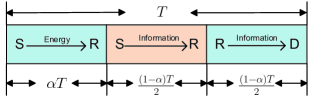
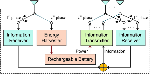
TSR secure system [29, 41] is included as a benchmark for performance comparisons. The secure communication based on TSR protocol consists of three phases, as shown in Fig. 3. One phase for energy harvesting and the other two phases for information transmission from source to destination with the help of a HD relay. Using TSR, the received SINR at the destination is expressed as

γdTSR=PsPr|𝐡d𝐰t|2|𝐡r1𝐰s|2PrN0|𝐡d𝐰t|2+PsN0|𝐡r1𝐰s|2+N02,superscriptsubscript𝛾𝑑𝑇𝑆𝑅subscript𝑃𝑠subscript𝑃𝑟superscriptsuperscriptsubscript𝐡𝑑subscript𝐰𝑡2superscriptsuperscriptsubscript𝐡𝑟1subscript𝐰𝑠2subscript𝑃𝑟subscript𝑁0superscriptsuperscriptsubscript𝐡𝑑subscript𝐰𝑡2subscript𝑃𝑠subscript𝑁0superscriptsuperscriptsubscript𝐡𝑟1subscript𝐰𝑠2superscriptsubscript𝑁02\gamma_{d}^{TSR}=\frac{P_{s}P_{r}|\mathbf{h}_{d}^{{\dagger}}\mathbf{w}_{t}|^{2}|\mathbf{h}_{r1}^{{\dagger}}\mathbf{w}_{s}|^{2}}{P_{r}N_{0}|\mathbf{h}_{d}^{{\dagger}}\mathbf{w}_{t}|^{2}+P_{s}N_{0}|\mathbf{h}_{r1}^{{\dagger}}\mathbf{w}_{s}|^{2}+N_{0}^{2}}, (33)

where Prsubscript𝑃𝑟P_{r} denotes transmit power at the relay, Pr=δ2α1αηPs|𝐡r1𝐰H|2subscript𝑃𝑟𝛿2𝛼1𝛼𝜂subscript𝑃𝑠superscriptsuperscriptsubscript𝐡𝑟1subscript𝐰𝐻2P_{r}=\delta\frac{2\alpha}{1-\alpha}\eta P_{s}|\mathbf{h}_{r1}^{{\dagger}}\mathbf{w}_{H}|^{2}, and δ𝛿\delta is defined as the power allocation ratio, 0δ10𝛿10\leq\delta\leq 1. Additionally, beamformers 𝐰ssubscript𝐰𝑠\mathbf{w}_{s} and 𝐰Hsubscript𝐰𝐻\mathbf{w}_{H} are both designed based on MRT, i.e., 𝐰s=𝐡r1𝐡r1subscript𝐰𝑠subscript𝐡𝑟1normsubscript𝐡𝑟1\mathbf{w}_{s}=\frac{\mathbf{h}_{r1}}{\|\mathbf{h}_{r1}\|} and 𝐰H=𝐡r1𝐡r1subscript𝐰𝐻subscript𝐡𝑟1normsubscript𝐡𝑟1\mathbf{w}_{H}=\frac{\mathbf{h}_{r1}}{\|\mathbf{h}_{r1}\|}.

The received SINR at the eavesdropper can be expressed as

γewcTSR=PsPr(|𝐡¯e𝐰t|+ϵ𝐰t)2|𝐡r1𝐰s|2PrN0(|𝐡¯e𝐰t|+ϵ𝐰t)2+PsN0|𝐡r1𝐰s|2+N02.superscriptsubscript𝛾𝑒𝑤𝑐𝑇𝑆𝑅subscript𝑃𝑠subscript𝑃𝑟superscriptsuperscriptsubscript¯𝐡𝑒subscript𝐰𝑡italic-ϵnormsubscript𝐰𝑡2superscriptsuperscriptsubscript𝐡𝑟1subscript𝐰𝑠2subscript𝑃𝑟subscript𝑁0superscriptsuperscriptsubscript¯𝐡𝑒subscript𝐰𝑡italic-ϵnormsubscript𝐰𝑡2subscript𝑃𝑠subscript𝑁0superscriptsuperscriptsubscript𝐡𝑟1subscript𝐰𝑠2superscriptsubscript𝑁02\gamma_{ewc}^{TSR}=\frac{P_{s}P_{r}(|\bar{\mathbf{h}}_{e}^{{\dagger}}\mathbf{w}_{t}|+\epsilon\|\mathbf{w}_{t}\|)^{2}|\mathbf{h}_{r1}^{{\dagger}}\mathbf{w}_{s}|^{2}}{P_{r}N_{0}(|\bar{\mathbf{h}}_{e}^{{\dagger}}\mathbf{w}_{t}|\!+\!\epsilon\|\mathbf{w}_{t}\|)^{2}\!+\!P_{s}N_{0}|\mathbf{h}_{r1}^{{\dagger}}\mathbf{w}_{s}|^{2}\!+\!N_{0}^{2}}.\\ (34)

Then, the WCSR for TSR secure systems is expressed as

Rwc=1α2[log2(1+γdTSR)log2(1+γewcTSR)]+.subscript𝑅𝑤𝑐1𝛼2superscriptdelimited-[]subscript21superscriptsubscript𝛾𝑑𝑇𝑆𝑅subscript21superscriptsubscript𝛾𝑒𝑤𝑐𝑇𝑆𝑅R_{wc}=\frac{1-\alpha}{2}[\log_{2}(1+\gamma_{d}^{TSR})-\log_{2}(1+\gamma_{ewc}^{TSR})]^{+}. (35)

Finally, the WCSR maximization problem is formulated as

(P3):maxα,δ,𝐰tRwc(α,δ,𝐰t):P3subscript𝛼𝛿subscript𝐰𝑡subscript𝑅𝑤𝑐𝛼𝛿subscript𝐰𝑡(\mathrm{P}3):~{}\max_{\alpha,\delta,\mathbf{w}_{t}}R_{wc}(\alpha,\delta,\mathbf{w}_{t})
s.t.{Pr=2δPsηα1α|𝐡r1𝐰H|2𝐰t2=10<α<10δ1.formulae-sequence𝑠𝑡casesmissing-subexpressionsubscript𝑃𝑟2𝛿subscript𝑃𝑠𝜂𝛼1𝛼superscriptsuperscriptsubscript𝐡𝑟1subscript𝐰𝐻2missing-subexpressionsuperscriptnormsubscript𝐰𝑡21missing-subexpression0𝛼1missing-subexpression0𝛿1s.t.\left\{\begin{array}[]{ll}&P_{r}=2\delta P_{s}\frac{\eta\alpha}{1-\alpha}|\mathbf{h}_{r1}^{{\dagger}}\mathbf{w}_{H}|^{2}\\ &\|\mathbf{w}_{t}\|^{2}=1\\ &0<\alpha<1\\ &0\leq\delta\leq 1\\ \end{array}\right.. (36)

It is obvious that the transmit beamformer 𝐰tsubscript𝐰𝑡\mathbf{w}_{t} and the power allocation ratio δ𝛿\delta as well as the TS coefficient α𝛼\alpha are coupled with each other, and the above problem is non-convex. To solve problem P3P3\mathrm{P}3 effectively, an iterative algorithm is summarized in Algorithm 2.

Algorithm 2 Iterative Algorithm for WCSR Optimization
1:  Initialize 𝐰s=𝐡r1𝐡r1subscript𝐰𝑠subscript𝐡𝑟1normsubscript𝐡𝑟1\mathbf{w}_{s}=\frac{\mathbf{h}_{r1}}{\|\mathbf{h}_{r1}\|}, 𝐰H=𝐡r1𝐡r1subscript𝐰𝐻subscript𝐡𝑟1normsubscript𝐡𝑟1\mathbf{w}_{H}=\frac{\mathbf{h}_{r1}}{\|\mathbf{h}_{r1}\|}, 𝐰t0superscriptsubscript𝐰𝑡0\mathbf{w}_{t}^{0}, α0superscript𝛼0\alpha^{0}, δ0superscript𝛿0\delta^{0}, ε𝜀\varepsilon, calculate Rwc(𝐰t0,α0,δ0)subscript𝑅𝑤𝑐superscriptsubscript𝐰𝑡0superscript𝛼0superscript𝛿0R_{wc}(\mathbf{w}_{t}^{0},\alpha^{0},\delta^{0}), and set n=0𝑛0n=0.
2:  repeat
3:     n=n+1𝑛𝑛1n=n+1
4:     For the fixed 𝐰tn1,αn1superscriptsubscript𝐰𝑡𝑛1superscript𝛼𝑛1\mathbf{w}_{t}^{n-1},\alpha^{n-1}, find δnsuperscript𝛿𝑛\delta^{n} using Lemma 1 proposed in [25].
5:     With δnsuperscript𝛿𝑛\delta^{n} and fixed αn1superscript𝛼𝑛1\alpha^{n-1}, calculate 𝐰tnsuperscriptsubscript𝐰𝑡𝑛\mathbf{w}_{t}^{n} using an approach similar to Section III-C.
6:     For the obtained δnsuperscript𝛿𝑛\delta^{n} and 𝐰tnsuperscriptsubscript𝐰𝑡𝑛\mathbf{w}_{t}^{n}, find the numerical solution of αnsuperscript𝛼𝑛\alpha^{n}, and calculate the secrecy rate Rwcn=Rwc(𝐰tn,αn,δn)superscriptsubscript𝑅𝑤𝑐𝑛subscript𝑅𝑤𝑐superscriptsubscript𝐰𝑡𝑛superscript𝛼𝑛superscript𝛿𝑛R_{wc}^{n}=R_{wc}(\mathbf{w}_{t}^{n},\alpha^{n},\delta^{n}).
7:  until |RwcnRwcn1|εsuperscriptsubscript𝑅𝑤𝑐𝑛superscriptsubscript𝑅𝑤𝑐𝑛1𝜀|R_{wc}^{n}-R_{wc}^{n-1}|\leq\varepsilon.
8:  return  (𝐰t,α,δ)=(𝐰tn,αn,δn)superscriptsubscript𝐰𝑡superscript𝛼superscript𝛿superscriptsubscript𝐰𝑡𝑛superscript𝛼𝑛superscript𝛿𝑛(\mathbf{w}_{t}^{\star},\alpha^{\star},\delta^{\star})=(\mathbf{w}_{t}^{n},\alpha^{n},\delta^{n})

V Simulation Results and Analysis

In this section, to validate the accuracy and effectiveness of the theoretical results developed in previous sections and evaluate WCSR performance of the wireless-powered relay system with S-ER, Monte Carlo simulations are done. All the simulation results are obtained by averaging over 104superscript10410^{4} independent trials. Unless otherwise specified, the source has five antennas (N=5𝑁5N=5), while the wireless-powered relay is equipped with four antennas, in which one antenna is used for information reception and energy harvesting, the other three antennas (M=3𝑀3M=3) used for both information transmission and reception. Without loss of generality, the source-relay distance and the relay-destination distance are both normalized to unit value [16], and the relay-eavesdropper distance dresubscript𝑑𝑟𝑒d_{re} is set to be 1.2drd1.2subscript𝑑𝑟𝑑1.2d_{rd}. All channels are assumed to be Rayleigh fading channels, and the mean value of each channel coefficient is associated with the distance between two nodes, i.e., σs2=dsrmsuperscriptsubscript𝜎𝑠2superscriptsubscript𝑑𝑠𝑟𝑚\sigma_{s}^{2}=d_{sr}^{-m}, σd2=drdmsuperscriptsubscript𝜎𝑑2superscriptsubscript𝑑𝑟𝑑𝑚\sigma_{d}^{2}=d_{rd}^{-m} and σe2=dremsuperscriptsubscript𝜎𝑒2superscriptsubscript𝑑𝑟𝑒𝑚\sigma_{e}^{2}=d_{re}^{-m}, in which the path loss exponent is set to be m=3𝑚3m=3. Besides, the mean value of LI channel coefficient 𝐟2superscriptnorm𝐟2\|\mathbf{f}\|^{2} is set to be λf=0.2subscript𝜆𝑓0.2\lambda_{f}=0.2, and the energy harvesting efficiency η=0.8𝜂0.8\eta=0.8.

V-A Uncertainty Region of ECSI

Refer to caption
Figure 4: WCSR versus the level of bounded uncertainty region of ECSI with different number of transmit antennas at the relay M=[2,3,4]𝑀234M=[2,3,4]. Additionally, the information leakage threshold is set to be γ0=106subscript𝛾0superscript106\gamma_{0}=10^{-6} bits/s/Hz.

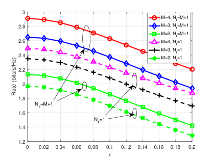
In a multi-antenna secure system, it is generally known that the secure beamformer design depends on the availability of CSI, especially the CSI of wiretap channels. If the source and the relay have only partial ECSI, there is a high probability in information leakage at the eavesdropper, finally leading to WCSR loss. Thus, in order to show how important it is to take imperfect ECSI into account for secure beamformer design, the WCSR performance versus the uncertainty region of ECSI is simulated. Results are shown in Fig. 4 and reveal that the increase of the level of the bounded eavesdropper channel uncertainty has destructive effect on the system performance. That is because this makes the secure beamformer design inefficient, leading to more information leakage to the eavesdropper, finally resulting in substantial WCSR degradation. In addition, results also show that compared with the scheme exploiting only one receive antenna for information reception (i.e., Nr=1subscript𝑁𝑟1N_{r}=1), the antenna reuse scheme (i.e., Nr=M+1subscript𝑁𝑟𝑀1N_{r}=M+1) achieves better WCSR performance. Intuitively, this is because more spatial degrees of freedom offered by reusing transmit antenna elements facilitate the information reception, enhance the received signal strength at relay. This results in an increase of received information rate at the destination, hence brings more WCSR gains. Moreover, putting more antennas at relay M=[2,3,4]𝑀234M=[2,3,4] would also offer more spatial degrees of freedom for information retransmission, and consequently improve the system WCSR. This is rather intuitive, since more antennas result in sharper information beams, which in turn yield higher secrecy performance.

V-B Power Allocation

Refer to caption
Figure 5: WCSR performance versus the ratio between the actual transmit power and the harvested power at the relay, i.e., δ=Pr/PH𝛿subscript𝑃𝑟subscript𝑃𝐻\delta=P_{r}/P_{H}, where PHsubscript𝑃𝐻P_{H} is the harvested power at the relay, PH=EHT/2subscript𝑃𝐻subscript𝐸𝐻𝑇2P_{H}=\frac{E_{H}}{T/2}.

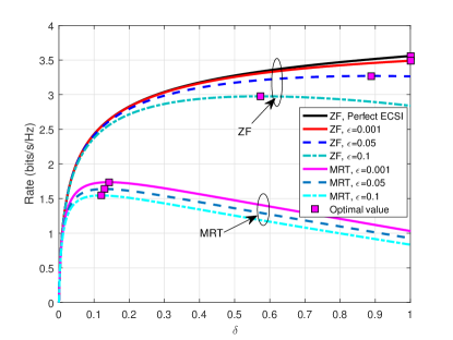
As analyzed in Section III, due to the presence of the eavesdropper node, using the harvested energy fully for information transmission has both constructive and destructive effects on the system performance. The increase of transmit power at the relay helps information retransmission, and consequently improves the received SINR at the destination. Meanwhile, increasing the transmit power at relay also enhances the information strength at eavesdropper, resulting in more information leakage. Hence, there exists an optimal power allocation strategy at relay maximizing the WCSR performance. To illustrate the effects of power allocation strategy on secrecy performance and demonstrate the accuracy of the derived optimal power allocation ratio solution in Proposition 1, the WCSR performance with different power allocation ratio is simulated. In doing so, we focus on a single transmission block with the following randomly generated channel coefficients: the source-to-relay channel 𝐡r1=[0.9693+0.4571i,1.4266+0.3548i,1.8713+0.8418i,0.72430.0702i,0.9796+0.3818i]Tsubscript𝐡𝑟1superscript0.96930.4571𝑖1.42660.3548𝑖1.87130.8418𝑖0.72430.0702𝑖0.97960.3818𝑖𝑇\mathbf{h}_{r1}=[-0.9693+0.4571i,-1.4266+0.3548i,-1.8713+0.8418i,0.7243-0.0702i,-0.9796+0.3818i]^{T}, and

𝐇r2=(0.5023+0.9428i1.02470.7866i0.2742+0.7717i0.05550.5340i1.59410.4515i0.19500.1796i0.7962+0.9197i1.08820.2271i0.37830.5202i1.01291.0110i1.14280.3521i0.06150.2866i0.0170+1.3779i1.24860.0870i0.19371.1660i).subscript𝐇𝑟2matrix0.50230.9428𝑖1.02470.7866𝑖0.27420.7717𝑖0.05550.5340𝑖1.59410.4515𝑖0.19500.1796𝑖0.79620.9197𝑖1.08820.2271𝑖0.37830.5202𝑖1.01291.0110𝑖1.14280.3521𝑖0.06150.2866𝑖0.01701.3779𝑖1.24860.0870𝑖0.19371.1660𝑖\displaystyle\!\mathbf{H}_{r2}\!\!=\!\!\!\begin{pmatrix}\!\!0.5023\!+\!0.9428i\!\!&\!\!1.0247\!-\!0.7866i\!\!&\!\!-0.2742\!+\!0.7717i\\ \!0.0555\!-\!0.5340i\!\!&\!\!-1.5941\!-\!0.4515i\!\!&\!\!-0.1950\!-\!0.1796i\\ \!-0.7962\!+\!0.9197i\!\!&\!\!-1.0882\!-\!0.2271i\!\!&\!\!0.3783\!-\!0.5202i\\ \!1.0129\!-\!1.0110i\!\!&\!\!-1.1428\!-\!0.3521i\!\!&\!\!-0.0615\!-\!0.2866i\\ \!0.0170\!+\!1.3779i\!\!&\!\!-1.2486\!-\!0.0870i\!\!&\!\!0.1937\!-\!1.1660i\\ \end{pmatrix}\!.\!

It is also assumed that the LI channel 𝐟=[0.6791+0.0424i,0.5303+0.1144i,0.55170.0069i]T𝐟superscript0.67910.0424𝑖0.53030.1144𝑖0.55170.0069𝑖𝑇\mathbf{f}=[-0.6791+0.0424i,0.5303+0.1144i,-0.5517-0.0069i]^{T}, while the relay-to-destination channel 𝐡d=[0.5039+0.3520i,0.42301.1293i,0.6480+1.6376i]Tsubscript𝐡𝑑superscript0.50390.3520𝑖0.42301.1293𝑖0.64801.6376𝑖𝑇\mathbf{h}_{d}=[-0.5039+0.3520i,0.4230-1.1293i,0.6480+1.6376i]^{T}, and the relay-to-eavesdropper channel 𝐡¯e=[0.64170.3991i,0.17650.9396i,0.52780.8778i]Tsubscript¯𝐡𝑒superscript0.64170.3991𝑖0.17650.9396𝑖0.52780.8778𝑖𝑇\bar{\mathbf{h}}_{e}=[0.6417-0.3991i,0.1765-0.9396i,-0.5278-0.8778i]^{T}. All the above channel coefficients are randomly generalized following their statistical properties. With different levels of bounded eavesdropper channel uncertainty ϵ=[0.001,0.05,0.1]italic-ϵ0.0010.050.1\epsilon=[0.001,0.05,0.1], the WCSR performance versus the ratio between the actual transmit power and the harvested power at the relay is included in Fig. 5. It is shown that the simulation results are highly coherent with the theoretical solutions obtained in Proposition 1, and there exists an optimal power allocation ratio maximizing WCSR. Moreover, results also verify that compared with MRT beamforming design method, i.e., 𝐰t=𝐡d𝐡dsuperscriptsubscript𝐰𝑡subscript𝐡𝑑normsubscript𝐡𝑑\mathbf{w}_{t}^{\star}=\frac{\mathbf{h}_{d}}{\|\mathbf{h}_{d}\|}, the proposed robust ZF beamforming method can considerably reduce the effects caused by the channel uncertainty on the system secrecy, and offers higher WCSR gain.

V-C Key Parameters

Refer to caption
Figure 6: WCSR performance versus the strength of LI for the proposed S-ER based secure system and traditional TSR secure system. The eavesdropper channel uncertainty region is set to be ϵ=[0.001,0.05]italic-ϵ0.0010.05\epsilon=[0.001,0.05].

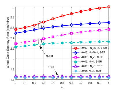
In a S-ER based wireless-powered secure relay system, the strength of LI channel determines how much amount of interference energy the relay can recycle and reuse for information retransmission. Therefore, it is a key parameter determining the superiority of the secrecy performance. Fig. 6 shows the WCSR performance of both S-ER based secure system and TSR system when the strength of LI channel is different. Contrary to traditional FD relaying systems, the LI does not interfere information transmission, but brings another energy resource at relay to support information relaying. Therefore, as shown in Fig. 6, increasing λfsubscript𝜆𝑓\lambda_{f} leads to an increase of WCSR performance of the proposed S-ER based secure systems. While, the secrecy rate remains a constant because there is no interference in TSR systems. Since a novel energy resource (LI energy) is introduced by the FD operation at the relay in S-ER based system, its secrecy performance is significantly boosted compared with TSR systems. Even setting λf=0subscript𝜆𝑓0\lambda_{f}=0, in S-ER based systems, more WCSR gain can be obtained through simultaneous information transmission and energy harvesting strategy than in TSR systems. Specifically, with fixed eavesdropper channel uncertainty ϵ=0.001italic-ϵ0.001\epsilon=0.001, the proposed S-ER based secure system achieves more than 38%80%percent38percent8038\%-80\% WCSR gain compared with TSR system for both Nr=M+1subscript𝑁𝑟𝑀1N_{r}=M+1 and Nr=1subscript𝑁𝑟1N_{r}=1. With more higher eavesdropper channel uncertainty ϵ=0.05italic-ϵ0.05\epsilon=0.05, the proposed S-ER based secure system can also offer 36%65%percent36percent6536\%-65\% rate gain. Moreover, since LI brings extra energy resource at relay instead of harmful interference for information transmission, the relay does not have to spend extra energy or other communication resources to suppress it. This makes it possible for S-ER based secure systems to benefit from significant secrecy performance improvement without no extra resource consumptions.

Refer to caption
Figure 7: WCSR performance versus energy harvesting efficiency for both S-ER based secure systems and TSR secure systems. The strength of LI channel is set to be λf=0.2subscript𝜆𝑓0.2\lambda_{f}=0.2.

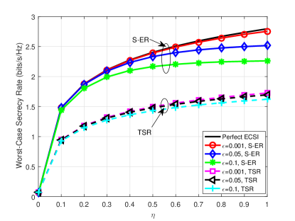
As illustrated in Fig. 6, the strength of LI channel and the energy conversion efficiency factor η𝜂\eta determine how much energy the relay can actually harvest from energy signals emitted by the source node and interference signals caused by LI channel. Higher energy conversion efficiency allows wireless-powered relay to harvest more energy from energy signals, which in turn enhances the received information rate at the destination, finally improves the WCSR performance substantially, as shown in Fig. 7. Nevertheless, as the harvested energy increased along with η𝜂\eta, it also leads to more serious information leakage, eventually results in the secrecy performance increasing slowly in high η𝜂\eta regime. Additionally, simulation results also show that the WCSR gap between the proposed S-ER based systems and TSR systems is more than 0.70.70.7 bits/s/Hz in high η𝜂\eta regime, which is about 40% rate gain. It indicates that with the introduced LI as extra energy resource for the wireless-powered relay node, the S-ER based system achieves much better WCSR performance than TSR systems.

Refer to caption
Figure 8: WCSR performance for different source-relay distance dsr=[0.5,1,1.5]subscript𝑑𝑠𝑟0.511.5d_{sr}=[0.5,1,1.5]. Without loss of generality, the strength of LI channel is set to be λf=0.2subscript𝜆𝑓0.2\lambda_{f}=0.2, and the energy harvesting efficiency is set to be η=0.8𝜂0.8\eta=0.8.

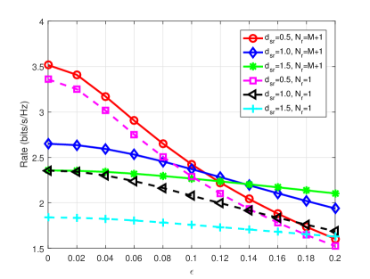
The location of relay can also impact on the received information rate at receivers (including both destination and eavesdropper nodes). Therefore, the relay layout is of great importance in the cooperative wireless-powered systems [16, 25]. In this part, the WCSR performance for different relay locations is also simulated and investigated, and results are included in Fig. 8. Results show that with the eavesdropper channel uncertainty, the wireless-powered relay located near to the source or the destination offers optimal secrecy performance. The reason is that the relay node is solely powered by the source. In low ϵitalic-ϵ\epsilon regime, when the relay is located near to the source, it can harvest more energy for information relaying and hence improves WCSR performance. While in high ϵitalic-ϵ\epsilon regime, excessive amount of energy harvested at relay will lead to serious information leakage, and results in high secrecy performance loss. Therefore, in this case, the relay located near the source does not bring more performance gain but serious performance loss. On the contrary, the wireless-powered relay approaching to the destination can obtain better WCSR performance. Since when the relay node located near the destination, the required relay power to achieve the information transmission from relay to destination is also reduced, the destination can still achieve better performance.

VI Conclusion

This work investigated robust secure beamforming design and relay power allocation of a wireless-powered relay system with imperfect ECSI. For efficient energy transfer and information relaying, a two-phase FD relaying protocol was investigated, in which the S-ER enabled relay recycles LI energy and utilizes the gathered energy for information relaying. Adopting the worst-case deterministic ECSI model, the WCSR optimization problem was formulated by jointly designing source and relay beamformers coupled with power allocation ratio. As the formulated problem is non-convex, an alternative method has been proposed to solve it more efficiently. Through converting the original optimization problem into three subproblems and solving them iteratively, the closed form solutions of the optimal source information beamformer, receive beamformer and transmit beamformer of the relay as well as optimal power allocation ratio were derived theoretically. Additionally, for comparison, the WCSR performance of TSR system has been included and analyzed. Intensive simulations have been done, and results have validated the effectiveness of the proposed iterative method and the accuracy of the derived variables. Results also have revealed that the proposed S-ER based secure system outperforms TSR system significantly. Moreover, it has been demonstrated that since the proposed antenna reuse scheme can capture more information, it boosts the WCSR performance substantially when compared with schemes exploiting only one receive antenna.

Appendix A Proof of Proposition 1

According to the definition of WCSR in (7), Rwc>0subscript𝑅𝑤𝑐0R_{wc}>0 is equivalent to γd>γewcsubscript𝛾𝑑subscript𝛾𝑒𝑤𝑐\gamma_{d}>\gamma_{ewc}, i.e., the received SINR at the destination is larger than that at the eavesdropper.

Based on the expressions of γdsubscript𝛾𝑑\gamma_{d} and γewcsubscript𝛾𝑒𝑤𝑐\gamma_{ewc} in equation (8) and (12), it is easy to know that both of them can be formulated in the form of g(y)=c1y/(c2y+c3)𝑔𝑦subscript𝑐1𝑦subscript𝑐2𝑦subscript𝑐3g(y)=c_{1}y/(c_{2}y+c_{3}), where y𝑦y denotes the channel condition, |𝐡d𝐰t|2superscriptsuperscriptsubscript𝐡𝑑subscript𝐰𝑡2|\mathbf{h}_{d}^{{\dagger}}\mathbf{w}_{t}|^{2} or (|𝐡¯e𝐰t|+ϵ𝐰t)2superscriptsuperscriptsubscript¯𝐡𝑒subscript𝐰𝑡italic-ϵnormsubscript𝐰𝑡2(|\bar{\mathbf{h}}_{e}^{{\dagger}}\mathbf{w}_{t}|+\epsilon\|\mathbf{w}_{t}\|)^{2}. It can be proved that g(y)𝑔𝑦g(y) is a monotonically increasing function of y𝑦y. Consequently, if and only if |𝐡d𝐰t|2superscriptsuperscriptsubscript𝐡𝑑subscript𝐰𝑡2|\mathbf{h}_{d}^{{\dagger}}\mathbf{w}_{t}|^{2} is larger than (|𝐡¯e𝐰t|+ϵ𝐰t)2superscriptsuperscriptsubscript¯𝐡𝑒subscript𝐰𝑡italic-ϵnormsubscript𝐰𝑡2(|\bar{\mathbf{h}}_{e}^{{\dagger}}\mathbf{w}_{t}|+\epsilon\|\mathbf{w}_{t}\|)^{2}, the received SINR at the destination is larger than the received SINR at the eavesdropper. The positive secrecy rate is achieved and the security of information transmission is guaranteed. Otherwise, the secrecy rate will be non-positive.

Appendix B Proof of Proposition 2

The secrecy rate is the function of power allocation ratio δ𝛿\delta. For analysis simplicity, introducing x,0x1𝑥0𝑥1x,0\leq x\leq 1, to substitute δ𝛿\delta, the rate can be formulated as a function f(x)𝑓𝑥f(x)

f(x)=12(log2(1+a1xa2x+1)log2(1+a3xa4x+1)),𝑓𝑥12subscript21subscript𝑎1𝑥subscript𝑎2𝑥1subscript21subscript𝑎3𝑥subscript𝑎4𝑥1f(x)=\frac{1}{2}\left(\log_{2}(1+\frac{a_{1}x}{a_{2}x+1})-\log_{2}(1+\frac{a_{3}x}{a_{4}x+1})\right), (37)

where parameters a1subscript𝑎1a_{1}, a2subscript𝑎2a_{2}, a3subscript𝑎3a_{3} and a4subscript𝑎4a_{4} are expressed as

a1=ηPs2|𝐡d𝐰t|2|𝐰r𝐇r𝐰s|2|𝐡r1𝐰H|2N0Ps|𝐰r𝐇r𝐰s2+N02,subscript𝑎1𝜂superscriptsubscript𝑃𝑠2superscriptsuperscriptsubscript𝐡𝑑subscript𝐰𝑡2superscriptsuperscriptsubscript𝐰𝑟superscriptsubscript𝐇𝑟subscript𝐰𝑠2superscriptsuperscriptsubscript𝐡𝑟1subscript𝐰𝐻2conditionalsubscript𝑁0subscript𝑃𝑠superscriptsubscript𝐰𝑟superscriptsubscript𝐇𝑟superscriptsubscript𝐰𝑠2superscriptsubscript𝑁02a_{1}=\frac{\eta P_{s}^{2}|\mathbf{h}_{d}^{{\dagger}}\mathbf{w}_{t}|^{2}|\mathbf{w}_{r}^{{\dagger}}\mathbf{H}_{r}^{{\dagger}}\mathbf{w}_{s}|^{2}|\mathbf{h}_{r1}^{{\dagger}}\mathbf{w}_{H}|^{2}}{N_{0}P_{s}|\mathbf{w}_{r}^{{\dagger}}\mathbf{H}_{r}^{{\dagger}}\mathbf{w}_{s}^{2}+N_{0}^{2}},\\
a2=ηPsN0|𝐡d𝐰t|2|𝐡r1𝐰H|2N0Ps|𝐰r𝐇r𝐰s|2+N02η|𝐟𝐰t|2,subscript𝑎2𝜂subscript𝑃𝑠subscript𝑁0superscriptsuperscriptsubscript𝐡𝑑subscript𝐰𝑡2superscriptsuperscriptsubscript𝐡𝑟1subscript𝐰𝐻2subscript𝑁0subscript𝑃𝑠superscriptsuperscriptsubscript𝐰𝑟superscriptsubscript𝐇𝑟subscript𝐰𝑠2superscriptsubscript𝑁02𝜂superscriptsuperscript𝐟subscript𝐰𝑡2a_{2}=\frac{\eta P_{s}N_{0}|\mathbf{h}_{d}^{{\dagger}}\mathbf{w}_{t}|^{2}|\mathbf{h}_{r1}^{{\dagger}}\mathbf{w}_{H}|^{2}}{N_{0}P_{s}|\mathbf{w}_{r}^{{\dagger}}\mathbf{H}_{r}^{{\dagger}}\mathbf{w}_{s}|^{2}+N_{0}^{2}}-\eta|\mathbf{f}^{{\dagger}}\mathbf{w}_{t}|^{2},\\
a3=ηPs2(|𝐡¯e𝐰t|+ϵ𝐰t)2|𝐰r𝐇r𝐰s|2|𝐡r1𝐰H|2N0Ps|𝐰r𝐇r𝐰s|2+N02,subscript𝑎3𝜂superscriptsubscript𝑃𝑠2superscriptsuperscriptsubscript¯𝐡𝑒subscript𝐰𝑡italic-ϵnormsubscript𝐰𝑡2superscriptsuperscriptsubscript𝐰𝑟superscriptsubscript𝐇𝑟subscript𝐰𝑠2superscriptsuperscriptsubscript𝐡𝑟1subscript𝐰𝐻2subscript𝑁0subscript𝑃𝑠superscriptsuperscriptsubscript𝐰𝑟superscriptsubscript𝐇𝑟subscript𝐰𝑠2superscriptsubscript𝑁02a_{3}=\frac{\eta P_{s}^{2}(|\bar{\mathbf{h}}_{e}^{{\dagger}}\mathbf{w}_{t}|+\epsilon\|\mathbf{w}_{t}\|)^{2}|\mathbf{w}_{r}^{{\dagger}}\mathbf{H}_{r}^{{\dagger}}\mathbf{w}_{s}|^{2}|\mathbf{h}_{r1}^{{\dagger}}\mathbf{w}_{H}|^{2}}{N_{0}P_{s}|\mathbf{w}_{r}^{{\dagger}}\mathbf{H}_{r}^{{\dagger}}\mathbf{w}_{s}|^{2}+N_{0}^{2}},\\
a4=ηPsN0(|𝐡¯e𝐰t|+ϵ𝐰t)2|𝐡r1𝐰H|2N0Ps|𝐰r𝐇r𝐰s|2+N02η|𝐟𝐰t|2.subscript𝑎4𝜂subscript𝑃𝑠subscript𝑁0superscriptsuperscriptsubscript¯𝐡𝑒subscript𝐰𝑡italic-ϵnormsubscript𝐰𝑡2superscriptsuperscriptsubscript𝐡𝑟1subscript𝐰𝐻2subscript𝑁0subscript𝑃𝑠superscriptsuperscriptsubscript𝐰𝑟superscriptsubscript𝐇𝑟subscript𝐰𝑠2superscriptsubscript𝑁02𝜂superscriptsuperscript𝐟subscript𝐰𝑡2a_{4}=\frac{\eta P_{s}N_{0}(|\bar{\mathbf{h}}_{e}^{{\dagger}}\mathbf{w}_{t}|+\epsilon\|\mathbf{w}_{t}\|)^{2}|\mathbf{h}_{r1}^{{\dagger}}\mathbf{w}_{H}|^{2}}{N_{0}P_{s}|\mathbf{w}_{r}^{{\dagger}}\mathbf{H}_{r}^{{\dagger}}\mathbf{w}_{s}|^{2}+N_{0}^{2}}-\eta|\mathbf{f}^{{\dagger}}\mathbf{w}_{t}|^{2}.\\

It is obvious that a1>0subscript𝑎10a_{1}>0, a3>0subscript𝑎30a_{3}>0. Moreover, under the positive secrecy rate constraint proved in Proposition 1, we have a1>a3subscript𝑎1subscript𝑎3a_{1}>a_{3}, a2>a4subscript𝑎2subscript𝑎4a_{2}>a_{4}.

The derivative of f(x)𝑓𝑥f(x) is expressed as

df(x)dx=1ln2((a1a42a22a3)+a1a3(a4a2))x2(1+a1x+a2x)(1+a2x)(1+a3x+a4x)(1+a4x)+1ln22(a1a4a2a3)x+a1a3(1+a1x+a2x)(1+a2x)(1+a3x+a4x)(1+a4x).𝑑𝑓𝑥𝑑𝑥12subscript𝑎1superscriptsubscript𝑎42superscriptsubscript𝑎22subscript𝑎3subscript𝑎1subscript𝑎3subscript𝑎4subscript𝑎2superscript𝑥21subscript𝑎1𝑥subscript𝑎2𝑥1subscript𝑎2𝑥1subscript𝑎3𝑥subscript𝑎4𝑥1subscript𝑎4𝑥122subscript𝑎1subscript𝑎4subscript𝑎2subscript𝑎3𝑥subscript𝑎1subscript𝑎31subscript𝑎1𝑥subscript𝑎2𝑥1subscript𝑎2𝑥1subscript𝑎3𝑥subscript𝑎4𝑥1subscript𝑎4𝑥\displaystyle\small\begin{split}\frac{df(x)}{dx}=&\frac{1}{\ln 2}\frac{\left((a_{1}a_{4}^{2}-a_{2}^{2}a_{3})+a_{1}a_{3}(a_{4}-a_{2})\right)x^{2}}{(1\!+\!a_{1}x\!+\!a_{2}x)(1\!+\!a_{2}x)(1\!+\!a_{3}x\!+\!a_{4}x)(1\!+\!a_{4}x)}\\ &\!+\!\frac{1}{\ln 2}\frac{2(a_{1}a_{4}\!-\!a_{2}a_{3})x+a_{1}-a_{3}}{(1\!+\!a_{1}x\!+\!a_{2}x)(1\!+\!a_{2}x)(1\!+\!a_{3}x\!+\!a_{4}x)(1\!+\!a_{4}x)}.\end{split}

As the denominator of df(x)/dx𝑑𝑓𝑥𝑑𝑥df(x)/dx is always positive for x0𝑥0x\geq 0, the sign of the numerator polynomial of df(x)/dx𝑑𝑓𝑥𝑑𝑥df(x)/dx

h(x)=((a1a42a22a3)+a1a3(a4a2))x2+2(a1a4a2a3)x+a1a3,𝑥subscript𝑎1superscriptsubscript𝑎42superscriptsubscript𝑎22subscript𝑎3subscript𝑎1subscript𝑎3subscript𝑎4subscript𝑎2superscript𝑥22subscript𝑎1subscript𝑎4subscript𝑎2subscript𝑎3𝑥subscript𝑎1subscript𝑎3\displaystyle\begin{split}h(x)=&\left((a_{1}a_{4}^{2}-a_{2}^{2}a_{3})+a_{1}a_{3}(a_{4}-a_{2})\right)x^{2}\\ &+2(a_{1}a_{4}-a_{2}a_{3})x+a_{1}-a_{3},\\ \end{split} (38)

determines the monotonicity and optimality of f(x)𝑓𝑥f(x). Defining A=(a1a42a22a3)+a1a3(a4a2)𝐴subscript𝑎1superscriptsubscript𝑎42superscriptsubscript𝑎22subscript𝑎3subscript𝑎1subscript𝑎3subscript𝑎4subscript𝑎2A=(a_{1}a_{4}^{2}-a_{2}^{2}a_{3})+a_{1}a_{3}(a_{4}-a_{2}), B=2(a1a4a2a3)𝐵2subscript𝑎1subscript𝑎4subscript𝑎2subscript𝑎3B=2(a_{1}a_{4}-a_{2}a_{3}), C=a1a3𝐶subscript𝑎1subscript𝑎3C=a_{1}-a_{3}, we have B<0𝐵0B<0, C>0𝐶0C>0, h(0)=C>00𝐶0h(0)=C>0 and Δ=4a1a3(a2a4)(a1+a2a3a4)>0Δ4subscript𝑎1subscript𝑎3subscript𝑎2subscript𝑎4subscript𝑎1subscript𝑎2subscript𝑎3subscript𝑎40\Delta=4a_{1}a_{3}(a_{2}-a_{4})(a_{1}+a_{2}-a_{3}-a_{4})>0. It means that there are two roots for h(x)=0𝑥0h(x)=0. In the following, the sign of h(x)𝑥h(x) is analyzed.

1) For A>0𝐴0A>0, i.e., η|𝐟𝐰t|2>Q𝜂superscriptsuperscript𝐟subscript𝐰𝑡2𝑄\eta|\mathbf{f}^{{\dagger}}\mathbf{w}_{t}|^{2}>Q. Based on Vieta theory, it is easy to prove that there are two positive roots for h(x)=0𝑥0h(x)=0, and one of them is larger than 111. Therefore, two cases of the sign of h(1)=(1η|𝐟𝐰t|2)2Q21superscript1𝜂superscriptsuperscript𝐟subscript𝐰𝑡22superscript𝑄2h(1)=\left(1-\eta|\mathbf{f}^{{\dagger}}\mathbf{w}_{t}|^{2}\right)^{2}-Q^{2} should be analyzed.

Case i) For h(1)010h(1)\geq 0, we have Q<η|𝐟𝐰t|21Q𝑄𝜂superscriptsuperscript𝐟subscript𝐰𝑡21𝑄Q<\eta|\mathbf{f}^{{\dagger}}\mathbf{w}_{t}|^{2}\leq 1-Q and Q<12𝑄12Q<\frac{1}{2}. In this case, both two roots are no less than x=1𝑥1x=1. So, the sign of h(x)𝑥h(x) is always positive in the interval 0x10𝑥10\leq x\leq 1. That is, the function f(x)𝑓𝑥f(x) is monotonically increasing with respect to 0x10𝑥10\leq x\leq 1, and the optimal solution is x=1superscript𝑥1x^{\star}=1.

Case ii) For h(1)<010h(1)<0, we have η|𝐟𝐰t|2>max(Q,1Q)𝜂superscriptsuperscript𝐟subscript𝐰𝑡2𝑄1𝑄\eta|\mathbf{f}^{{\dagger}}\mathbf{w}_{t}|^{2}>\max(Q,1-Q) and 0<Q<10𝑄10<Q<1. In this case, one root is larger than x=1𝑥1x=1 and the other one is less than x=1𝑥1x=1, i.e., the sign of h(x)𝑥h(x) is changed from positive to negative. Thus f(x)𝑓𝑥f(x) is concave, and the optimal solution equals to

x=1η|𝐟𝐰t|2+Qsuperscript𝑥1𝜂superscriptsuperscript𝐟subscript𝐰𝑡2𝑄x^{\star}=\frac{1}{\eta|\mathbf{f}^{{\dagger}}\mathbf{w}_{t}|^{2}+Q} (39)

2) For A0𝐴0A\leq 0, i.e., η|𝐟𝐰t|2Q𝜂superscriptsuperscript𝐟subscript𝐰𝑡2𝑄\eta|\mathbf{f}^{{\dagger}}\mathbf{w}_{t}|^{2}\leq Q. Based on Vieta theory, it is easy to prove that there are one positive root and one negative root for h(x)=0𝑥0h(x)=0, and the absolute value of the negative root is larger than the positive one, thus h(x)𝑥h(x) is monotonically decreasing in the interval 0x10𝑥10\leq x\leq 1.

Case i) h(1)010h(1)\geq 0, we have η|𝐟𝐰t|2min(Q,1Q)𝜂superscriptsuperscript𝐟subscript𝐰𝑡2𝑄1𝑄\eta|\mathbf{f}^{{\dagger}}\mathbf{w}_{t}|^{2}\leq\min(Q,1-Q) and 0<Q<10𝑄10<Q<1. Since h(0)>000h(0)>0, h(1)010h(1)\geq 0 and h(x)𝑥h(x) is monotonically decreasing, then we have h(x)0𝑥0h(x)\geq 0. Therefore, the function f(x)𝑓𝑥f(x) is monotonically increasing for 0x10𝑥10\leq x\leq 1, and the optimal solution is x=1superscript𝑥1x^{\star}=1.

Case ii) For h(1)=010h(1)=0, we have η|𝐟𝐰t|2=1Q𝜂superscriptsuperscript𝐟subscript𝐰𝑡21𝑄\eta|\mathbf{f}^{{\dagger}}\mathbf{w}_{t}|^{2}=1-Q and 12<Q<112𝑄1\frac{1}{2}<Q<1. In this case, with the condition h(0)>000h(0)>0, it is easy to prove that h(x)0𝑥0h(x)\geq 0 for 0x10𝑥10\leq x\leq 1, i.e., the function f(x)𝑓𝑥f(x) is monotonically increasing in 0x10𝑥10\leq x\leq 1, and the optimal solution is x=1superscript𝑥1x^{\star}=1.

Case iii) For h(1)<010h(1)<0, when A<0𝐴0A<0, we have 1Q<η|𝐟𝐰t|2<min(1,Q)1𝑄𝜂superscriptsuperscript𝐟subscript𝐰𝑡21𝑄1-Q<\eta|\mathbf{f}^{{\dagger}}\mathbf{w}_{t}|^{2}<\min(1,Q) and Q>12𝑄12Q>\frac{1}{2}, and when A=0𝐴0A=0, we have η|𝐟𝐰t|2=Q𝜂superscriptsuperscript𝐟subscript𝐰𝑡2𝑄\eta|\mathbf{f}^{{\dagger}}\mathbf{w}_{t}|^{2}=Q and 12<Q<112𝑄1\frac{1}{2}<Q<1. Specially, when A<0𝐴0A<0, the positive root is less than x=1𝑥1x=1, i.e., the sign of h(x)𝑥h(x) is changed from positive to negative. That is to say f(x)𝑓𝑥f(x) is concave, and the optimal solution is the same as in equation (39). Alternatively, when A=0𝐴0A=0, h(x)𝑥h(x) has only one positive root and less than x=1𝑥1x=1. Thus, similarly with A<0𝐴0A<0 case, f(x)𝑓𝑥f(x) is also concave, and the optimal solution is (39).

Consequently, combining case ii) in part 1) and case iii) in part 2), for constraints C1={0<Q<1,η|𝐟𝐰t|2>max(Q,1Q)}subscript𝐶10superscriptbra𝑄bra1𝜂superscript𝐟subscript𝐰𝑡2𝑄1𝑄C_{1}=\{0<Q<1,\eta|\mathbf{f}^{{\dagger}}\mathbf{w}_{t}|^{2}>\max(Q,1-Q)\}, or C2={Q>12,1Q<η|𝐟𝐰t|2<min(1,Q)}subscript𝐶2formulae-sequence𝑄121𝑄𝜂superscriptsuperscript𝐟subscript𝐰𝑡21𝑄C_{2}=\{Q>\frac{1}{2},1-Q<\eta|\mathbf{f}^{{\dagger}}\mathbf{w}_{t}|^{2}<\min(1,Q)\}, or C3={12<Q<1,η|𝐟𝐰t|2=Q}subscript𝐶312superscriptbra𝑄bra1𝜂superscript𝐟subscript𝐰𝑡2𝑄C_{3}=\{\frac{1}{2}<Q<1,\eta|\mathbf{f}^{{\dagger}}\mathbf{w}_{t}|^{2}=Q\}, the function f(x)𝑓𝑥f(x) is concave, and the optimal solution is derived as (39). Otherwise, the function f(x)𝑓𝑥f(x) is monotonically increasing in 0x10𝑥10\leq x\leq 1, and the optimal solution is x=1superscript𝑥1x^{\star}=1.

Appendix C Proof of Proposition 3

As the source information beamformer and the relay receive beamformer always appear together with the source-to-relay channel coefficients in a form of production, the WCSR performance with respect to |𝐰r𝐇r𝐰s|2superscriptsuperscriptsubscript𝐰𝑟superscriptsubscript𝐇𝑟subscript𝐰𝑠2|\mathbf{w}_{r}^{{\dagger}}\mathbf{H}_{r}^{{\dagger}}\mathbf{w}_{s}|^{2} is investigated. Since the solution of the optimal power allocation ratio δsuperscript𝛿\delta^{\star} in a piecewise expression, two cases should be analyzed.

1) For δ=1η|𝐟𝐰t|2+Qsuperscript𝛿1𝜂superscriptsuperscript𝐟subscript𝐰𝑡2𝑄\delta^{\star}=\frac{1}{\eta|\mathbf{f}^{{\dagger}}\mathbf{w}_{t}|^{2}+Q}, the received SINRs at the receive nodes (destination and eavesdropper) are expressed as

γd=Ps|𝐰r𝐇r𝐰s|2|𝐡d𝐰t|N0|𝐡d𝐰t|+(|𝐡¯e𝐰t|+ϵ𝐰t)N0Ps|𝐰r𝐇r𝐰s|2+N02,subscript𝛾𝑑subscript𝑃𝑠superscriptsuperscriptsubscript𝐰𝑟superscriptsubscript𝐇𝑟subscript𝐰𝑠2superscriptsubscript𝐡𝑑subscript𝐰𝑡subscript𝑁0superscriptsubscript𝐡𝑑subscript𝐰𝑡superscriptsubscript¯𝐡𝑒subscript𝐰𝑡italic-ϵnormsubscript𝐰𝑡subscript𝑁0subscript𝑃𝑠superscriptsuperscriptsubscript𝐰𝑟superscriptsubscript𝐇𝑟subscript𝐰𝑠2superscriptsubscript𝑁02\small\gamma_{d}=\frac{P_{s}|\mathbf{w}_{r}^{{\dagger}}\mathbf{H}_{r}^{{\dagger}}\mathbf{w}_{s}|^{2}|\mathbf{h}_{d}^{{\dagger}}\mathbf{w}_{t}|}{N_{0}|\mathbf{h}_{d}^{{\dagger}}\mathbf{w}_{t}|\!\!+\!\!(|\bar{\mathbf{h}}_{e}^{{\dagger}}\mathbf{w}_{t}|\!\!+\!\!\epsilon\|\mathbf{w}_{t}\|)\sqrt{N_{0}P_{s}|\mathbf{w}_{r}^{{\dagger}}\mathbf{H}_{r}^{{\dagger}}\mathbf{w}_{s}|^{2}\!+\!N_{0}^{2}}},
γewc=Ps|𝐰r𝐇r𝐰s|2(|𝐡¯e𝐰t|+ϵ𝐰t)N0(|𝐡¯e𝐰t|+ϵ𝐰t)+|𝐡d𝐰t|N0Ps|𝐰r𝐇r𝐰s|2+N02.subscript𝛾𝑒𝑤𝑐subscript𝑃𝑠superscriptsuperscriptsubscript𝐰𝑟superscriptsubscript𝐇𝑟subscript𝐰𝑠2superscriptsubscript¯𝐡𝑒subscript𝐰𝑡italic-ϵnormsubscript𝐰𝑡subscript𝑁0superscriptsubscript¯𝐡𝑒subscript𝐰𝑡italic-ϵnormsubscript𝐰𝑡superscriptsubscript𝐡𝑑subscript𝐰𝑡subscript𝑁0subscript𝑃𝑠superscriptsuperscriptsubscript𝐰𝑟superscriptsubscript𝐇𝑟subscript𝐰𝑠2superscriptsubscript𝑁02\small\gamma_{ewc}=\frac{P_{s}|\mathbf{w}_{r}^{{\dagger}}\mathbf{H}_{r}^{{\dagger}}\mathbf{w}_{s}|^{2}(|\bar{\mathbf{h}}_{e}^{{\dagger}}\mathbf{w}_{t}|+\epsilon\|\mathbf{w}_{t}\|)}{N_{0}(|\bar{\mathbf{h}}_{e}^{{\dagger}}\mathbf{w}_{t}|\!\!+\!\!\epsilon\|\mathbf{w}_{t}\|)\!\!+\!\!|\mathbf{h}_{d}^{{\dagger}}\mathbf{w}_{t}|\sqrt{\!N_{0}P_{s}|\mathbf{w}_{r}^{{\dagger}}\mathbf{H}_{r}^{{\dagger}}\mathbf{w}_{s}|^{2}\!\!+\!\!N_{0}^{2}}}.

With the definition of x=|𝐰r𝐇r𝐰s|2𝑥superscriptsuperscriptsubscript𝐰𝑟superscriptsubscript𝐇𝑟subscript𝐰𝑠2x=|\mathbf{w}_{r}^{{\dagger}}\mathbf{H}_{r}^{{\dagger}}\mathbf{w}_{s}|^{2}, and g(x)=Psx+N0𝑔𝑥subscript𝑃𝑠𝑥subscript𝑁0g(x)=\sqrt{P_{s}x+N_{0}}, the WCSR can be formed as a function of x𝑥x

f(x)=log2(a1g(x)+ca2a2g(x)+ca1),𝑓𝑥subscript2subscript𝑎1𝑔𝑥𝑐subscript𝑎2subscript𝑎2𝑔𝑥𝑐subscript𝑎1f(x)=\log_{2}\left(\frac{a_{1}g(x)+ca_{2}}{a_{2}g(x)+ca_{1}}\right), (40)

where c=N0𝑐subscript𝑁0c=\sqrt{N_{0}}, a1=|𝐡d𝐰t|subscript𝑎1superscriptsubscript𝐡𝑑subscript𝐰𝑡a_{1}=|\mathbf{h}_{d}^{{\dagger}}\mathbf{w}_{t}|, a2=|𝐡¯e𝐰t|+ϵ𝐰tsubscript𝑎2superscriptsubscript¯𝐡𝑒subscript𝐰𝑡italic-ϵnormsubscript𝐰𝑡a_{2}=|\bar{\mathbf{h}}_{e}^{{\dagger}}\mathbf{w}_{t}|+\epsilon\|\mathbf{w}_{t}\|. The derivative function is expressed as

df(x)dx=1ln2ca2(a1a2)(a1g(x)+ca2)(a2g(x)+ca1)dg(x)dx.𝑑𝑓𝑥𝑑𝑥12𝑐subscript𝑎2subscript𝑎1subscript𝑎2subscript𝑎1𝑔𝑥𝑐subscript𝑎2subscript𝑎2𝑔𝑥𝑐subscript𝑎1𝑑𝑔𝑥𝑑𝑥\frac{df(x)}{dx}=\frac{1}{\ln 2}\frac{ca_{2}(a_{1}-a_{2})}{(a_{1}g(x)+ca_{2})(a_{2}g(x)+ca_{1})}\frac{dg(x)}{dx}. (41)

As the denominator of (41) is always positive for x0𝑥0x\geq 0, the sign of df(x)/dx𝑑𝑓𝑥𝑑𝑥df(x)/dx is determined by the sign of its numerator. It is obvious that g(x)𝑔𝑥g(x) is an increasing function of x𝑥x, then we have the sign of its derivative function is positive, dg(x)/dx>0𝑑𝑔𝑥𝑑𝑥0dg(x)/dx>0. Additionally, under the positive WCSR constraint, a1>a2subscript𝑎1subscript𝑎2a_{1}>a_{2} always holds. Therefore, df(x)/dx𝑑𝑓𝑥𝑑𝑥df(x)/dx is always greater than zero, and f(x)𝑓𝑥f(x) is a monotonically increasing function of x0𝑥0x\geq 0.

2) For δ=1superscript𝛿1\delta^{\star}=1, the WCSR can be formed as the following function

h(x)=12log2(b1xb2x+1)12log2(b3xb4x+1).𝑥12subscript2subscript𝑏1𝑥subscript𝑏2𝑥112subscript2subscript𝑏3𝑥subscript𝑏4𝑥1h(x)=\frac{1}{2}\log_{2}\left(\frac{b_{1}x}{b_{2}x+1}\right)-\frac{1}{2}\log_{2}\left(\frac{b_{3}x}{b_{4}x+1}\right). (42)

On the basis of Lemma 1 proposed in [25], it is easily proved that h(x)𝑥h(x) is also an increasing function of x𝑥x.

Consequently, for any value of power allocation ratio δsuperscript𝛿\delta^{\star}, the WCSR is a monotonically increasing function of |𝐰r𝐇r𝐰s|2superscriptsuperscriptsubscript𝐰𝑟superscriptsubscript𝐇𝑟subscript𝐰𝑠2|\mathbf{w}_{r}^{{\dagger}}\mathbf{H}_{r}^{{\dagger}}\mathbf{w}_{s}|^{2}, and only if the maximum value of |𝐰r𝐇r𝐰s|2superscriptsuperscriptsubscript𝐰𝑟superscriptsubscript𝐇𝑟subscript𝐰𝑠2|\mathbf{w}_{r}^{{\dagger}}\mathbf{H}_{r}^{{\dagger}}\mathbf{w}_{s}|^{2} is achieved, the WCSR performance can be maximized.

References

  • [1] Y. Liu, H. H. Chen, and L. Wang, “Physical layer security for next generation wireless networks: Theories, technologies, and challenges,” IEEE Commun. Surveys Tuts., vol. 19, no. 1, pp. 347–376, Firstquarter 2017.
  • [2] A. D. Wyner, “The wire-tap channel,” Bell. Syst. Tech. J., vol. 54, pp. 1355–1387, Oct. 1975.
  • [3] J. Chen, R. Zhang, L. Song, Z. Han, and B. Jiao, “Joint relay and jammer selection for secure two-way relay networks,” IEEE Trans. Inf. Forensics Security, vol. 7, no. 1, pp. 310–320, Feb. 2012.
  • [4] Y. Ju, H. M. Wang, T. X. Zheng, and Q. Yin, “Secure transmissions in millimeter wave systems,” IEEE Trans. Commun., vol. 65, no. 5, pp. 2114–2127, May 2017.
  • [5] H. M. Wang, K. W. Huang, Q. Yang, and Z. Han, “Joint source-relay secure precoding for MIMO relay networks with direct links,” IEEE Trans. Commun., vol. 65, no. 7, pp. 2781–2793, Jul. 2017.
  • [6] L. Dong, Z. Han, A. P. Petropulu, and H. V. Poor, “Improving wireless physical layer security via cooperating relays,” IEEE Trans. Signal Process., vol. 58, no. 3, pp. 1875–1888, Mar. 2010.
  • [7] J. Qiao, H. Zhang, D. Yuan, and F. Zhao, “Rate optimization under amplify-and-forward based cooperation with single eavesdropper,” in Proc. IEEE APCC, Bali, Indonesia, Aug. 2013, pp. 1–5.
  • [8] X. Jiang, H. Lin, C. Zhong, X. Chen, and Z. Zhang, “Proactive eavesdropping in relaying systems,” IEEE Signal Process. Lett., vol. 24, no. 6, pp. 917–921, Jun. 2017.
  • [9] G. Chen, Y. Gong, P. Xiao, and J. A. Chambers, “Physical layer network security in the full-duplex relay system,” IEEE Trans. Inf. Forensics Security, vol. 10, no. 3, pp. 574–583, Mar. 2015.
  • [10] J. Qiao, H. Zhang, D. Wu, and D. Yuan, “Secrecy rate analysis for jamming assisted relay communications systems,” in Proc. IEEE ICASSP, Brisbane, Australia, Apr. 2015, pp. 3143–3147.
  • [11] J. H. Lee, “Full-duplex relay for enhancing physical layer security in multi-hop relaying systems,” IEEE Commun. Lett., vol. 19, no. 4, pp. 525–528, Apr. 2015.
  • [12] L. J. Rodriguez, N. H. Tran, T. Q. Duong, T. Le-Ngoc, M. Elkashlan, and S. Shetty, “Physical layer security in wireless cooperative relay networks: State of the art and beyond,” IEEE Commun. Mag., vol. 53, no. 12, pp. 32–39, Dec. 2015.
  • [13] IMT-2020 Promotion Group, “5G wireless technology architecture white paper,” 2015.
  • [14] R. Zhang and C. K. Ho, “MIMO broadcasting for simultaneous wireless information and power transfer,” IEEE Trans. Wireless Commun., vol. 12, no. 5, pp. 1989–2001, May 2013.
  • [15] X. Zhou, R. Zhang, and C. K. Ho, “Wireless information and power transfer: Architecture design and rate-energy tradeoff,” IEEE Trans. Commun., vol. 61, no. 11, pp. 4754–4767, Nov. 2013.
  • [16] C. Zhong, H. A. Suraweera, G. Zheng, I. Krikidis, and Z. Zhang, “Wireless information and power transfer with full duplex relaying,” IEEE Trans. Commun., vol. 62, no. 10, pp. 3447–3461, Oct. 2014.
  • [17] H. Xing, K. K. Wong, and A. Nallanathan, “Secure wireless energy harvesting-enabled AF-relaying SWIPT networks,” in Proc. IEEE ICC, London, UK, Jun. 2015, pp. 2307–2312.
  • [18] X. Chen, J. Chen, and T. Liu, “Secure transmission in wireless powered massive MIMO relaying systems: Performance analysis and optimization,” IEEE Trans. Veh. Technol., vol. 65, no. 10, pp. 8025–8035, Oct. 2016.
  • [19] X. Wang, Z. Zhang, and K. Long, “Secure beamforming for multiple-antenna amplify-and-forward relay networks,” IEEE Trans. Signal Process., vol. 64, no. 6, pp. 1477–1492, Mar. 2016.
  • [20] S. S. Kalamkar and A. Banerjee, “Secure communication via a wireless energy harvesting untrusted relay,” IEEE Trans. Veh. Technol., vol. 66, no. 3, pp. 2199–2213, Mar. 2017.
  • [21] W. Liu, X. Zhou, S. Durrani, and P. Popovski, “Secure communication with a wireless-powered friendly jammer,” IEEE Trans. Wireless Commun., vol. 15, no. 1, pp. 401–415, Jan. 2016.
  • [22] M. Liu and Y. Liu, “Power allocation for secure SWIPT systems with wireless-powered cooperative jamming,” IEEE Commun. Lett., vol. 21, no. 6, pp. 1353–1356, Jun. 2017.
  • [23] J. Moon, H. Lee, C. Song, and I. Lee, “Secrecy outage minimization for wireless powered communication networks with an energy harvesting jammer,” in Proc. IEEE GLOBECOM, Washington, DC, USA, Dec. 2016, pp. 1–5.
  • [24] Y. Bi and H. Chen, “Accumulate and jam: Towards secure communication via a wireless-powered full-duplex jammer,” IEEE J. Sel. Topics Signal Process., vol. 10, no. 8, pp. 1538–1550, Dec. 2016.
  • [25] J. Qiao, H. Zhang, X. Zhou, and D. Yuan, “Joint beamforming and time switching design for secrecy rate maximization in wireless-powered FD relay systems,” IEEE Trans. Veh. Technol., vol. PP, no. 99, pp. 1–1, 2017.
  • [26] Z. Mobini, M. Mohammadi, and C. Tellambura, “Security enhancement of wireless networks with wireless-powered full-duplex relay and friendly jammer nodes,” in Proc. IEEE ICC, Paris, France, May 2017, pp. 1329–1334.
  • [27] D. Bharadia, E. McMilin, and S. Katti, “Full duplex radios,” in Proc. ACM SIGCOMM, Hong Kong, China, Aug. 2013, pp. 375–386.
  • [28] A. Sabharwal, P. Schniter, D. Guo, D. W. Bliss, S. Rangarajan, and R. Wichman, “In-band full-duplex wireless: Challenges and opportunities,” IEEE J. Sel. Areas Commun., vol. 32, no. 9, pp. 1637–1652, Sep. 2014.
  • [29] Y. Zeng and R. Zhang, “Full-duplex wireless-powered relay with self-energy recycling,” IEEE Wireless Commun. Lett., vol. 4, no. 2, pp. 201–204, Apr. 2015.
  • [30] H. Kim, J. Kang, S. Jeong, K. E. Lee, and J. Kang, “Secure beamforming and self-energy recycling with full-duplex wireless-powered relay,” in Proc. IEEE CCNC, Las Vegas, NV, USA, Jan. 2016, pp. 662–667.
  • [31] A. E. Shafie and N. Al-Dhahir, “Secure communications in the presence of a buffer-aided wireless-powered relay with self-energy recycling,” IEEE Wireless Commun. Lett., vol. 5, no. 1, pp. 32–35, Feb. 2016.
  • [32] W. Wu, B. Wang, Z. Deng, and H. Zhang, “Secure beamforming for full-duplex wireless powered communication systems with self-energy recycling,” IEEE Wireless Commun. Lett., vol. 6, no. 2, pp. 146–149, Apr. 2017.
  • [33] J. Huang and A. L. Swindlehurst, “Robust secure transmission in MISO channels based on worst-case optimization,” IEEE Trans. Signal Process., vol. 60, no. 4, pp. 1696–1707, Apr. 2012.
  • [34] J. Wang and D. P. Palomar, “Worst-case robust MIMO transmission with imperfect channel knowledge,” IEEE Trans. Signal Process., vol. 57, no. 8, pp. 3086–3100, Aug. 2009.
  • [35] X. Chen, D. W. K. Ng, W. H. Gerstacker, and H. H. Chen, “A survey on multiple-antenna techniques for physical layer security,” IEEE Commun. Surveys Tuts., vol. 19, no. 2, pp. 1027–1053, Secondquarter 2017.
  • [36] I. Krikidis, H. A. Suraweera, P. J. Smith, and C. Yuen, “Full-duplex relay selection for amplify-and-forward cooperative networks,” IEEE Trans. Wireless Commun., vol. 11, no. 12, pp. 4381–4393, Dec. 2012.
  • [37] W. Mou, Y. Cai, W. Yang, W. Yang, X. Xu, and J. Hu, “Exploiting full duplex techniques for secure communication in SWIPT system,” in Proc. IEEE WCSP, Nanjing, China, Oct. 2015, pp. 1–6.
  • [38] A. Khisti and G. W. Wornell, “Secure transmission with multiple antennas I: The MISOME wiretap channel,” IEEE Trans. Inf. Theory, vol. 56, no. 7, pp. 3088–3104, Jul. 2010.
  • [39] X. Wang, K. Wang, and X. D. Zhang, “Secure relay beamforming with imperfect channel side information,” IEEE Trans. Veh. Technol., vol. 62, no. 5, pp. 2140–2155, Jun. 2013.
  • [40] J. Li and A. P. Petropulu, “Explicit solution of worst-case secrecy rate for MISO wiretap channels with spherical uncertainty,” IEEE Trans. Signal Process., vol. 60, no. 7, pp. 3892–3895, Jul. 2012.
  • [41] A. A. Nasir, X. Zhou, S. Durrani, and R. A. Kennedy, “Relaying protocols for wireless energy harvesting and information processing,” IEEE Trans. Wireless Commun., vol. 12, no. 7, pp. 3622–3636, Jul. 2013.