Effective Optimization Criteria and Relay Selection Algorithms for Physical-Layer Security in Multiple-Antenna Relay Networks
Abstract
Physical-layer security for wireless networks has become an
effective approach and recently drawn significant attention in the
literature. In particular, the deployment and allocation of
resources such as relays to assist the transmission have gained
significant interest due to their ability to improve the secrecy
rate of wireless networks. In this work, we examine relay selection
criteria with arbitrary knowledge of the channels of the users and
the eavesdroppers. We present alternative optimization criteria
based on the signal-to-interference and the secrecy rate criteria
that can be used for resource allocation and that do not require
knowledge of the channels of the eavesdroppers and the interference.
We then develop effective relay selection algorithms that can
achieve a high secrecy rate performance without the need for the
knowledge of the channels of the eavesdroppers and the interference.
Simulation results show that the proposed criteria and algorithms
achieve excellent performance.
Index Terms:
Physical-layer security, secrecy rate optimization, relay selection, linear algebra techniques.I Introduction
In the era of modern wireless communications, transmission security is facing great challenges due to the nature of wireless broadcasting. To achieve transmission security in wireless links, physical-layer security has been proposed by Shannon [1] and investigated under various wireless networks [4, 5, 6]. In order to measure the security of wireless networks, the secrecy rate (SR) has been defined as the difference between two mutual information terms associated with the channels of the legitimate users and the eavesdroppers, respectively. In [6, 7], the secrecy capacity of multi-input multi-output (MIMO) systems [2, 3] is shown to be equivalent to the maximum achievable SR. More specifically, the secrecy capacity for a particular wire-tap Gaussian MIMO channel is determined by an achievable scheme and the secrecy capacity region is established for the most general case with an arbitrary number of users. Furthermore, SR optimization is performed in the presence of a cooperative jammer.
Relay selection schemes are investigated in various scenarios such as multiuser relay networks, cooperative relay systems and cognitive relay networks. Relay selection methods are often considered with the impact of co-channel interference [3, 15, 16, 17, 18, 19, 41, 42], [20, 21, 22, 23, 24, 25, 26, 27, 28, 29, 70, 31, 32, 33, 35, 36, 37, 38, 39, 40], [43, 44, 31, 45, 46, 47, 48, 49, 50, 12, 51, 52, 53], [54, 55, 56, 57, 58, 75, 59, 60, 61, 62, 63, 64, 65], [66, 67, 68, 69, 70, 71, 72, 73, 74, 76, 77] ,[78, 79]. The performance in terms of secrecy rate can be significantly affected by the relay selection criterion adopted. Existing relay selection algorithms depend on the knowledge of the channels between the source to the relays and the relays to the users [10]. Taking the channels from the source to the eavesdroppers into account, a relay selection approach denoted max-ratio criterion has been proposed in [13] based on knowledge of the channels to both legitimate users and eavesdroppers. In prior work, the assumption of knowledge of the channels to the eavesdroppers has been adopted even though it is impractical. Studies have considered the max-ratio relay selection policy, which employs the signal-to-interference-plus-noise ratio (SINR) as the relay selection criterion and requires the knowledge of the interference between users and the channels to the eavesdroppers.
In this work, we examine the SR performance of multiple-relay selection algorithms based on the SINR and the SR criteria, which require the knowledge of the interference and the channels to the eavesdroppers in multiuser multiple-antenna relay networks. We present alternative optimization criteria based on the SINR and the SR criteria that can be used for resource allocation. We then develop novel effective relay selection algorithms based on the SINR and SR criteria that do not require knowledge of the channels of the eavesdroppers and interference by exploiting linear algebra properties and a simplification of the expressions. We also analyze the computational cost required by the proposed criteria for relay selection and their implication on the improvement of the secrecy rate of multiuser multiple-antenna relay networks. The SR performance of the proposed relaying criteria and relay algorithms is shown via simulations to approach that of techniques with full knowledge of the interference and the channels to the eavesdroppers.
In summary, the main contributions of this work are:
-
•
Optimization criteria based on the SINR and the SR criteria that can be used for resource allocation without the need for the knowledge of the interference and the channels to the eavesdroppers.
-
•
Effective relay selection algorithms based on the SINR and SR criteria, which do not need the knowledge of the interference and the channels to the eavesdroppers.
-
•
Analysis of the computational cost and the impact of the proposed criteria and algorithms on the secrecy rate.
-
•
A simulation study of the proposed criteria and relay selection algorithms in several scenarios of interest in multiuser multiple-antenna relay networks.
This paper is organized as follows. In Section II, the system model is introduced. The relay selection criteria are introduced in Section III, whereas the proposed algorithms are developed in Section IV. The simulations are presented and discussed in Section V. The conclusions are given in Section VI.
Notation: Bold uppercase letters denote matrices with size and bold lowercase letters denote column vectors with length . Conjugate, transpose, and conjugate transpose are represented by , and , respectively; is the identity matrix of size ; denotes a diagonal matrix with the elements of the vector along its diagonal; represents complex Gaussian random variables with independent and identically distributed () entries with zero mean and variance equal to . denotes the base-2 logarithm of the argument.
II System Model

A description of the downlink multiuser multiple-antenna relay network considered in this work is illustrated in Fig. 1, where the system employs two time slots to transmit the data from the source node to the users. Each relay and each user are equipped with and antennas, respectively. We consider a source node, which transmits to relays. To transmit the signal simultaneously to users, the total number of transmit antennas should be limited according to . For convenience, we assume that the number of the active antennas used for transmitting user signals is and . At the same time, in order to receive the signals with a set of relays, antennas at relays are employed. In the second time slot, the relays will forward the signals to users. During the transmission from the source to the users, there are eavesdroppers, which attempt to decode the signals. Each eavesdropper is equipped with antennas.
In this system, we assume that the eavesdroppers do not jam the transmission and the data transmitted to each user, relay, jammer and eavesdropper experience a flat-fading multiple-antenna channel. The source node has knowledge of the channels from the source to the relays as well as from the relays to the users. The quantities and denote the channel matrices of the th relay and the th eavesdropper, respectively. If we assume contains sets of -combinations of the total relay set then the task of relay selection is to choose the set of relays that satisfies a chosen criterion. Given the set of selected relays expressed as , the channel from the transmitter to the relays and the eavesdroppers can be obtained as and . The matrix represents the channel between the th relay and the th user. The channels from the selected relays to the th user can be described by
| (1) |
where and represents the th selected relay with a chosen relay selection criterion. In the following section we will further discuss various relay selection criteria, where is the total number of selected relays [80, 81, 82, 83, 84, 85, 86, 87, 101, 89, 90, 91, 92, 93, 94, 95, 96, 97, 98, 99, 100, 101, 102, 103, 104, 105, 106, 107, 108, 112, 110, 111, 112, 113, 114, 115, 116, 117, 118, 119, 120, 121, 122, 123, 124, 125, 126, 127, 128, 129, 130, 131].
In Phase I, the signal is transmitted from the source to the relays. If a precoder matrix is applied, when the relay is selected, the received signal in all relays can be expressed as
| (2) |
where is the noise vector that is assumed to be Gaussian. If the interference for relay is described by , then the received signal at relay is given by
| (3) |
In Phase II, the signal at the relay nodes is given by .
The received signal at user from the selected set of relays is described by
| (4) |
where represents the channel from the selected set of relays to user and is the noise vector at user .
III Problem Statement and Relay Selection Criteria
In this section, we state the relay selection problem and present a generic multiple-relay selection algorithm, which relies on exhaustive searches and can be employed with arbitrary criteria. We then review several relay selection criteria that are available in the literature for the system under consideration.
III-A Relay Selection Problem
In the presence of multiple relay nodes, relay selection is performed before transmission to the relays. In a half-duplex system, we use to represent a metric obtained with the information from the source to the relays and as another metric calculated with information from the relays to the users. Therefore, the relay selection criterion depends on and and can be expressed as
| (5) |
III-B Max-ratio criterion
Conventional relay selection is based on the full channel information between the source to the relays and the relays to the users. A max-link relay selection is developed based on the max-min relay selection for decode-and-forward (DF) relay systems [Krikidis]. With the consideration of the eavesdropper, a max-ratio selection [13] in a single-antenna scenario is given by
| (6) |
where
| (7) |
and
| (8) |
Furthermore, in the scenario with only statistical distribution of the CSI to the eavesdroppers, the parameter of channel coefficient in (7) and (8) are replaced by statistical values.
III-C SINR criterion
Based on the max-ratio criterion, when we consider a multiuser MIMO system, the interference is taken into account in the relay selection criterion. According to (3), the SINR criterion can be expressed similarly as
| (9) |
where is the average value of SINR over relay set . The SINR of the selected relay node can be obtained by
| (10) |
in (10), represents the th stream for the th relay. is the correlation matrix of the received signal for node and represents the sum of the correlation matrix of the interference and correlation matrix of the noise. Similarly, is the average value of SINR with relay set to users. The SINR of user can then be calculated by
| (11) |
where and is the th stream for user .
III-D Secrecy rate criterion
In a multi-user MIMO system, the secrecy-rate criterion for a multi-user MIMO system considering interferences [spencercapacity] is given by
| (12) |
where is given as
| (13) |
and
| (14) |
In (12), the criterion is based on the secrecy rate related to destination and in a relay system the destination can be relays as well as users.
IV Proposed relay selection algorithms
In the aforementioned relay selection criteria, the channels of the source to eavesdroppers as well as the interference are assumed to be available at the transmitter. However, this assumption is hard to achieve in wireless transmissions [Xiang]. To obviate this need, we propose effective relay selection algorithms with partial channel information.
IV-A Simplified SINR-Based (S-SINR) Relay Selection
The SINR selection criterion with full channel information is expressed in (9). The interference signal is used to obtain the expressions in (10) and (11). In the following, we choose the SINR criterion and develop a simplified SINR-based (S-SINR) relay selection algorithm with consideration of only the channels of the users, which can be readily obtained via feedback channels. If at the transmitter, a linear precoder is applied, the received signal can be expressed as
| (15) |
With linear zero-forcing precoding, we have and (15) can be written as
| (16) |
where holds for independent and identically distributed entries of with being the variance of the transmit signal. Based on (10) and (16), the proposed S-SINR algorithm solves
| (17) |
According to (17), the maximization performed over data steams is difficult to achieve. To implement the optimization as expressed in (17), the CSI to the relays and the correlation matrix of the interference are required. And the SINR value for each receive antenna is calculated with the obtained information. Not mention the accurate requirement of these information, the sum and invert operations for each antenna make it a sophisticated optimization algorithm. To further simplify the maximization we assume that the streams for a device or relay have similar SINR. With this assumption we can have
| (18) |
We assume , is a diagonal matrix with the diagonal elements of and containing the other elements of . With and , we can have
| (19) |
If we have two data streams and , based on (17), we can get
| (20) |
with (19), (20) can be expressed as,
| (21) |
rewrite (21), we can obtain
| (22) |
If is small compared with , we omit the term . Finally if , we can have
| (23) |
As a result, the SINR criterion can be simplified to the selection of the channel information as described by
| (24) |
With the criterion expressed in (24), the interference can be omitted and only the channel information is necessary. Comparing (24) and (17), the optimization is performed by calculating channel gains for each antenna which is obviously easier than calculating SINRs for every antenna. Similarly, (11) can be obtained as
| (25) |
Based on (24) and (25), the SINR criterion in (9) can be simplified and the proposed S-SINR algorithm is given by
| (26) |
which only needs the channel information. In (26), the calculation of and is in the same way as in (9).
IV-B Simplified SR-Based (S-SR) Multiple-Relay Selection
In the proposed S-SR algorithm with partial channel information, the covariance matrix of the interference and the signal can be described as and , respectively. If precoding matrices are assumed perfectly known in the transmission, we can further obtain an alternative way of expressing S-SR criterion. The proposed SR-based relay selection criterion is given by
| (27) |
which can be achieved without knowledge of the channels of the eavesdroppers. In what follows, we detail the derivation of the S-SR relay selection algorithm.
Proof.
From the original expression for the SR criterion, which is shown in (12), we propose the following approach:
| (28) |
In (28), our aim is to eliminate the channel information of eavesdroppers from the denominator. With square matrices, , to satisfy the requirement, the denominator can be expressed as
| (29) |
where . As is a square matrix, (29) can be obtained as,
| (30) |
Using the property of the determinant [matrix], we have
| (31) |
In (31), we separate the equation into two parts.
| (32) |
on the left-hand side of equation (32), we multiply and on the right side we multiply , we can have,
| (33) |
Similarly, the second part in equation (31) can be obtained as,
| (34) |
As the matrices and are square and have equal size, based on equation (31), (33) and (34) we can eliminate the term and . The secrecy rate selection criterion (28) can be rewrite as,
| (35) |
where require only the information of precoding matrices and transmit symbols which is expressed as:
| (36) |
with and , we can have
| (37) |
By adding to (37), we obtain
| (38) |
which is equivalent to (27). In the derivation, we assume the channel matrices of the users have the same matrix size as the channel of the eavesdroppers and the matrices are full rank. ∎
V Simulation Results
In this section, we assess the secrecy rate performance in a multiuser MIMO downlink relay system. In the simulation, 5 relays are placed between the source and the users. Zero-forcing precoding is adopted and we assume that the channel for each user is uncorrelated with the remaining channels and the channel gains are generated following a complex circular Gaussian random variable with zero mean and unit variance.
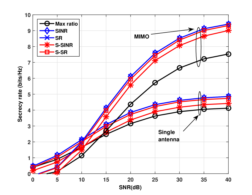
In Fig. 2 single-antenna scenario, the SINR and SR criteria have a comparable SR performance. However, the SINR criterion requires the interference knowledge and the SR criterion needs the eavesdroppers channel which are both impractical in downlink transmissions. The proposed S-SR algorithm only requires the channels to the relays and the legitimate users and can achieve almost the same SR performance as the SR criterion with full channel knowledge. The proposed S-SINR algorithm suffers a larger degradation than that of the SR criterion.
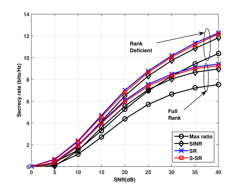
In Fig. 3, we compare the SR performance for scenarios with square and equal channel matrices and that with the zeros filled out. When we decrease the number of eavesdroppers, the SR performance increases. In this scenario, the proposed S-SR relay selection algorithm can still perform close to the SR relay selection criterion with full information.
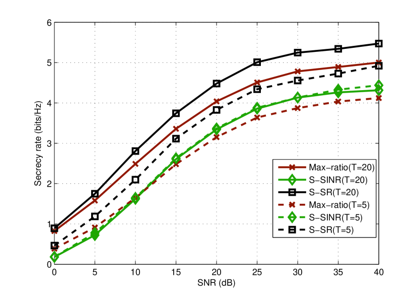
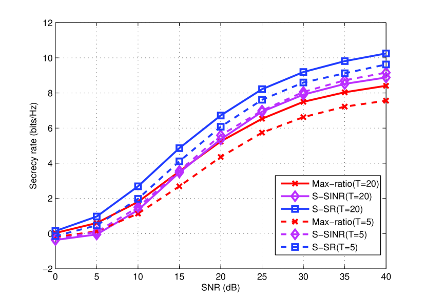
In Figure 5, simplified criteria are compared along with different numbers of relays. The S-SR criterion provides the best secrecy rate performance among all investigated criteria. With more relays distributed between the source and users, the secrecy rate performance can be further improved by employing the proposed S-SR and S-SINR criteria.
VI Conclusion
In this work, we have proposed effective multiple-relay selection algorithms for multiuser MIMO relay systems to enhance the legitimate users’ transmission. The proposed algorithms exploit the use of the available channel information to perform relay selection. Simulation results show that the proposed algorithms can provide a significantly better secrecy rate performance than existing approaches.
References
- [1] C. Shannon, “Communication theory of secrecy systems,” Bell System Technical Journal, vol. 28, no. 4, pp. 656 715, Oct 1949.
- [2] T. L. Marzetta, Noncooperative cellular wireless with unlimited numbers of base station antennas, IEEE Trans. Wireless Commun., vol. 9, no. 11, pp. 3590 3600, Nov. 2010.
- [3] R. C. de Lamare, ”Massive MIMO Systems: Signal Processing Challenges and Future Trends”, URSI Radio Science Bulletin, 2013.
- [4] A. D. Wyner, “The wire-tap channel,” Bell System Technical Journal, vol. 54, no. 8, pp. 1355 1387, 1975.
- [5] I. Csiszar and J. Korner, “Broadcast channels with confidential messages,” IEEE Trans. Inform. Theory,, vol. 24, no. 3, pp. 339 348, May 1978.
- [6] F. Oggier and B. Hassibi, “The secrecy capacity of the mimo wiretap channel,” IEEE Trans. Inform. Theory,, vol. 57, no. 8, pp. 4961 4972, Aug 2011.
- [7] T. Liu and S. Shamai, “A note on the secrecy capacity of the multipleantenna wiretap channel,” IEEE Trans. Inform. Theory,, vol. 55, no. 6, pp. 2547 2553, June 2009.
- [8] S. Goel and R. Negi, “Guaranteeing secrecy using artificial noise,” IEEE Trans. Wireless Commun., vol. 7, no. 6, pp. 2180 2189, June 2008.
- [9] J. Zhang and M. Gursoy, “Collaborative relay beamforming for secrecy,” in IEEE International Conference on Communications (ICC), May 2010, pp. 1 5.
- [10] Y. Oohama, “Capacity theorems for relay channels with confidential messages,” in IEEE International Symposium on Inform. Theory (ISIT), June 2007, pp. 926 930.
- [11] A. Mukherjee, S. Fakoorian, J. Huang, and A. Swindlehurst, “Principles of physical layer security in multiuser wireless networks: A survey,” IEEE Communications Surveys Tutorials, vol. 16, no. 3, pp. 1550 1573, August 2014.
- [12] N. Zlatanov and R. Schober, “Buffer-aided relaying with adaptive link selection-fixed and mixed rate transmission,” IEEE Trans. Inform. Theory,, vol. 59, no. 5, pp. 2816 2840, May 2013.
- [13] G. Chen, Z. Tian, Y. Gong, Z. Chen, and J. Chambers, “Max-ratio relay selection in secure buffer-aided cooperative wireless networks,” IEEE Trans. Inform. Forensics and Security,, vol. 9, no. 4, pp. 719 729, April 2014.
- [14] J. Huang and A. Swindlehurst, “Wireless physical layer security enhancement with buffer-aided relaying,” in 2013 Asilomar Conference on Signals, Systems and Computers, Nov 2013, pp. 1560 1564.
- [15] K. Zu and R. de Lamare, “Low-complexity lattice reduction-aided regularized block diagonalization for mu-mimo systems,” IEEE Communications Letters, vol. 16, no. 6, pp. 925 928, June 2012.
- [16] K. Zu, R. de Lamare, and M. Haardt, “Generalized design of lowcomplexity block diagonalization type precoding algorithms for multiuser mimo systems,” IEEE Trans. Communications, vol. 61, no. 10, pp. 4232 4242, October 2013.
- [17] K. Zu K, R. de Lamare, and M. Haardt, “Multi-branch tomlinson-harashima precoding design for mu-mimo systems: Theory and algorithms,” IEEE Trans. Communications, vol. 62, no. 3, pp. 939 951, March 2014.
- [18] X. Lu, K. Zu, and R. C.de Lamare, “Lattice-reduction aided successive optimization tomlinson-harashima precoding strategies for physical-layer security in wireless networks,” in Sensor Signal Processing for Defence (SSPD), 2014, Sept 2014, pp. 1 5.
- [19] X. Lu and R. C. Lamare, “Buffer-aided relay selection for physical-layer security in wireless networks,” in Proceedings of 19th International ITG Workshop on Smart Antennas (WSA), March 2015, pp. 1 5.
- [20] J. H. Lee and W. Choi, “Multiuser diversity for secrecy communications using opportunistic jammer selection: Secure dof and jammer scaling law,” IEEE Trans. Signal Processing,, vol. 62, no. 4, pp. 828 839, Feb 2014.
- [21] J. Chen, R. Zhang, L. Song, Z. Han, and B. Jiao, “Joint relay and jammer selection for secure two-way relay networks,” IEEE Trans. Inform. Forensics and Security,, vol. 7, no. 1, pp. 310 320, Feb 2012.
- [22] R. Aggarwal, C. E. Koksal, and P. Schniter, “On the design of large scale wireless systems”, IEEE J. Sel. Areas Commun, vol. 31, no. 2, pp. 215-225, Feb. 2013.
- [23] W. Zhang, H. Ren, C. Pan, M. Chen, R. C. de Lamare, B. Du and J. Dai, “Large-Scale Antenna Systems With UL/DL Hardware Mismatch: Achievable Rates Analysis and Calibration”, IEEE Trans. Commun., vol.63, no.4, pp. 1216-1229, April 2015.
- [24] C. Shepard, H. Yu, N. Anand, L. E. Li, T. L. Marzetta, R. Yang, and L. Zhong, Argos: Practical many-antenna base stations, in ACM Int. Conf.Mobile Computing and Networking (MobiCom), Istanbul, Turkey, Aug. 2012.
- [25] X. Gao, F. Tufvesson, O. Edfors, and F. Rusek, Measured propagation characteristics for very-large MIMO at 2.6 GHz, in Proc. of the 46th Annual Asilomar Conference on Signals, Systems, and Computers,, Pacific Grove, California, USA, Nov. 2012.
- [26] H. Q. Ngo, E. G. Larsson, and T. L. Marzetta, “Energy and spectral efficiency of very large multiuser MIMO systems”, IEEE Trans. Commun., vol. 61, no. 4, pp. 1436-1449, Apr. 2013.
- [27] H. Yang and T. L. Marzetta, Performance of conjugate and zero-forcing beamforming in large-scale antenna systems, IEEE J. Sel. Areas Commun., vol. 31, no. 2, pp. 172 179, Feb. 2013.
- [28] K. Vardhan, S. Mohammed, A. Chockalingam and B. Rajan, “A low-complexity detector for large MIMO systems and multicarrier CDMA systems”, IEEE J. Sel. Commun., vol. 26, no. 3, pp. 473-485, Apr. 2008.
- [29] P. Li and R. D. Murch, Multiple Output Selection-LAS Algorithm in Large MIMO Systems, IEEE Commun. Lett., vol. 14, no. 5, pp. 399-401, May 2010.
- [30] J. W. Choi, A. C. Singer, J Lee, N. I. Cho, Improved linear soft-input soft-output detection via soft feedback successive interference cancellation, IEEE Trans. Commun., vol.58, no.3, pp.986-996, March 2010.
- [31] P. Li, R. C. de Lamare and R. Fa, “Multiple Feedback Successive Interference Cancellation Detection for Multiuser MIMO Systems,” IEEE Transactions on Wireless Communications, vol. 10, no. 8, pp. 2434 - 2439, August 2011.
- [32] R.C. de Lamare, R. Sampaio-Neto, Minimum mean-squared error iterative successive parallel arbitrated decision feedback detectors for DS-CDMA systems , IEEE Trans. Commun., vol. 56, no. 5, May 2008, pp. 778-789.
- [33] R.C. de Lamare and R. Sampaio-Neto, “Adaptive reduced-rank equalization algorithms based on alternating optimization design techniques for MIMO systems,” IEEE Trans. Veh. Technol., vol. 60, no. 6, pp. 2482-2494, July 2011.
- [34] R. C. de Lamare, ”Adaptive and Iterative Multi-Branch MMSE Decision Feedback Detection Algorithms for Multi-Antenna Systems”, IEEE Trans. Wireless Commun., vol. 14, no. 10, October 2013.
- [35] T. Schenk, RF Imperfections in High-rate Wireless Systems: Impact and Digital Compensation, 1st ed. Springer, Feb. 2008.
- [36] S. Buzzi, M. Lops, and S. Sardellitti, “Widely linear reception strategies for layered space-time wireless communications”, IEEE Trans. Sig. Proc., vol. 54, no. 6, pp. 2252-2262, Jun. 2006.
- [37] P. Chevalier and A. Blin, “Widely linear MVDR beamformers for the reception of an unknown signal corrupted by noncircular interferences”, IEEE Trans. Sig. Proc., vol. 55, no. 11, pp. 5323 5336, Nov. 2007.
- [38] P. Chevalier and F. Dupuy, “Widely Linear Alamouti Receiver for the Reception of Real-Valued Constellations Corrupted by Interferences The Alamouti-SAIC/MAIC Concept”, IEEE Trans. Sig. Proc., Vol. 59, No. 7, July 2011.
- [39] A. Hakkarainen, J. Werner, K. R. Dandekar and M. Valkama, “Widely-linear beamforming and RF impairment suppression in massive antenna arrays,” Journal of Communications and Networks, vol.15, no.4, pp.383,397, Aug. 2013.
- [40] X. Wang and H. V. Poor, “Iterative (turbo) soft interference cancellation and decoding for coded CDMA,” IEEE Trans. Commun., vol. 47, pp. 1046 1061, July 1999.
- [41] M. Costa, “Writing on dirty paper,” IEEE Trans. Inform. Theory, vol. 29, no. 3, pp. 439-441, May 1983.
- [42] R. C. de Lamare and A. Alcaim, ”Strategies to improve the performance of very low bit rate speech coders and application to a 1.2 kb/s codec” IEE Proceedings- Vision, image and signal processing, vol. 152, no. 1, February, 2005.
- [43] P. Clarke and R. C. de Lamare, ”Joint Transmit Diversity Optimization and Relay Selection for Multi-Relay Cooperative MIMO Systems Using Discrete Stochastic Algorithms,” IEEE Communications Letters, vol.15, no.10, pp.1035-1037, October 2011.
- [44] P. Clarke and R. C. de Lamare, ”Transmit Diversity and Relay Selection Algorithms for Multirelay Cooperative MIMO Systems” IEEE Transactions on Vehicular Technology, vol.61, no. 3, pp. 1084-1098, October 2011.
- [45] Y. Cai, R. C. de Lamare, and R. Fa, “Switched Interleaving Techniques with Limited Feedback for Interference Mitigation in DS-CDMA Systems,” IEEE Transactions on Communications, vol.59, no.7, pp.1946-1956, July 2011.
- [46] Y. Cai, R. C. de Lamare, D. Le Ruyet, “Transmit Processing Techniques Based on Switched Interleaving and Limited Feedback for Interference Mitigation in Multiantenna MC-CDMA Systems,” IEEE Transactions on Vehicular Technology, vol.60, no.4, pp.1559-1570, May 2011.
- [47] T. Wang, R. C. de Lamare, and P. D. Mitchell, “Low-Complexity Set-Membership Channel Estimation for Cooperative Wireless Sensor Networks,” IEEE Transactions on Vehicular Technology, vol.60, no.6, pp.2594-2607, July 2011.
- [48] T. Wang, R. C. de Lamare and A. Schmeink, ”Joint linear receiver design and power allocation using alternating optimization algorithms for wireless sensor networks,” IEEE Trans. on Vehi. Tech., vol. 61, pp. 4129-4141, 2012.
- [49] R. C. de Lamare, “Joint iterative power allocation and linear interference suppression algorithms for cooperative DS-CDMA networks”, IET Communications, vol. 6, no. 13 , 2012, pp. 1930-1942.
- [50] T. Peng, R. C. de Lamare and A. Schmeink, “Adaptive Distributed Space-Time Coding Based on Adjustable Code Matrices for Cooperative MIMO Relaying Systems”, IEEE Transactions on Communications, vol. 61, no. 7, July 2013.
- [51] T. Peng and R. C. de Lamare, “Adaptive Buffer-Aided Distributed Space-Time Coding for Cooperative Wireless Networks,” IEEE Transactions on Communications, vol. 64, no. 5, pp. 1888-1900, May 2016.
- [52] J. Gu, R. C. de Lamare and M. Huemer, “Buffer-Aided Physical-Layer Network Coding with Optimal Linear Code Designs for Cooperative Networks,” IEEE Transactions on Communications, 2017.
- [53] W. Zhang et al., “Widely Linear Precoding for Large-Scale MIMO with IQI: Algorithms and Performance Analysis,” IEEE Transactions on Wireless Communications, vol. 16, no. 5, pp. 3298-3312, May 2017.
- [54] M. Tomlinson, ”New automatic equaliser employing modulo arithmetic,” Electronic Letters, vol. 7, Mar. 1971.
- [55] C. T. Healy and R. C. de Lamare, “Decoder-optimised progressive edge growth algorithms for the design of LDPC codes with low error floors”, IEEE Communications Letters, vol. 16, no. 6, June 2012, pp. 889-892.
- [56] A. G. D. Uchoa, C. T. Healy, R. C. de Lamare, R. D. Souza, “LDPC codes based on progressive edge growth techniques for block fading channels”, Proc. 8th International Symposium on Wireless Communication Systems (ISWCS), 2011, pp. 392-396.
- [57] A. G. D. Uchoa, C. T. Healy, R. C. de Lamare, R. D. Souza, “Generalised Quasi-Cyclic LDPC codes based on progressive edge growth techniques for block fading channels”, Proc. International Symposium Wireless Communication Systems (ISWCS), 2012, pp. 974-978.
- [58] A. G. D. Uchoa, C. T. Healy, R. C. de Lamare, R. D. Souza, “Design of LDPC Codes Based on Progressive Edge Growth Techniques for Block Fading Channels”, IEEE Communications Letters, vol. 15, no. 11, November 2011, pp. 1221-1223.
- [59] H. Harashima and H. Miyakawa, ”Matched-transmission technique for channels with intersymbol interference,” IEEE Trans. Commun., vol. 20, Aug. 1972.
- [60] K. Zu, R. C. de Lamare and M. Haardt, “Multi-branch tomlinson-harashima precoding for single-user MIMO systems,” in Smart Antennas (WSA), 2012 International ITG Workshop on , vol., no., pp.36-40, 7-8 March 2012.
- [61] K. Zu, R. C. de Lamare and M. Haardt, “Multi-Branch Tomlinson-Harashima Precoding Design for MU-MIMO Systems: Theory and Algorithms,” IEEE Transactions on Communications, vol.62, no.3, pp.939,951, March 2014.
- [62] L. Zhang, Y. Cai, R. C. de Lamare and M. Zhao, “Robust Multibranch Tomlinson Harashima Precoding Design in Amplify-and-Forward MIMO Relay Systems,” IEEE Transactions on Communications, vol.62, no.10, pp.3476,3490, Oct. 2014.
- [63] Y. Cai, R. C. de Lamare, L. L. Yang and M. Zhao, ”Robust MMSE Precoding Based on Switched Relaying and Side Information for Multiuser MIMO Relay Systems,” in IEEE Transactions on Vehicular Technology, vol. 64, no. 12, pp. 5677-5687, Dec. 2015.
- [64] B. Hochwald, C. Peel and A. Swindlehurst, ”A vector-perturbation technique for near capacity multiantenna multiuser communication - Part II: Perturbation,” IEEE Trans. Commun., vol. 53, no. 3, Mar. 2005.
- [65] C. B. Chae, S. Shim and R. W. Heath, ”Block diagonalized vector perturbation for multiuser MIMO systems,” IEEE Trans. Wireless Commun., vol. 7, no. 11, pp. 4051 - 4057, Nov. 2008.
- [66] R. C. de Lamare, R. Sampaio-Neto, “Adaptive MBER decision feedback multiuser receivers in frequency selective fading channels”, IEEE Communications Letters, vol. 7, no. 2, Feb. 2003, pp. 73 - 75.
- [67] A. Rontogiannis, V. Kekatos, and K. Berberidis,” A Square-Root Adaptive V-BLAST Algorithm for Fast Time-Varying MIMO Channels,” IEEE Signal Processing Letters, Vol. 13, No. 5, pp. 265-268, May 2006.
- [68] R. C. de Lamare, R. Sampaio-Neto, A. Hjorungnes, “Joint iterative interference cancellation and parameter estimation for CDMA systems”, IEEE Communications Letters, vol. 11, no. 12, December 2007, pp. 916 - 918.
- [69] Y. Cai and R. C. de Lamare, ”Adaptive Space-Time Decision Feedback Detectors with Multiple Feedback Cancellation”, IEEE Transactions on Vehicular Technology, vol. 58, no. 8, October 2009, pp. 4129 - 4140.
- [70] J. W. Choi, A. C. Singer, J Lee, N. I. Cho, “Improved linear soft-input soft-output detection via soft feedback successive interference cancellation,” IEEE Trans. Commun., vol.58, no.3, pp.986-996, March 2010.
- [71] R. C. de Lamare and R. Sampaio-Neto, “Blind adaptive MIMO receivers for space-time block-coded DS-CDMA systems in multipath channels using the constant modulus criterion,” IEEE Transactions on Communications, vol.58, no.1, pp.21-27, January 2010.
- [72] R. Fa, R. C. de Lamare, “Multi-Branch Successive Interference Cancellation for MIMO Spatial Multiplexing Systems”, IET Communications, vol. 5, no. 4, pp. 484 - 494, March 2011.
- [73] P. Li, R. C. de Lamare and J. Liu, “Adaptive Decision Feedback Detection with Parallel Interference Cancellation and Constellation Constraints for Multiuser MIMO systems”, IET Communications, vol.7, 2012, pp. 538-547.
- [74] J. Liu, R. C. de Lamare, “Low-Latency Reweighted Belief Propagation Decoding for LDPC Codes,” IEEE Communications Letters, vol. 16, no. 10, pp. 1660-1663, October 2012.
- [75] C. T. Healy and R. C. de Lamare, “Design of LDPC Codes Based on Multipath EMD Strategies for Progressive Edge Growth,” IEEE Transactions on Communications, vol. 64, no. 8, pp. 3208-3219, Aug. 2016.
- [76] P. Li and R. C. de Lamare, Distributed Iterative Detection With Reduced Message Passing for Networked MIMO Cellular Systems, IEEE Transactions on Vehicular Technology, vol.63, no.6, pp. 2947-2954, July 2014.
- [77] A. G. D. Uchoa, C. T. Healy and R. C. de Lamare, “Iterative Detection and Decoding Algorithms For MIMO Systems in Block-Fading Channels Using LDPC Codes,” IEEE Transactions on Vehicular Technology, 2015.
- [78] R. C. de Lamare, “Adaptive and Iterative Multi-Branch MMSE Decision Feedback Detection Algorithms for Multi-Antenna Systems”, IEEE Trans. Wireless Commun., vol. 14, no. 10, October 2013.
- [79] J. Gu and R. C. de Lamare, “Joint interference cancellation and relay selection algorithms based on greedy techniques for cooperative DS-CDMA systems”, EURASIP Journal on Wireless Communications and Networking, December 2016.
- [80] L. L. Scharf and D. W. Tufts, “Rank reduction for modeling stationary signals,” IEEE Transactions on Acoustics, Speech and Signal Processing, vol. ASSP-35, pp. 350-355, March 1987.
- [81] A. M. Haimovich and Y. Bar-Ness, “An eigenanalysis interference canceler,” IEEE Trans. on Signal Processing, vol. 39, pp. 76-84, Jan. 1991.
- [82] D. A. Pados and S. N. Batalama ”Joint space-time auxiliary vector filtering for DS/CDMA systems with antenna arrays” IEEE Transactions on Communications, vol. 47, no. 9, pp. 1406 - 1415, 1999.
- [83] J. S. Goldstein, I. S. Reed and L. L. Scharf ”A multistage representation of the Wiener filter based on orthogonal projections” IEEE Transactions on Information Theory, vol. 44, no. 7, 1998.
- [84] Y. Hua, M. Nikpour and P. Stoica, ”Optimal reduced rank estimation and filtering,” IEEE Transactions on Signal Processing, pp. 457-469, Vol. 49, No. 3, March 2001.
- [85] M. L. Honig and J. S. Goldstein, “Adaptive reduced-rank interference suppression based on the multistage Wiener filter,” IEEE Transactions on Communications, vol. 50, no. 6, June 2002.
- [86] E. L. Santos and M. D. Zoltowski, “On Low Rank MVDR Beamforming using the Conjugate Gradient Algorithm”, Proc. IEEE International Conference on Acoustics, Speech and Signal Processing, 2004.
- [87] Q. Haoli and S.N. Batalama, “Data record-based criteria for the selection of an auxiliary vector estimator of the MMSE/MVDR filter”, IEEE Transactions on Communications, vol. 51, no. 10, Oct. 2003, pp. 1700 - 1708.
- [88] R. C. de Lamare and R. Sampaio-Neto, “Reduced-Rank Adaptive Filtering Based on Joint Iterative Optimization of Adaptive Filters”, IEEE Signal Processing Letters, Vol. 14, no. 12, December 2007.
- [89] Z. Xu and M.K. Tsatsanis, “Blind adaptive algorithms for minimum variance CDMA receivers,” IEEE Trans. Communications, vol. 49, No. 1, January 2001.
- [90] R. C. de Lamare and R. Sampaio-Neto, “Low-Complexity Variable Step-Size Mechanisms for Stochastic Gradient Algorithms in Minimum Variance CDMA Receivers”, IEEE Trans. Signal Processing, vol. 54, pp. 2302 - 2317, June 2006.
- [91] C. Xu, G. Feng and K. S. Kwak, “A Modified Constrained Constant Modulus Approach to Blind Adaptive Multiuser Detection,” IEEE Trans. Communications, vol. 49, No. 9, 2001.
- [92] Z. Xu and P. Liu, “Code-Constrained Blind Detection of CDMA Signals in Multipath Channels,” IEEE Sig. Proc. Letters, vol. 9, No. 12, December 2002.
- [93] R. C. de Lamare and R. Sampaio Neto, ”Blind Adaptive Code-Constrained Constant Modulus Algorithms for CDMA Interference Suppression in Multipath Channels”, IEEE Communications Letters, vol 9. no. 4, April, 2005.
- [94] L. Landau, R. C. de Lamare and M. Haardt, “Robust adaptive beamforming algorithms using the constrained constant modulus criterion,” IET Signal Processing, vol.8, no.5, pp.447-457, July 2014.
- [95] R. C. de Lamare, “Adaptive Reduced-Rank LCMV Beamforming Algorithms Based on Joint Iterative Optimisation of Filters”, Electronics Letters, vol. 44, no. 9, 2008.
- [96] R. C. de Lamare and R. Sampaio-Neto, “Adaptive Reduced-Rank Processing Based on Joint and Iterative Interpolation, Decimation and Filtering”, IEEE Transactions on Signal Processing, vol. 57, no. 7, July 2009, pp. 2503 - 2514.
- [97] R. C. de Lamare and Raimundo Sampaio-Neto, “Reduced-rank Interference Suppression for DS-CDMA based on Interpolated FIR Filters”, IEEE Communications Letters, vol. 9, no. 3, March 2005.
- [98] R. C. de Lamare and R. Sampaio-Neto, “Adaptive Reduced-Rank MMSE Filtering with Interpolated FIR Filters and Adaptive Interpolators”, IEEE Signal Processing Letters, vol. 12, no. 3, March, 2005.
- [99] R. C. de Lamare and R. Sampaio-Neto, “Adaptive Interference Suppression for DS-CDMA Systems based on Interpolated FIR Filters with Adaptive Interpolators in Multipath Channels”, IEEE Trans. Vehicular Technology, Vol. 56, no. 6, September 2007.
- [100] R. C. de Lamare, “Adaptive Reduced-Rank LCMV Beamforming Algorithms Based on Joint Iterative Optimisation of Filters,” Electronics Letters, 2008.
- [101] R. C. de Lamare and R. Sampaio-Neto, “Reduced-rank adaptive filtering based on joint iterative optimization of adaptive filters”, IEEE Signal Process. Lett., vol. 14, no. 12, pp. 980-983, Dec. 2007.
- [102] R. C. de Lamare, M. Haardt, and R. Sampaio-Neto, “Blind Adaptive Constrained Reduced-Rank Parameter Estimation based on Constant Modulus Design for CDMA Interference Suppression”, IEEE Transactions on Signal Processing, June 2008.
- [103] M. Yukawa, R. C. de Lamare and R. Sampaio-Neto, “Efficient Acoustic Echo Cancellation With Reduced-Rank Adaptive Filtering Based on Selective Decimation and Adaptive Interpolation,” IEEE Transactions on Audio, Speech, and Language Processing, vol.16, no. 4, pp. 696-710, May 2008.
- [104] R. C. de Lamare and R. Sampaio-Neto, “Reduced-rank space-time adaptive interference suppression with joint iterative least squares algorithms for spread-spectrum systems,” IEEE Trans. Vehi. Technol., vol. 59, no. 3, pp. 1217-1228, Mar. 2010.
- [105] R. C. de Lamare and R. Sampaio-Neto, “Adaptive reduced-rank equalization algorithms based on alternating optimization design techniques for MIMO systems,” IEEE Trans. Vehi. Technol., vol. 60, no. 6, pp. 2482-2494, Jul. 2011.
- [106] R. C. de Lamare, L. Wang, and R. Fa, “Adaptive reduced-rank LCMV beamforming algorithms based on joint iterative optimization of filters: Design and analysis,” Signal Processing, vol. 90, no. 2, pp. 640-652, Feb. 2010.
- [107] R. Fa, R. C. de Lamare, and L. Wang, “Reduced-Rank STAP Schemes for Airborne Radar Based on Switched Joint Interpolation, Decimation and Filtering Algorithm,” IEEE Transactions on Signal Processing, vol.58, no.8, Aug. 2010, pp.4182-4194.
- [108] L. Wang and R. C. de Lamare, ”Low-Complexity Adaptive Step Size Constrained Constant Modulus SG Algorithms for Blind Adaptive Beamforming”, Signal Processing, vol. 89, no. 12, December 2009, pp. 2503-2513.
- [109] L. Wang and R. C. de Lamare, “Adaptive Constrained Constant Modulus Algorithm Based on Auxiliary Vector Filtering for Beamforming,” IEEE Transactions on Signal Processing, vol. 58, no. 10, pp. 5408-5413, Oct. 2010.
- [110] L. Wang, R. C. de Lamare, M. Yukawa, ”Adaptive Reduced-Rank Constrained Constant Modulus Algorithms Based on Joint Iterative Optimization of Filters for Beamforming,” IEEE Transactions on Signal Processing, vol.58, no.6, June 2010, pp.2983-2997.
- [111] L. Wang, R. C. de Lamare and M. Yukawa, “Adaptive reduced-rank constrained constant modulus algorithms based on joint iterative optimization of filters for beamforming”, IEEE Transactions on Signal Processing, vol.58, no. 6, pp. 2983-2997, June 2010.
- [112] L. Wang and R. C. de Lamare, “Adaptive constrained constant modulus algorithm based on auxiliary vector filtering for beamforming”, IEEE Transactions on Signal Processing, vol. 58, no. 10, pp. 5408-5413, October 2010.
- [113] R. Fa and R. C. de Lamare, “Reduced-Rank STAP Algorithms using Joint Iterative Optimization of Filters,” IEEE Transactions on Aerospace and Electronic Systems, vol.47, no.3, pp.1668-1684, July 2011.
- [114] Z. Yang, R. C. de Lamare and X. Li, “L1-Regularized STAP Algorithms With a Generalized Sidelobe Canceler Architecture for Airborne Radar,” IEEE Transactions on Signal Processing, vol.60, no.2, pp.674-686, Feb. 2012.
- [115] Z. Yang, R. C. de Lamare and X. Li, “Sparsity-aware space time adaptive processing algorithms with L1-norm regularisation for airborne radar”, IET signal processing, vol. 6, no. 5, pp. 413-423, 2012.
- [116] Neto, F.G.A.; Nascimento, V.H.; Zakharov, Y.V.; de Lamare, R.C., ”Adaptive re-weighting homotopy for sparse beamforming,” in Signal Processing Conference (EUSIPCO), 2014 Proceedings of the 22nd European , vol., no., pp.1287-1291, 1-5 Sept. 2014
- [117] Almeida Neto, F.G.; de Lamare, R.C.; Nascimento, V.H.; Zakharov, Y.V.,“Adaptive reweighting homotopy algorithms applied to beamforming,” IEEE Transactions on Aerospace and Electronic Systems, vol.51, no.3, pp.1902-1915, July 2015.
- [118] L. Wang, R. C. de Lamare and M. Haardt, “Direction finding algorithms based on joint iterative subspace optimization,” IEEE Transactions on Aerospace and Electronic Systems, vol.50, no.4, pp.2541-2553, October 2014.
- [119] S. D. Somasundaram, N. H. Parsons, P. Li and R. C. de Lamare, “Reduced-dimension robust capon beamforming using Krylov-subspace techniques,” IEEE Transactions on Aerospace and Electronic Systems, vol.51, no.1, pp.270-289, January 2015.
- [120] S. Xu and R.C de Lamare, , Distributed conjugate gradient strategies for distributed estimation over sensor networks, Sensor Signal Processing for Defense SSPD, September 2012.
- [121] S. Xu, R. C. de Lamare, H. V. Poor, “Distributed Estimation Over Sensor Networks Based on Distributed Conjugate Gradient Strategies”, IET Signal Processing, 2016 (to appear).
- [122] S. Xu, R. C. de Lamare and H. V. Poor, Distributed Compressed Estimation Based on Compressive Sensing, IEEE Signal Processing letters, vol. 22, no. 9, September 2014.
- [123] S. Xu, R. C. de Lamare and H. V. Poor, “Distributed reduced-rank estimation based on joint iterative optimization in sensor networks,” in Proceedings of the 22nd European Signal Processing Conference (EUSIPCO), pp.2360-2364, 1-5, Sept. 2014
- [124] S. Xu, R. C. de Lamare and H. V. Poor, “Adaptive link selection strategies for distributed estimation in diffusion wireless networks,” in Proc. IEEE International Conference onAcoustics, Speech and Signal Processing (ICASSP), , vol., no., pp.5402-5405, 26-31 May 2013.
- [125] S. Xu, R. C. de Lamare and H. V. Poor, “Dynamic topology adaptation for distributed estimation in smart grids,” in Computational Advances in Multi-Sensor Adaptive Processing (CAMSAP), 2013 IEEE 5th International Workshop on , vol., no., pp.420-423, 15-18 Dec. 2013.
- [126] S. Xu, R. C. de Lamare and H. V. Poor, “Adaptive Link Selection Algorithms for Distributed Estimation”, EURASIP Journal on Advances in Signal Processing, 2015.
- [127] N. Song, R. C. de Lamare, M. Haardt, and M. Wolf, “Adaptive Widely Linear Reduced-Rank Interference Suppression based on the Multi-Stage Wiener Filter,” IEEE Transactions on Signal Processing, vol. 60, no. 8, 2012.
- [128] N. Song, W. U. Alokozai, R. C. de Lamare and M. Haardt, “Adaptive Widely Linear Reduced-Rank Beamforming Based on Joint Iterative Optimization,” IEEE Signal Processing Letters, vol.21, no.3, pp. 265-269, March 2014.
- [129] R.C. de Lamare, R. Sampaio-Neto and M. Haardt, ”Blind Adaptive Constrained Constant-Modulus Reduced-Rank Interference Suppression Algorithms Based on Interpolation and Switched Decimation,” IEEE Trans. on Signal Processing, vol.59, no.2, pp.681-695, Feb. 2011.
- [130] Y. Cai, R. C. de Lamare, “Adaptive Linear Minimum BER Reduced-Rank Interference Suppression Algorithms Based on Joint and Iterative Optimization of Filters,” IEEE Communications Letters, vol.17, no.4, pp.633-636, April 2013.
- [131] R. C. de Lamare and R. Sampaio-Neto, “Sparsity-Aware Adaptive Algorithms Based on Alternating Optimization and Shrinkage,” IEEE Signal Processing Letters, vol.21, no.2, pp.225,229, Feb. 2014.