Interfacial exchange coupling induced chiral symmetry-breaking of Spin-Orbit effects
Abstract
We demonstrate that the interfacial exchange coupling in ferromagnetic/antiferromagnetic (FM/AFM) systems induces symmetry-breaking of the Spin-Orbit (SO) effects. This has been done by studying the field and angle dependencies of anisotropic magnetoresistance and vectorial-resolved magnetization hysteresis loops, measured simultaneously and reproduced with numerical simulations. We show how the induced unidirectional magnetic anisotropy at the FM/AFM interface results in strong asymmetric transport behaviors, which are chiral around the magnetization hard-axis direction. Similar asymmetric features are anticipated in other SO-driven phenomena.
pacs:
75.70.Tj, 71.70.Gm, 75.30.Gw, 75.60.JkThe Spin-Orbit (SO) interaction arises from the coupling of the electron spin with its orbital motion mcguire_IEEE_1975 . SO effects influence both magnetic and transport properties and constitute the subject of modern nanomagnetism. The microscopic origin of the magnetic anisotropy of ferromagnetic (FM) systems ultimately arises from SO fernando_book2008 , dictating the preferential magnetization directions. In FM/heavy metal structures, interfacial SO promotes a perpendicular magnetic anisotropy (PMA) storJMMM1999 and it is responsible of chiral spin reversals bogdanov_PRL_2001 , due to the Dzyaloshinskii-Moriya interaction (DMI) Fert_DMI . The SO interaction is exploited nowadays in spintronic applications fert_Nat2007 , since it produces a mixing of the electron spin-up and spin-down states determining anisotropic magnetoresistive signals. In addition, SO-induced spin Hall effects may be exploited to efficiently manipulate and sense the magnetization in future spin-orbitronic applications axel_IEEE2013 . In any case, the transport phenomena are strongly influenced by the effective symmetry of the SO effects. Therefore, determining their general features represents a crucial step towards the understanding and the improvement of their functionalities.
In FM films with (two-fold) uniaxial magnetic anisotropy () SO determines symmetric magnetoresistance (MR) responses around the magnetization easy-axis (e.a.) and hard-axis (h.a.) directions pernaAPL_2014 : MRMRMR, where is the angle of the external applied magnetic field with respect to the anisotropy direction. This is the anisotropic magnetoresistance (AMR), which depends on the angle enclosed by the magnetization vector (M) and the injected electrical current (J) following a law. Uniaxial systems present symmetric magnetization reversal pathways and hence symmetric MR responses. In this sense, a magnetic symmetry-breaking could promote non-symmetric reversals and MR responses. For instance, a FM layer exchange coupled with an antiferromagnet (AFM) layer presents an additional (one-fold) unidirectional magnetic anisotropy () nogues_JMMM1999 , which is generally revealed through a shift of the hysteresis loop of the FM layer, called exchange-bias (EB) field, and an enhancement of the coercivity. From a technological point of view, EB is largely exploited in spintronics because it satisfies the need for stable and controlled MR outputs in magnetic recording, processing, and sensing devices. Systematic studies have shown how this interfacial exchange coupling modifies the magnetization reversal pathways camarero_prl2005 ; camarero_prb2009 . The transport properties have also been studied, but only for several fixed magnetic-field values and/or field directions miller_APL1996 ; brems_prl2007 ; Gruyters_JAP2004 ; Mattheis_IEEE2002 .
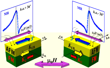
In this Letter we show that the interfacial exchange coupling in FM/AFM systems strongly influences the SO effects thus promoting asymmetric MR responses, which are chiral with respect to the h.a. direction, as Fig. 1 illustrates. Angular- and field-dependent measurements of the MR and the magnetization reversal pathways (measured simultaneously) have been reproduced with numerical simulations without any free parameter. We show how the symmetry of the MR response of an uniaxial FM system is broken by the unidirectional exchange coupling imposed by an adjacent AFM layer. In particular, symmetric MR responses are only found at characteristic magnetization directions (e.a. and h.a.). Identical and chiral MR responses are observed around the e.a. and h.a. direction, respectively. Asymmetric magneto-transport behaviors produced by unidirectional symmetry- breaking found in other spin-orbitronic systems are also discussed.
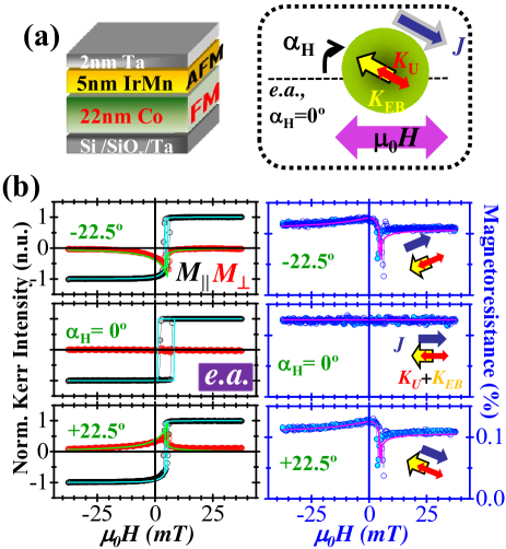
The scheme of the FM/AFM sample structure and the experimental configuration are shown in Fig. 2(a). Details on the fabrication of the FM/AFM bilayers and reference FM films, with collinear uniaxial and unidirectional are reported in Suppl. Material supplemental . Here, we refer to 22 nm Co/5 nm IrMn bilayer because it presents the smallest anisotropy field supplemental .
The magnetic and transport properties were studied at RT by investigating the angular- and field-dependence of magnetization reversal pathways and magnetoresistive responses. Vectorial-resolved magnetization and resistance signals were acquired simultaneously as a function of the magnetic field for a given field orientation () pernaAPL_2014 . refers when the anisotropy axis is oriented parallel to the external field (Fig. 2(a)). The magnetization components, parallel () and perpendicular () to the external field, were derived from vectorial-resolved magneto optic Kerr effect measurements supplemental ; MOKE ; perna_jap11 . The magnetoresistance (MR) was measured by using a lock-in amplifier in a four probe method with the electrical current vector set parallel to the anisotropy axis (see Sec. II in supplemental ). The measurements were performed in the whole angular range. In general, the magnetization reverses via sharp irreversible (and smooth reversible) transitions, indicative of nucleation and propagation of magnetic domains (magnetization rotation) perna_NJP . The relevance of this refers to the proximity to the e.a. (h.a.) direction. Consequently, MR depends strongly on .
The correlation between magnetic and transport properties and the general trends are determined from the comparison of the symmetry relationships between them. This will be discussed in detail in the following, first by comparing field-dependent curves at selected angles around the characteristic e.a. (Fig. 2(b)) and h.a. (Fig. 3 and Fig. 4) directions and then by comparing angle-dependent curves at selected fields (Fig. 5). It is worth to remark that the high symmetry found in the magnetotransport properties of a FM layer with uniaxial magnetic anisotropy is no longer satisfied in the FM/AFM system. At first glance, symmetric features in both magnetic and transport properties are found only at the easy and hard direction. In any other angular conditions, both magnetic and MR curves are strongly asymmetric.
Fig. 2(b) compares representative vectorial-resolved magnetization (left panels) and magnetoresistance (right panels) hysteresis loops acquired simultaneously at selected around the e.a. At (central left panel), - presents a shifted ( mT) squared shape hysteresis loop with a sharp irreversible jump at mT, whereas the - is negligible in the whole field loop. Away from the e.a., and reverses only in one semicircle, and above a critical angle, which depends on the ratio camarero_prl2005 , the magnetization reversal becomes fully reversible. Therefore, close to e.a. direction nucleation and propagation of magnetic domains are the relevant processes. The right panels in Fig. 2(b) display the corresponding transport measurements. At the e.a. the MR- curve is symmetric (and flat) in the whole field loop, whereas non-symmetric curves are found for . As will be discussed below, similar features are found for - and MR- around the e.a. direction.
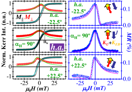
Fig. 3 shows a similar study close to the h.a. In general, both and loops show smooth reversible transitions, indicating that magnetization rotation is the relevant process during reversal. M rotates in-plane only in one semicircle during the reversal, so that the angle between M and J is continuously changing as the field is sweeping. At the h.a. (central panels of Fig. 3), displays a nearby linear behavior, with an anisotropy field mT (see Sec. III of supplemental ), whereas MR shows the maximum variation, which yields to . In addition, the - curve show rotational symmetry whereas - and MR- curves are mirror symmetric with respect to zero field. However, these symmetric features are lost away from the h.a. direction.
Around the characteristic directions different symmetry relationships are identified. For instance, for , that is around the e.a. direction (Fig. 2(b)), and MR loops display identical field dependent evolution, i.e., and MRMR, whereas the experiences a sign change . In turn, around the h.a. direction, e.g., for (Fig. 3), the hysteresis curves of the parallel component are identical under rotation around the origin, i.e., , whereas the hysteresis curves of the perpendicular component and the MR display chiral asymmetry, i.e. and . This (2-dimensional) chiral asymmetry is schematically illustrated in (Fig. 1).
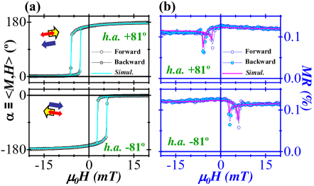
The chiral asymmetry is not only found closely around h.a., where the magnetization reversal is governed by magnetization rotation processes, but is extended in the whole angular range. Fig. 4 shows the magnetic and transport behaviors for two selected field directions around the h.a., , but very close to the e.a. direction, where reversal is governed by nucleation and propagation of domains. In this case, Fig. 4(a) displays the hysteresis curves of the angle of the magnetization vector with respect to the current direction extracted directly from the vectorial-Kerr data. This angle defines the magnetic torque. The corresponding resistance changes are shown in Fig. 4(b). In general, the MR loops present pronounced MR peaks meanwhile the magnetization switches from to . There is an asymmetry between the forward (descending) and backward (ascending) field branches in both magnetic and transport behaviors. This originates from the interfacial-induced unidirectional anisotropy which results with more rounded transitions and with higher MR peaks when the field sweeps against the unidirectional anisotropy camarero_prl2005 ; brems_prl2007 . Moreover, the chiral asymmetry is preserved, i.e., MR(h.a.)=MR(h.a.. This indicates that this asymmetry is independent of the reversal mechanism.
To gain further insight into the symmetry-breaking of the SO effects, we have performed numerical simulations by using a modified coherent rotation Stoner-Wohlfarth (SW) model (with no free parameters) in which we included collinear uniaxial and unidirectional anisotropy terms with (see Secs. III and IV of supplemental ). This allows us to simulate the angular and magnetic field dependence of the magnetization reversal pathways camarero_prb2009 , i.e., , , and to derive the corresponding MR responses according to MR, where . The simulated hysteresis curves are superimposed (continuous black lines in Figs. 2(b), 3 and 4) to the experimental curves. There is a perfect agreement between them, including their asymmetries, which demonstrates that both magnetization pathways and magnetoresistance responses are strongly affected by the system symmetry.
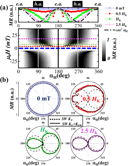
The broken-symmetry of the SO effects can be clearly observed by plotting the whole angular evolution of the MR- hysteresis loops in a 2D map representation (Fig. 5(a)). Such plot allows visualizing the broken periodicity. While the well-defined uniaxial (two-fold) magnetic anisotropy of a FM results with a periodicity pernaAPL_2014 , the additional unidirectional (one-fold) anisotropy induced at the FM/AFM interface promotes the symmetry-breaking of the SO effects supplemental , resulting with a periodicity.
In order to visualize the angle dependence of MR, different horizontal cuts of the 2D map have been plotted in the top graph in Fig. 5(a). This represents the angular evolution of MR at different magnetic field values. At remanence (i.e., mT, blue empty-circles) the MR signal comes out from a configuration in the whole angular range and therefore it does not change. For non-zero external field, the angular dependence of the MR is clearly asymmetric, as the mirror symmetry along the horizontal axis is completely broken. From a simple inspection of the top graph of Fig. 5(a), we can figure out relevant information. First, the maximum values of the MR are found when is aligned along the anisotropy direction. M is parallel to J only in a small range of angles, which increases as the external field increases. Away from the anisotropy direction, the MR value decreases gradually and it is minimum where the angle between M and J approaches to . Second, larger MR changes are found as the external field increases. Third, the MR displays identical or different (asymmetry) values around the anisotropy or h.a. direction, respectively. The asymmetry vanishes for very large external magnetic fields compared to the anisotropy field, where the angle dependence of MR approaches a law.
The discussed trends and symmetry-breaking SO effects are also reflected in the corresponding polar plot representation of the MR shown in Fig. 5(b). Each graph includes both experimental (symbols) and simulated (lines) data. The latter includes model uniaxial (SW ) and exchange-biased (SW ) systems. In remanence conditions, both models are indistinguishable, i.e., circular-shaped polar plot with no MR variation. For , the simulated polar plots of the uniaxial system display a similar two-lobe behavior, which result with mirror symmetry with respect to both e.a. and h.a. directions. In contrast, the simulated polar plots of the exchange-biased system show mirror symmetry with respect the e.a. direction and a (chiral) asymmetry with respect to the h.a. direction. The asymmetry diminishes as the external field increases, vanishing for very large fields compared with the anisotropy field. Remarkably, all experimental data are very well reproduced by the model (see also Sec. IV of supplemental ).
Asymmetric transport and magnetic behaviors, originating from interfacial symmetry-breaking (unidirectional) effects, can also be found in other magnetic systems. For instance, exchange-biased spin valves display chiral symmetry in both magnetization and giant magnetoresistance loops around the h.a. direction (see graph panels of Fig. 2 in pernaPRB_2012 ), as well as asymmetric MR curves were found in exchange-biased multiferroic BiFeO3-based systems allibe_nanoLett2012 . In addition, fixed chiral spin structures can be stabilized in PMA systems with sizeable DMI chen_PRL2013 , and in the presence of an in-plane magnetic field, producing asymmetric magnetization reversal features during (chiral) magnetic domain nucleation pizzini_PRL2013 and domain propagation hrabec_PRB2014 . On the other hand, in FM/HM systems with in-plane magnetization, SO-dependent effective in-plane field has been demonstrated giving rise to asymmetric reversal fan_natcomm2013 . Asymmetric planar Hall margin_scierep2015 and inverse spin Hall hammel_PRB2014 effect signals have also been recently reported in exchange-biased insulating FM/metallic AFM bilayers, as well as asymmetries in the spin Hall magnetoresistance has been found in SrMnO3/Pt pan_PRB2013 . These asymmetric signals, which are generally clearly observed at low-magnetic fields, arise from the SO coupling in presence of an unidirectional magnetic anisotropy. In the large field regime the asymmetries vanish, in agreement with our results.
In summary, we have demonstrated the existence of broken-symmetry of the SO effects due to the exchange interaction at the FM/AFM interface, which is responsible of asymmetries in both magnetic and transport properties. In particular, we have shown an intrinsic chiral asymmetry in the MR with respect to the magnetization hard-axis direction. Similar effects can be envisaged for other both spintronic and spin-orbitronic systems when either intrinsic magnetic anisotropy or the SO interaction presents symmetry-breaking.
This work was supported in part by the Spanish MINECO through Project No. MAT2012-39308, FIS2013-40667-P, MAT2011-25598 and MAT2014-52477-C5-3-P, and by the Comunidad de Madrid through Project S2013/MIT-2850 (NANOFRONTMAG-CM). P.P. and A.B. acknowledge support through the Marie Curie AMAROUT EU Programme, and through ”Juan de la Cierva” (JCI-2011-09602) and the ”Ramón y Cajal” contract from the Spanish MICINN, respectively.
References
- (1) T. R. McGuire & R. I. Potter, IEEE Trans. Magn. 11, 1018 (1975).
- (2) G. Fernando, Metallic Multilayers and their Applications, edited by Prasanta Misra, included in series Handbook of Metal Physics, Elsevier ISBN: 978-0-444-51703-6 (2008).
- (3) J. Stöhr, J. Magn Magn. Mater. 200, 470 (1999).
- (4) A. N. Bogdanov and U. K. Rößler, Phys. Rev. Lett. 87, 037203 (2001).
- (5) A. Fert, Mater. Sci. Forum 5960, 439480 (1990); A. Fert, and P.M. Levy, Phys. Rev. Lett. 44, 1538 (1980); A. Fert, V. Cros, and J. Sampaio, Nature Nanotech. 8, 152-156 (2013).
- (6) C. Chappert, A. Fert & F. Nguyen Van Dau, Nature Mater. 6, 813 (2007).
- (7) A. Hoffmann, IEEE Trans. Magn. 49, 5172 (2013).
- (8) P. Perna, D. Maccariello, C. Rodrigo, J.L.F. Cuñado, M. Muñoz, J.L. Prieto, M.A. Niño, A. Bollero, J. Camarero, and R. Miranda, Appl. Phys. Lett. 104, 202407 (2014).
- (9) J. Nogues and I. K. Schuller, J. Magn. Magn. Mater. 192, 203 (1999).
- (10) J. Camarero, et al., Phys. Rev. Lett. 95, 057204 (2005).
- (11) E. Jiménez, et al., Phys. Rev. B 80, 014415 (2009).
- (12) B. H. Miller and E. Dan Dahlberg, Appl. Phys. Lett. 69, 3932 (1996)
- (13) S. Brems, K. Temst, and C. Van Haesendonck, Phys. Rev. Lett. 99, 067201 (2007).
- (14) M. Gruyters, J. Appl. Phys. 95, 2587 (2004).
- (15) K.-U. Barholz and R. Mattheis, IEEE Trans. Magn. 38, 2767 (2002).
- (16) Supplementary information available at http://xxxxxx provides detailed information on experimental/simulation procedures and extended data.
- (17) E. Jiménez, et al., Rev. Sci. Instrum. 85, 053904 (2014); J. L. Cuñado, et al., Rev. Sci. Instrum. 86, 046109 (2015).
- (18) P. Perna, et al., J. Appl. Phys. 110, 13919 (2011); ibid. J. Appl. Phys. 109, 07B107 (2011).
- (19) P. Perna, L. Méchin, M. Saïb, J. Camarero and S. Flament, New J. Phys. 12, 103033 (2010).
- (20) P. Perna, C. Rodrigo, M. Muñoz, J. L. Prieto, A. Bollero, D. Maccariello, J. L. F. Cuñado, M. Romera, J. Akerman, E. Jiménez, N. Mikuszeit, V. Cros, J. Camarero, and R. Miranda, Phys. Rev. B 86, 024421 (2012).
- (21) J. Allibe, S. Fusil, K. Bouzehouane, C. Daumont, D. Sando, E. Jacquet, C. Deranlot, M. Bibes, and A. Barthelemy, Nano Lett. 12, 1141 (2012).
- (22) G. Chen, J. Zhu, A. Quesada, J. Li, A.T. NDiaye, Y. Huo, T.P. Ma, Y. Chen, H.Y. Kwon, C. Won, Z.Q. Qiu, A.K. Schmid, and Y.Z. Wu, Phys. Rev. Lett. 110, 177204 (2013).
- (23) S. Pizzini, J. Vogel, S. Rohart, L. D. Buda-Prejbeanu, E. Jué, O. Boulle, I. M. Miron, C. K. Safeer, S. Auffret, G. Gaudin, and A. Thiaville, Phys. Rev. Lett. 113, 047203 (2014).
- (24) A. Hrabec, N. A. Porter, A. Wells, M. J. Benitez, G. Burnell, S. McVitie, D. McGrouther, T. A. Moore, and C. H. Marrows, Phys. Rev. B 90, 020402(R) (2014).
- (25) X. Fan, J. Wu, Y. Chen, M. J. Jerry, H. Zhang, and J. Q. Xiao, Nature Comms. 4, 1799 (2013).
- (26) X. Zhou, L. Ma, Z. Shi, W. J. Fan, R. F. L. Evans, Jian-Guo Zheng, R. W. Chantrell, S. Mangin, H. W. Zhang and S. M. Zhou, Sci. Rep. 5, 9183 (2015).
- (27) C. Du, H. Wang, F. Yang, and P. C. Hammel, Phys. Rev. B 90, 140407(R) (2014).
- (28) J. H. Han, C. Song, F. Li, Y. Y. Wang, G. Y. Wang, Q. H. Yang, and F. Pan, Phys. Rev. B 90, 144431 (2014).