Determining the duration of an intense laser pulse directly in focus
Abstract
We propose a novel measurement technique capable of determining the temporal duration of an intense laser pulse directly in its focus at full intensity. We show that the electromagnetic radiation pattern emitted by an electron bunch with a temporal energy chirp colliding perpendicularly with the laser pulse exhibits a distinct dependence on the pulse’s duration. As the electrons emit radiation into an angular region determined by the ratio of their instantaneous energy to the laser’s local field strength, the temporal change of the electrons’ energy imprints information about the laser’s pulse duration onto the angular radiation distribution. We quantify the interaction by a simplified analytical model and confirm this model’s predictions by numerical simulations of the electrons’ dynamics inside a realistically focused laser field. Based on these findings the pulse’s duration can be determined to an accuracy of several percent.
Introduction - The development of lasers towards ever higher intensities, motivated by their utility as tools for studies of fundamental physics DiPiazza_etal_2012 ; ELI_WhiteBook as well as applications such as particle acceleration Esarey_etal_2009 or high-energy photon sources TaPhuoc_etal_2012 ; Sarri_etal_2014 , is driven by compressing their energy to ever shorter pulse durations. Lasers are now even increasingly approaching the fundamental limit of pulse durations close to only one single field oscillation with several facilities already operating in the few-cycle regime, such as the BELLA laser, compressing J of optical laser energy to pulse durations below fs Leemans_etal_2010 , the Astra Gemini laser, compressing two laser beams of J energy to pulse durations around fs Hooker_etal_2006 or the HERCULES laser, compressing an energy approaching J to pulse durations of fs Yanovsky_etal_2008 . And even more advanced facilities are already in planning, such as the SCAPA initiative, aiming at J of optical energy at fs pulse duration and a Hz repetition rate SCAPA , the Petawatt Field Synthesizer, aiming at delivering J of energy within only fs at Hz repetition rate Major_etal_2009 or the Apollon 10 PW project, aiming at an energy level around J compressed to pulses as short as fs Zou_etal_2015 and several more DiPiazza_etal_2012 ; Kawanaka_etal_2016 . In the parameter regime disclosed by these facilities, many novel physics features are predicted to occur or were readily observed, ranging from the broadening of electron emission harmonics Akagi_etal_2016 to the dependence of atomic ionization Wittmann_etal_2009 or even electron-positron pair production Titov_etal_2016 ; Jansen_Mueller_2016 on the laser’s sub-cycle structure. All these phenomena are predicted to feature a delicate dependence on the laser pulse’s field shape, whence a thorough characterization of the laser’s spatial and temporal intensity profiles is required. These profiles are conventionally characterized by collective parameters such as pulse duration, focal spot size and total pulse energy, from which then, e.g., the laser’s intensity can be directly inferred Trebino_etal_1997 ; Walmsley_Dorrer_2009 . Conventional detector materials employed today to measure a laser’s collective characteristics cannot withstand the tremendous field strengths present inside the focal volume at full intensity Trines_etal_2011 . Consequently, a laser pulse’s characteristics, such as, e.g., its pulse duration Eilenberger_etal_2013 , energy PulseEnergy , its spot size SpotSize or even its full sub-cycle field structure Paulus_etal_2001 ; Paulus_etal_2003 ; Goulielmakis_etal_2004 ; Kress_etal_2006 ; Wittmann_etal_2009 ; Hoff_etal_2017 are conventionally measured either far from focus or at strongly attenuated intensity. On the other hand, laser fields may distort unpredictably upon amplification and propagation Har-Shemesh_etal_2012 ; Pariente_etal_2016 whence ideally a laser’s characteristics should be measured under the same conditions at which an experiment is conducted. This calls for laser characterization methods operational directly in the laser’s focal volume at full intensity. Thus far, however, no measurement techniques for collective pulse parameters, left alone for the laser’s subcycle electric field, were implemented for intense lasers, as opposed to the recent development of corresponding techniques employed in atto-science at lower intensities Goulielmakis_etal_2004 ; Kueubel_etal_2017 . To overcome these shortcomings, laser pulse characterization schemes utilizing electron radiation emission patterns were suggested for operation directly in a laser’s focal volume, providing measurement schemes for the laser’s intensity Har-Shemesh_etal_2012 and carrier-envelope phase Mackenroth_etal_2010 ; Wen_etal_2012 with the former being already implemented experimentally Yan_etal_2017 . These characterization schemes were both based on the interaction of electrons (mass and charge and , respectively) with initial momenta , where is the speed of light, with an intense laser pulse of peak electric field and central frequency . Here, intense refers to lasers for which the dimensionless amplitude
| (1) |
exceeds unity, indicating that the electrons will be accelerated to relativistic velocities within one field oscillation. A relativistic electron , scattered from an intense laser pulse , emits radiation into a cone around its or the laser’s initial propagation direction with opening angle Harvey_etal_2009 ; Mackenroth_etal_2010
| (2) |
On the other hand, the pulse duration, an important parameter for a laser’s overall characterization, cannot be determined by either of the mentioned radiation detection schemes, indicating the lack of a pulse duration measurement technique applicable in the laser’s focus at full intensity.
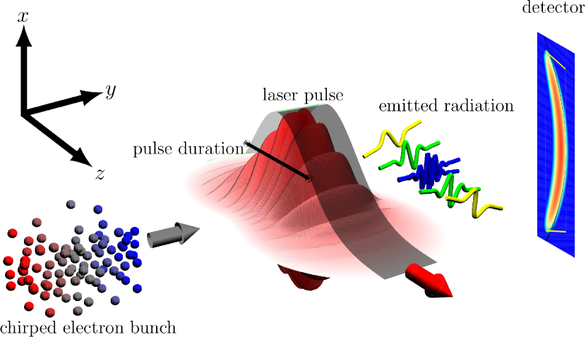
This Letter aims at filling this gap by proposing a fundamentally new approach to quantifying a laser pulse’s duration directly in focus at high field strengths. Its basic working principle is to imprint a temporal structure onto an electron bunch to be scattered from the intense laser pulse, in the form of an energy chirp as are common in laser-accelerated electron bunches and need to be mitigated with great effort Brinkmann_etal_2017 . Keeping the electron bunch chirped, the particles’ changing energy will lead to a temporal evolution of the angular range into which the electrons emit radiation. Here we quantify this temporal change by means of a simplified analytical model which is then benchmarked by numerical simulations, demonstrating that the pulse’s duration can be quantitatively inferred. In order to make the electrons’ radiation signal easily extractable from the laser’s focal region and to decouple it from the strong optical laser radiation background, it is favorable to let the electrons collide with the laser pulse perpendicularly. A conceptual visualization of the proposed pulse duration measurement scheme is presented in Fig. 1.
Theory - In the following, we analyze the emission from an electron bunch propagating along the -axis colliding perpendicularly with a laser pulse propagating along the positive -axis and polarized along the -axis (s. Fig. 1). In order to quantify the overall angular distribution of the bunch’s emitted radiation, we make use of the fact that at each time instant the radiation emitted by an ultra-relativistic electron is confined to a narrow cone around its instantaneous direction of propagation. Thus, we approximate the time-dependent direction into which radiation is emitted as the time-dependent electron propagation direction. In order to quantify the angular emission region, we thus need to solve the electrons’ equation of motion, which is generally involved in a laser field of arbitrary focusing. On the other hand, it was demonstrated previously that for schemes utilizing the emission of a laser-driven electron bunch as signal it is favorable to quantify the boundaries of the angular radiation distribution and measure these in an experiment, as they provide a clear detection signal Mackenroth_etal_2010 ; Har-Shemesh_etal_2012 . These extremal emission angles will be determined by the strongest electron deflection, i.e., at the regions of highest field strength. Consequently, we focus on the electron dynamics close to the laser’s focus, which we assume to lie in the plane in the following. In this focal region the laser field is well approximated by a plane wave, provided the transit time of the electrons through the focal volume is longer than the pulse duration , so that they will not experience non-plane wave field contributions far away from the laser focus. The ratio of these quantities, which has to exceed unity, can be found as , where is the laser’s spot radius and we assumed the electrons to propagate with the speed of light. We thus see that the plane wave approximation is valid only for not too tight focusing or short laser pulses. It will be demonstrated, however, that for FWHM pulse durations down to fs the analytical model provides good agreement with a full numerical simulation. We assume the above condition to be satisfied and consequently approximate the electrons’ dynamics by analytically known electron trajectories inside a plane wave with four-potential , with , the pulse’s polarization vector and temporal shape . We begin by analyzing the emission angles from an electron bunch with constant energy . We then quantify the direction into which the electrons emit radiation in terms of the spherical coordinate angles and , with respect to the -axis as polar axis and the -axis as azimuthal axis. As we are interested in the boundaries of the angular region into which the electrons emit radiation, we only consider the deflection of the electrons’ from their initial propagation direction with and where the electrons’ initial propagation direction in the considered setup is given by . The deflection angles are given by the inverse tangents of the following ratios of the electrons’ instantaneous momentum components , , where is the electron’s momentum perpendicular to the polar axis. From the analytically known expressions for an electron trajectory inside a plane wave Sarachik_Schappert_1970 ; Salamin_Faisal_1996 it can be derived that for the suggested perpendicular collision geometry these maximal deflection angles are given by
| (3a) | ||||
| (3b) | ||||
where the ambiguity in the sign of the azimuthal deflection indicates that for the chosen setup the electrons emit symmetrically into the halfspaces and , respectively. The polar deflection , on the other hand, in a plane wave is always pointed towards the laser’s propagation direction, resulting in . We thus see that in the - plane the emission is confined to a rectangular region . The advantage of analyzing this emission box rather than the angular range of only one of the angles is clearly that while the angle range in always depends on the ratio , in the regime the angle range in depends on the square of this ratio. Consequently, the emission box is sensitive to the electron dynamics in a broader parameter range than just one of the angles.
We now turn to including a temporal structure in the electron bunch’s energy distribution in the form of an energy chirp. Consequently, the ratio will change over time, imprinting information about the pulse’s temporal intensity evolution onto the temporally changing angular deflection. Naturally, as the electron bunch propagates perpendicularly to the laser pulse, there will be a different emission box for each point in space. However, we are only interested in the boundaries of the total emission box, originating from the point of strongest electron deflection. Inside a laser focus this occurs in the center of the laser focus. In our computations we chose the focus’ center to coincide with the coordinate origin , where we thus localize our analysis. We can then model the bunch electrons’ energy to be a function only of time, which we approximate as changing linearly according to , where we defined the scaled electron pulse duration with the bunch’s FWHM duration and its energy spread and all other definitions as before. The negative sign for the chirp term ensures the electrons’ energy to decrease over time, leading to an increase of the emission angles, avoiding the emission box’s boundaries to be covered by radiation emitted at earlier times. In this case of a chirped electron bunch, the maximal emission angles will be different from the values for an unchirped electron bunch. To quantify the dynamically changing boundaries of the emission box we repeat the above analysis but now include the time dependency of both the electrons’ energy as well as the laser’s intensity
| (4a) | ||||
| (4b) | ||||
where by we denote the time instant at which the maximum deflection occurs. In order to determine this time instant, we assume the laser pulse to have a Gaussian shape in time with the physical and scaled FWHM pulse durations and , respectively. To now find we neglect the field’s oscillatory structure, and compute the time at which Eqs. (4) are extremal. It turns out, that both angles reach their maxima at
| (5) |
We see that, due to the time dependence of the electrons’ energy, contrary to the naive guess, the maxima of the emission angles, will not be reached at the field’s maximum at , but instead increases for increasing pulse durations . Furthermore, we see that a maximum only exists provided . This condition indicates that for too long laser pulses the emission angles do not reach a maximum value but change monotonically over the whole interaction time. Consequently, as Eqs. (4,5) explicitly depend on , we can use the emission box’s boundaries to determine the laser’s pulse duration.
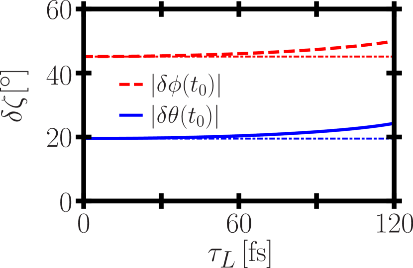
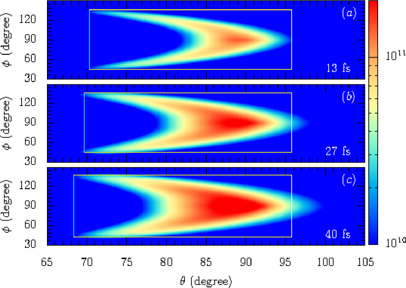
Results and Discussions - To quantitatively exemplify the dependency of the emission box’s boundary angles on we consider the interaction of a moderately relativistic electron bunch . We assume the bunch to have a large energy spread , as can be typical for an electron bunch from a laser-accelerator not optimized for monochromaticity Pak_etal_2010 ; Clayton_etal_2010 . The laser is assumed to have a dimensionless amplitude of at a central frequency eV. Plotting the resulting changes of the emission box’s cutoff angles (4) we find a clear dependence on the laser’s pulse duration (s. Fig. 2). Thus, determining the boundary angles of the emission box emitted by a chirped electron bunch scattering from a relativistically intense laser pulse allows to determine the pulse’s duration. To corroborate the above analytical conclusions, we performed a full numerical simulation of the above scattering with a realistic laser field and electron bunch. We used the paraxial Gaussian beam model Salamin2002 for a laser pulse of not too tight focusing to a spot size of m. The electron bunch is assumed to be composed of 300 particles distributed according to a Gaussian density distribution in its transversal dimension and uniform in longitudinal direction, with FWHM extensions of m in length and m in width. To compute the radiation signal emitted by this electron bunch colliding with the given laser pulse we numerically calculate the electrons’ trajectories by the relativistic Lorentz force equation of motion and calculate the resulting power radiated per unit solid angle through the standard Linart-Wiechert potentials Jackson ; Holkundkar_etal_2015 ; Harvey_etal_2016 . Superimposing the emission box according to Eqs. (4,5) over the numerically obtained radiation signal emitted by the specified electron bunch colliding with laser pulses of various durations we find an excellent reproduction of the numerically obtained emission box boundaries by the analytical prediction (s. Fig. 3). We thus conclude that these boundary angles of the emission box are defined by emissions close to the laser focus, where the employed plane wave model is a good approximation for the electron dynamics. We note, contrary to the analytical prediction, there occurs emission into angles , which we attribute to ponderomotive scattering from the laser focus, not accounted for in the model. To provide a qualitative estimate of this effect, we note that the ponderomotive push causes an additional angular deflection scaling as the ratio of the derivative of the electric field’s square to the transverse momentum. In the present case, we can thus estimate the ponderomotive scattering angle to be of the order . Shifting the emission box boundary from to in Fig. 3, we find this estimate approximately satisfied. For all other boundary angles of the emission box the ponderomotive effect is dominated by the electron dynamics and thus not observable. We conclude that detecting the emission box cutoff angles for and gives a reliable determination scheme for the laser’s pulse duration.
The proposed pulse duration scheme requires proper knowledge of the electron bunch parameters, such as its duration, energy spread, and central energy. These characteristics can most easily be obtained by spectroscopically recording the electron bunch after the interaction, when it is no longer needed. We have thus repeated the above numerical simulations including the energy loss of the electrons due to the emission of radiation in the form of radiation reaction, by replacing the Lorentz force equation by the Landau-Lifshitz equation for computing their dynamics LandauII ; Mackenroth_etal_2013 . We found the difference in the radiation signal to be negligible, whence the spectral bunch properties before and after interaction with the laser pulse are comparable, facilitating a post-scattering characterization of the electron bunch.
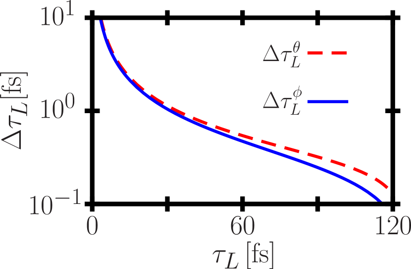
Finally, we wish to assess the accuracy for determining the pulse duration achievable through the proposed setup. In a real experiment the cutoff angles of the emission box can be detected only up to a certain accuracy. The scheme’s accuracy in determining the pulse duration, in turn, depends on the accuracy of the angle measurement. The error in the pulse duration measurement caused by an inaccuracy in the angle measurement can be derived through an error propagation to be with . From Eqs. (4a,4b) we find complex expressions for the derivatives which we do not need to report here. Evaluating these expressions for the above studied parameters and an assumed angular accuracy of we find the error of the pulse duration to be comparable for both and and to be negligible for pulse durations above fs (s. Fig. 4). Moreover we find the error to decrease for longer pulses, as for ever longer pulses a fixed change in leads to ever increasing changes in and .
Concluding Remarks - We have put forward a scheme capable of determining the duration of a laser pulse of in principle arbitrarily high intensity. It takes advantage of the fact that an the electromagnetic radiation emitted by electrons interacting with an intense laser pulse is angularly confined to an emission box depending solely on the ratio of the electron’s and laser’s local energy and field strength, respectively. Thus, we demonstrated that by imposing a temporal energy chirp onto the electron bunch it is possible to imprint information about the laser’s temporal structure onto the integrated emission signal. This information notably also contains a clear dependence on the pulse’s temporal duration, which can henceforth be measured. Assuming an angular detection accuracy of we have shown that the pulse duration can typically be determined with an accuracy of several percent for pulses longer than fs.
Acknowledgments - AH acknowledges the Science and Engineering Research Board, Department of Science and Technology, Government of India for funding the project EMR/2016/002675. AH also acknowledges the local hospitality and the travel support of the Max Planck Institute for the Physics of Complex Systems, Dresden, Germany.
References
- (1) A. Di Piazza, C. Mueller, K.Z. Hatsagortsyan and C.H. Keitel, Rev. Mod. Phys. 84, 1177 (2012).
- (2) G.A. Mourou, G. Korn, W. Sandner and J.L. Collier (editors), Extreme Light Infrastructure - Whitebook, (2011).
- (3) E. Esarey C.B. Schroeder and W.P. Leemans, Rev. Mod. Phys. 81, 1229 (2009).
- (4) K.T. Phuoc et al., Nature Photonics 6, 308 (2012).
- (5) G. Sarri et al., Phys. Rev. Lett. 113, 224801 (2014).
- (6) W.P. Leemans et al., AIP Conference Proceedings - Advanced Accelerator Concepts 1299, 3 (2010).
- (7) C. J. Hooker et al., J. Phys. IV 133, 673 (2006).
- (8) V. Yanovsky et al., Opt. Express 16, 2109 (2008).
- (9) Scottish Centre for the Application of Plasma-based Accelerators (SCAPA), http://www.scapa.ac.uk/?page_id=103.
- (10) Z. Major et al., The Review of Laser Engineering 37, 431 (2009).
- (11) J. P. Zou et al., High Power Laser Sci. Eng. 3, e2 (2015).
- (12) J. Kawanaka et al., J. Phys. Conf. Ser. 688, 012044 (2016).
- (13) T. Akagi et al., Phys. Rev. Spec. Top. Accel. Beams 19, 114701 (2016).
- (14) T. Wittmann et al., Nature Physics 5, 357 (2009).
- (15) A. Titov et al., Phys. Rev. D 93, 045010 (2016).
- (16) M.J.A. Jansen and C. Müller, Phys. Rev. D 93, 053011 (2016).
- (17) R. Trebino et al., Rev. Sci. Instrum. 68, 3277 (1997).
- (18) I. A. Walmsley and C. Dorrer, Adv. Opt. Photon. 1, 308 (2009).
- (19) R. M. G. M. Trines et al., Nature Physics 7, 87 (2011).
- (20) F. Eilenberger and A. Brown and S. Minardi and T. Pertsch, Opt. Express 21, 25968 (2013).
- (21) M. Bukshtab, Applied Photometry, Radiometry, and Measurements of Optical Losses, Springer Series in Optical Sciences (2012).
- (22) J.E. Decker, W. Xiong, F. Yergeau and S.L. Chin, Appl. Opt. 31, 1912 (1992).
- (23) E. Goulielmakis et al., Science 305 1267 (2004).
- (24) G.G. Paulus et al., Nature 414, 182 (2001).
- (25) G. G. Paulus et al., Phys. Rev. Lett. 91, 253004 (2003).
- (26) M. Kress et al., Nature Physics 2, 327 (2006).
- (27) D. Hoff et al., Nature Physics 13, 947 (2017).
- (28) O. Har-Shemesh and A. Di Piazza, Opt. Lett. 37, 1352 (2012).
- (29) G. Pariente, et al. Nature Photonics 10, 547 (2016).
- (30) M. Kübel et al., Phys. Rev. Lett. 119, 183201 (2017).
- (31) F. Mackenroth, A. Di Piazza and C.H. Keitel, Phys. Rev. Lett. 105 063903 (2010).
- (32) M. Wen et al., Phys. Rev. E 85, 035401 (2012).
- (33) W. Yan, et al. Nature Photonics 11, 514 (2017).
- (34) C. Harvey, T. Heinzl and A. Ilderton, Phys. Rev. A 79, 063407 (2009).
- (35) R. Brinkmann, et al., Phys. Rev. Lett. 118, 214801 (2017).
- (36) E.S. Sarachik and G.T. Schappert, Phys. Rev. D 1, 2738 (1970).
- (37) Y.I. Salamin and F.H.M. Faisal, Phys. Rev. A 54, 4383 (1996).
- (38) A. Pak et al., Phys. Rev. Lett. 104, 025003 (2010).
- (39) C.E. Clayton et al., Phys. Rev. Lett. 105, 105003 (2010).
- (40) Y. I. Salamin, G. R. Mocken, and C. H. Keitel, Phys. Rev. ST Accel. Beams 5, 101301 (2002).
- (41) J.D. Jackson, Classical electrodynamics, Wiley, New York (1999).
- (42) A.R. Holkundkar, C. Harvey and M. Marklund, Phys. Plasmas 22, 103103 (2015).
- (43) C. Harvey, M. Mattias and A.R. Holkundkar, Phys. Rev. Accel. Beams 19, 094701 (2016).
- (44) L.D. Landau and E.M. Lifshitz The Classical Theory of Fields, Pergamon Press (1971).
- (45) F. Mackenroth, N. Neitz and A. Di Piazza, Plasma Physics and Controlled Fusion 55, 124018 (2013).