High-Reflection Coatings for Gravitational-Wave Detectors: State of The Art and Future Developments
Abstract
We report on the optical, mechanical and structural characterization of the sputtered coating materials of Advanced LIGO, Advanced Virgo and KAGRA gravitational-waves detectors. We present the latest results of our research program aiming at decreasing coating thermal noise through doping, optimization of deposition parameters and post-deposition annealing. Finally, we propose sputtered Si3N4 as a candidate material for the mirrors of future detectors.
The high-reflecting (HR) coatings of the gravitational-wave (GW) detectors Advanced LIGO0264-9381-32-7-074001 , Advanced Virgo0264-9381-32-2-024001 and KAGRAPhysRevD.88.043007 have been deposited by the Laboratoire des Matériaux Avancés (LMA) in Lyon (Fr), where they have been the object of an extensive campaign of optical and mechanical characterization. In parallel, an intense research program is currently ongoing at the LMA, aiming at the development of low-thermal-noise optical coatings. The materials presented in this study are deposited by ion beam sputtering (IBS), using different coaters: a commercially available Veeco SPECTOR and the custom-developed DIBS and Grand Coater (GC). Unless specified otherwise, each coater uses different sets of parameters for the ion beam sources. Coating refractive index and thickness are measured by transmission spectrophotometry at LMA using fused silica substrates ( 1”, 6 mm thick) and by reflection spectroscopic ellipsometryPRATO20112877 at the OPTMATLAB using silicon substrates ( 2”, 1 mm thick). Results of the two techniques are in agreement within 3% and here are presented the average values, used to calculate coating density. Structural properties are probed by Raman scattering at the Institut Lumière Matière (ILM), using fused silica substrates. Finally, coating loss angle is measured on a Gentle Nodal Suspensiondoi:10.1063/1.3124800 ; PhysRevD.93.012007 (GeNS) system at LMA, with disk-shaped resonators of fused-silica ( 2” and 3” with flats, 1 mm thick) and of silicon ( 3”, 0.5 mm thick). is evaluated using the resonant methodnowick1972anelastic i.e. by measuring the ring-down time of several vibrational modes of each sample. For the -th mode, it writes
where is the loss angle of coated disk and is the loss angle of the substrate. is the so-called dilution factor which can be related to , , and PhysRevD.89.092004 , that are the frequencies and the mass of the sample before and after the coating deposition, respectively.
I Standard materials in gravitational-wave interferometers
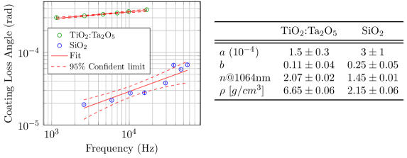
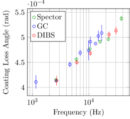
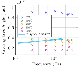
HR coatings of Advanced LIGO and Advanced Virgo are Bragg reflectors of alternate titania-doped tantala (TiO2:Ta2O5) and silica (SiO2) layers0264-9381-32-7-074001 ; 0264-9381-32-2-024001 . Fig. 1 shows the mechanical loss of these materials, which seems to follow a power-law function .
The loss angles of the HR coatings are shown on Fig. 2, together with their properties.
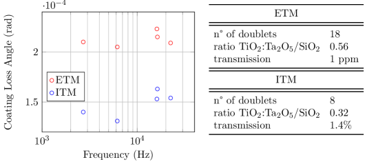
The end mirror (ETM) coating has higher loss angle than the input mirror (ITM) coating because of its higher ratio TiO2:Ta2O5/SiO2.
II Optimization
II.1 Doping
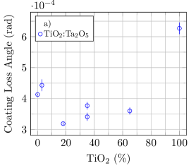
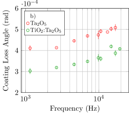
The purpose of TiO2 doping is to increase Ta2O5 refractive index and reduce its loss angle. Increasing the refractive index contrast in the HR stack would allow to decrease the HR coating thickness, at constant reflectivity. Fig. 3a shows Ta2O5 coating loss as function of doping. The current doping value in GW detectors is 18%, which yelds a minimum loss but a refractive index only slightly higher than that of Ta2O5. As shown by Fig. 3b, 18%-doped is lower than by 25%. Increasing TiO2 concentration will increase TiO2:Ta2O5 refractive index, while for TiO40% can not be predicted and needs further investigation.
II.2 Deposition parameters
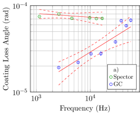
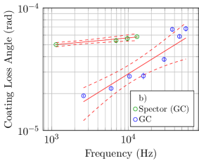
Fig. 4a shows coating loss of SiO2 deposited by GC and Spector using their respective standard deposition parameters. It is clear that by using different parameters the same material gets different properties: GC parameters yield lower coating loss. For further test, SiO2 has been deposited in the Spector with GC parameters. As Fig. 4b shows, Spector coating loss is lower but still higher than GC coating loss, because of the different configuration of the coaters.
Coating losses of Ta2O5 deposited using different coaters have different values before annealing but converge toward a common limit value after, as shown in Fig. 8, suggesting that annealing ’deletes’ the deposition history of the sample. Material properties are listed in table 1.
| SiO2 | Ta2O5 | ||||
|---|---|---|---|---|---|
| Spector | Spector as GC | GC | Spector | DIBS | |
II.3 Post-deposition annealing
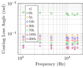
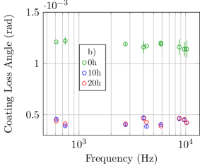
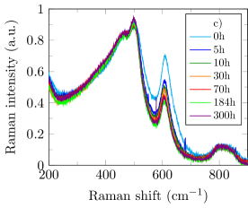
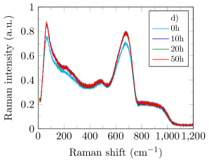
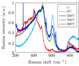
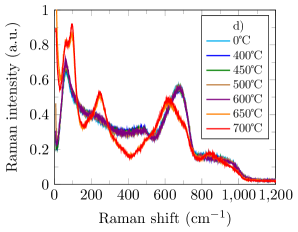
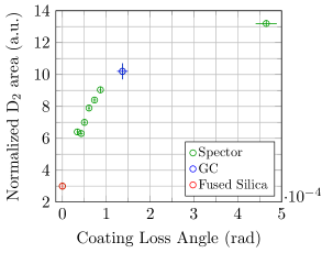
Annealing parameters are of fundamental importance for the purpose of reducing coating thermal noise. The problem is to find the optimal annealing temperature and duration , avoiding coating crystallization which would increase optical loss by scattering and absorption. In Fig. 5 is shown the effect of increasing with 500℃ constant. SiO2 loss decreases and this behaviour has a structural counterpart. SiO2 is composed of tetrahedral units arranged in rings of different sizePhysRevB.50.118 and the area of the D2 band near 600 is associated to 3-fold ring populationPhysRevLett.80.5145 . A correlation between coating loss and D2 has been found, suggesting that SiO2 loss increases with the 3-fold ring populationgranata2017correlated . This correlation holds for different kinds of SiO2, coating and bulk (Fig. 8). On the other hand, Ta2O5 loss does not change for 10h and its structure evolves only for 10h. Fig. 6 shows coating loss and structure for increasing , with 10h constant. SiO2 loss decreases and its structure evolves considerably. Surprisingly, crystallization occurs at 1000℃. For Ta2O5, coating loss is roughly constant for 500℃ and its structure does not change up to 600℃, when crystallization occurs.
III New material
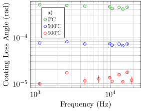
TiO2:Ta2O5 could be replaced by a material with lower mechanical loss and possibly higher refractive index. Here silicon nitride (Si3N4) is proposed, which features high refractive indexChao2017 and very low mechanical lossLiu2007 . Usually, Si3N4 is deposited by low pressure chemical vapour deposition (LPCVD). However, LPCVD Si3N4 might suffer from hydrogen contamination and thickness uniformity issues, which are not compatible with the stringent optical specifications required for GW detectors. Instead, IBS Si3N4 can be developed in the GC for deposition on large optics. Fig. 9 shows a comparison between TiO2:Ta2O5 and IBS Si3N4, this latter being annealed at different temperatures. Si3N4 loss decreases significantly at 900℃. Thus, one could increase the annealing temperature of the entire HR stack to decrease also SiO2 loss, eventually reducing the coating loss of the whole HR stack.
IV Conclusions
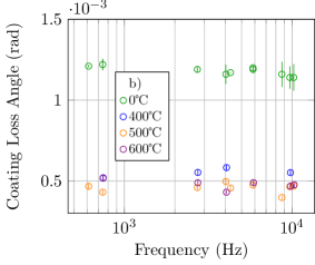
Coating materials of all present GW-detectors have been extensively characterized, showing a frequency-dependent loss angle. These standard materials can be optimized in different ways. The first approach is to increase the TiO2 content in TiO2:Ta2O5. Another option is to work on deposition parameters, in order to tune the optical and mechanical properties of the materials. In particular, the current GC configuration seems particularly well suited to deposit low loss SiO2. In the case of Ta2O5, the effect of different deposition parameters is erased by the first few hours of post-deposition annealing. For 400℃600℃ and 10h50h Ta2O5 loss shows null or limited evolution and its structure is frozen in a stable configuration. In the case of SiO2, the annealing parameters and have a significant impact on mechanical loss and coating structure. A correlation is found between D2 peak area in the Raman spectra, associated to the three fold ring population, and mechanical loss. IBS Si3N4 is an interesting new possibility to replace TiO2:Ta2O5 because of its low mechanical loss. Furthermore, Si3N4 can be annealed at higher temperature than TiO2:Ta2O5, reducing also SiO2 coating loss angle and thus the loss of the whole HR coating.
References
References
- (1) Aasi J et al. 2015 Classical and Quantum Gravity 32 074001.
- (2) Acernese F et al. 2015 Classical and Quantum Gravity 32 024001.
- (3) Aso Y, Michimura Y, Somiya K, Ando M, Miyakawa O, Sekiguchi T, Tatsumi D and Yamamoto H (The KAGRA Collaboration) 2013 Phys. Rev. D 88(4) 043007
- (4) Prato M, Chincarini A, Gemme G and Canepa M 2011 Thin Solid Films 519 2877 – 2880 ISSN 0040-6090 5th International Conference on Spectroscopic Ellipsometry (ICSE-V)
- (5) Cesarini E, Lorenzini M, Campagna E, Martelli F, Piergiovanni F, Vetrano F, Losurdo G and Cagnoli G 2009 Rev. Sci. Instrum. 80 053904.
- (6) Granata M et al. 2016 Phys. Rev. D 93(1) 012007.
- (7) Nowick A and Berry B 1972 Anelastic relaxation in crystalline solids (Academic Press)
- (8) Li T et al. 2014 Phys. Rev. D 89(9) 092004.
- (9) Granata M et al. 2017 arXiv preprint arXiv:1706.02928.
- (10) Jin W, Kalia R K, Vashishta P and Rino J P 1994 Phys. Rev. B 50(1) 118–131.
- (11) Pasquarello A and Car R 1998 Phys. Rev. Lett. 80(23) 5145–5147.
- (12) Chao S 2017 LIGO-G1700304.
- (13) Liu X, Metcalf T H, Wang Q and Photiadis D M 2007 MRS Proceedings 989.