Localization of transient gravitational wave sources: beyond triangulation
Abstract
Rapid, accurate localization of gravitational wave transient events has proved critical to successful electromagnetic followup. In previous papers we have shown that localization estimates can be obtained through triangulation based on timing information at the detector sites. In practice, detailed parameter estimation routines use additional information and provide better localization than is possible based on timing information alone. In this paper, we extend the timing based localization approximation to incorporate consistency of observed signals with two gravitational wave polarizations, and an astrophysically motivated distribution of sources. Both of these provide significant improvements to source localization, allowing many sources to be restricted to a single sky region, with an area 40% smaller than predicted by timing information alone. Furthermore, we show that the vast majority of sources will be reconstructed to be circularly polarized or, equivalently, indistinguishable from face-on.
1 Introduction
Numerous gravitational wave signals from binary mergers have now been observed [1, 2, 3, 4]. The sky location of these mergers have been provided with minimal delay, based on low latency gravitational wave (GW) searches [5, 6, 7] and rapid sky localization routines [8]. Subsequently, more detailed parameter estimation routines have provided updated localizations [9]. The rapid analysis and localization enabled the electromagnetic (EM) followup of all GW events and, most spectacularly, the observation of an EM counterpart to GW170817-GRB170817A [10] across the electromagnetic spectrum [11].
In [12, 13], it was argued that timing information provides a good estimate of the localization accuracy of a signal observed in a gravitational wave network. Nonetheless, the localization achieved by full parameter estimation analyses [8, 9, 14, 15] is significantly better than the timing approximation and makes use of the fact that the observed amplitudes and phases of the signal at different detectors must be correlated [8]. A detailed comparison of the results from timing-triangulation and full parameter estimation studies [16] demonstrated that there are important factors above and beyond timing which can improve the localization of sources. Here, we investigate the physical origin of these improvements and provide an intuitive explanation of the most important additional factors in localization. This is achieved by extending the localization calculation to incorporate correlations between the detectors, due to the fact that there are only two gravitational wave polarizations, and astrophysical priors on the source distributions. Inclusion of these effects leads to significant improvements in localization.
The fact that a gravitational wave is comprised of two polarizations guarantees the observed amplitude and phase of the signal at three or more detectors is correlated. Taking this into account improves the localization capabilities of the network. At sky locations other than the correct location, the requirement of signal consistency with two GW polarizations, reduces the reconstructed network signal-to-noise ratio (SNR) which improves the localization [17, 18]. For a three site network, timing triangulation gives two sky locations which are mirror images in the plane defined by the three detector locations. Including amplitude and phase consistency can, in principle, break this degeneracy and allow us to neglect one of the patches. In many cases, the recovered SNR at the mirror position will be of lower amplitude than the original, allowing us to reject the mirror position for around half of the sources.
Gravitational wave sources are expected to be distributed roughly uniformly in volume, at least at the sensitive distances of the advanced GW detectors — large enough to neglect local inhomogeneities and small enough that rate variations are not dominated by cosmological effects or the variation of the star formation rates during the evolution of the universe. Furthermore, the orientation of merging binaries is expected to be uniformly distributed. Consequently, the majority of sources will be observed close to face-on, as the strongest GW signal is emitted in this direction, and at large distances. In a three detector network, the signal at the mirror sky location will typically be reconstructed at a much smaller distance than the true signal, and oriented close to edge on, providing another method of rejecting the mirror sky location.
These effects also improve localization within a single sky patch. At positions offset from the true location, the observed SNRs will not be entirely consistent with a signal, allowing for improved localization. Additionally, the reconstructed orientation of the source will be increasingly edge-on and at a smaller distance as we move away from the true position. Incorporating amplitude and phase consistency between sites and imposing reasonable astrophysical priors on the source distribution allows us to localize the vast majority of sources to a single patch in the sky. In addition, the error region for most sources is more accurately identified by considering the localization of a circularly polarized signal. For a binary neutron star system observed in three detectors, the cumulative effect is to provide a factor of three improvement in localization over the timing triangulation results.
The majority of the paper deals with the three site advanced LIGO-Virgo network. However, we also consider future four and five detector networks incorporating LIGO India [19, 20] and KAGRA [21]. Sources observed in four or more detectors are localized to a single patch in the sky based on timing alone. Nonetheless, requiring a consistent signal between the sites and favoring distant, approximately face-on sources improves localization significantly.
The paper is laid out as follows. In section 2, we briefly recap the timing triangulation results and then present the extensions to a coherent analysis and the inclusion of astrophysical source distribution. In section 3, we provide the expected localizations for the advanced LIGO-Virgo network at design sensitivity as well as four and five detector networks incorporating KAGRA and LIGO India. Finally, in section 4 we provide a discussion of the results and indicate future directions of research. We provide two appendices: A which describes in detail the process of marginalizing over the astrophysical priors and B which gives a detailed derivation of the localization calculation.
2 Localization beyond triangulation
In this section, we present the new features which allow for improved localization. We begin with a brief review of the timing triangulation [12, 13], before extending the formalism to incorporate correlations between detectors due to a coherent analysis and the impact of astrophysically motivated priors on the source parameters, particularly location and orientation of binaries.
2.1 Timing
The accuracy with which the time of arrival of a gravitational wave can be measured in a single detector can be approximated as
| (1) |
where is the bandwidth of the signal in the detector and is the SNR [12]. The SNR is defined as
| (2) |
where is the template waveform, is the detector data,
| (3) |
and is the power spectral density (PSD). The bandwidth is given by
| (4) |
Defining as the time difference between the actual time of arrival in a detector and the recovered arrival time, we can obtain the probability distribution for which is proportional to the likelihood evaluated at those time offsets. Considering timing alone, the time delay distributions in each detector are independent and we obtain the distribution for the time-delay vector as,
| (5) |
This is converted to localization accuracy by re-expressing the relative time delays in terms of sky locations, as discussed in detail in [12, 13] and in B. We are ignoring the correlation of the arrival time with other parameters, such as the component masses of a binary merger. Since these correlations are similar in all detectors, they will have minimal effect on the measured time delay between sites, which is the important quantity for localization [12, 14].
2.2 Coherent Network Analysis
Since a gravitational wave signal is comprised of only two polarizations, with a network of three or more detectors there are consistency requirements between the observed SNRs in the detectors that comprise the network. As discussed in [22], we can express the network SNR as the projection of the individual detector SNRs onto the two-dimensional signal space, namely the two dimensional physical subspace of signals which is consistent with the two polarizations of gravitational waves.
To do so, we must first introduce the complex SNR Z. This is the output of the matched filter of a template waveform placed at some fiducial distance , with two orthogonal phases and , against the data ,
| (6) |
Then gives the SNR maximized over the signal amplitude and phase. The network SNR can be expressed as
| (7) |
where is a rank 2 projection matrix that projects the SNR onto the two gravitational wave polarizations and there is an implicit sum over and in (7). When the observed SNRs are consistent with a signal, . It is often convenient to work in the dominant polarization frame, where the network is maximally sensitive to the polarization,111Specifically, we choose a polarization angle that maximizes . It can be shown that as a consequence and is minimized. See e.g. [22, 23] for details. and the projection operator is then given by [22]
| (8) |
The quantities are the sensitivity weighted detector response functions, and are the well known detector response functions, see e.g. [24] for the definition.
Consider the situation where the template matches the signal in the detector data, apart from a time and phase offset, and neglect the effect of noise contributions. To calculate the SNR, we simply note that a time offset can be expressed in the frequency domain as and expand to second order in . Following [12], we have
| (9) |
Substituting this expansion into (7), we obtain an expression for the network SNR for a given set of time delays . The likelihood, maximized over the amplitude and phase of the signal in the two polarizations, is given by
| (10) |
as discussed in detail in A. The associated posterior probability distribution for is proportional to the likelihood so that
The first term is identical to the timing triangulation result (5), while the second term imposes amplitude and phase consistency between the sites. Indeed, the timing expression is recovered, as expected, by setting . We can intuitively understand the origin of the additional term as follows: when localizing using only time delays, we are free to maximize individually the amplitude and phase of the waveform in each of the detectors; in the coherent network analysis, we are restricted to waveforms consistent with two GW polarizations — any violation of this will cause a loss in SNR as power is removed from the signal space and deposited in the null space, , which, physically, is not expected to contain any GW power [25, 18].
The result (2.2) has been obtained under two significant approximations. First, we have kept terms only up to quadratic order in . This quadratic approximation is accurate for moderate or large SNRs as discussed in [12]. Second, we have neglected the fact that the detector response varies across the sky and just used the value at the actual signal location. This can be justified by considering a point offset from the true location by an angle . Since the antenna patterns are quadrupolar, the response will characteristically change at a rate . Meanwhile, the time offset at a detector will be where is the separation between detectors (on the order of 10s of ms). Therefore, the fractional fractional change in SNR will be , for a typical value of Hz. The effect on phasing is several times larger than the effect of the antenna response, so we ignore the latter it in the calculation that follows. For points on the sky where signals are poorly localized, in particular those close to the plane defined by the detectors, the changing antenna response can be important, although the localization will still be poor. The importance of the changing antenna response has been considered in detail in, e.g., [26, 17].
To get a sense of the expected improvement from coherent localization, it is useful to look at a simple example. Consider the situation where we have three detectors which are equally sensitive to a signal and that two detectors are sensitive to the polarization while the third is sensitive to . To a reasonable approximation, the two LIGO detectors are aligned, and consequently sensitive to one GW polarization while, for many sky locations, Virgo is sensitive to the other GW polarization. Thus, we assume (and ). In this case the projection matrix (where the row/column order is H, L, V) is given by
| (12) |
We are interested in the localization of a source, so we want to see how falls off as we move away from the true location. The geometry of the LIGO-Virgo network can be approximated by an isosceles triangle, with the LIGO detectors separated by ms and the light travel time between each LIGO site and Virgo around ms. First, consider recovering the source with time offsets , i.e. at a position offset from the true location along a line connecting the midpoint between the LIGO detectors to Virgo. Since and the second line of (2.2) vanishes and the localization matches the timing result. If, instead, we have with , i.e. offset from the true position along a line connecting the two LIGO detectors, then the probability distribution is
| (13) |
This leads to a characteristic width of , where , rather than . The improvement arises from the fact that the two LIGO detectors are required to observe the same polarization of GW and hence the same amplitude and phase. For the advanced LIGO detectors at design, , and for binary neutron star (BNS) signals. For this example, the localization area will be reduced by around .
2.3 Mirror Sky Locations
For a gravitational wave detector network comprising three detectors at different sites, localization based on timing will lead to two possible locations, one above and the other below the plane defined by the locations of the detectors. From timing information alone, it is not possible to distinguish the correct location from the mirror location. However, once we move to coherent localization, it is, in principle, possible to distinguish between these positions. In the mirror location, the observed amplitudes and phases of the signal will generally not be consistent with a gravitational wave signal comprising only two polarizations — a fraction of the power will be in the null stream [25], thereby reducing the network SNR and allowing us to reject the mirror position.
At the mirror sky location, the measured network SNR will be
| (14) |
where is the complex SNR in detector and is the projection onto the signal space appropriate for for the mirror position. Typically, the observed SNRs will not be consistent with the mirror location so .222When the observed SNRs in the detectors at the mirror location are not consistent with a gravitational wave, a nearby sky location may give a larger network SNR even though the SNRs in the single detectors will be lower. This is discussed in detail in B. In the following discussion, we use to denote the maximum SNR near the mirror location.
There are two peaks in the sky location distribution — one at the true location and the other at the mirror location. However, since the SNR associated to the mirror location is smaller than at the correct location, the peak will be lower and this may allow us to reject it. To identify a confidence region containing a fraction of the posterior, we typically find the minimum area that contains the required probability. Equivalently, start with the peak of the distribution and add points with the highest available probability until we have incorporated the appropriate fraction of the probability. Thus, if the second peak is low enough, it will not be included in the confidence region.
In many cases, the width of the localization distribution, obtained from (2.2), at the true and mirror locations is comparable. If we assume that to be the case, then the probability distribution is well approximated by two 2-dimensional Gaussian distributions of equal widths, and the relative height of the second peak is given by
| (15) |
Then, the second peak will not appear in the localization area provided a fraction of the total probability lies in the first region, with a likelihood greater than the second peak, i.e
| (16) |
Here, the left hand side is the integrated probability in the first peak down to the level of the second peak; the right hand side is a times the total integrated probability. Thus, if
| (17) |
the source will be localized to a single sky patch.
To obtain a single sky patch at 90% confidence requires . For a signal at SNR of 12, this equates to a difference in SNR of 0.25 or greater between the true and mirror position. At 50% confidence, this reduces to or a difference in SNR of less than 0.1. For the advanced LIGO-Virgo detector network at design, about 60% of sources are localized to a single patch at 90% confidence based on this criterion.
2.4 Distribution of Sources
Gravitational wave events from binary mergers are reasonably assumed to be uniformly distributed in volume, at least at distances on the scale of hundreds of mega parsecs.333For smaller distances, the discrete structure of galaxies in the nearby universe will affect the distribution [27] while at larger distances, cosmological evolution and the variation of the merger rate with redshift have to be taken into account [28]. Binary mergers are also expected to be uniformly distributed in source orientation. So far, we have not taken these factors into account when calculating the localization areas. The expression in equation (7) is the maximized SNR — with maximization performed over the amplitude and phase of the two GW polarizations or, equivalently, the distance to and orientation of the binary. In recovering estimates of parameters, it is typical to marginalize (rather than maximize) over any unwanted, or nuisance, parameters. This can have a significant impact upon the localization results.
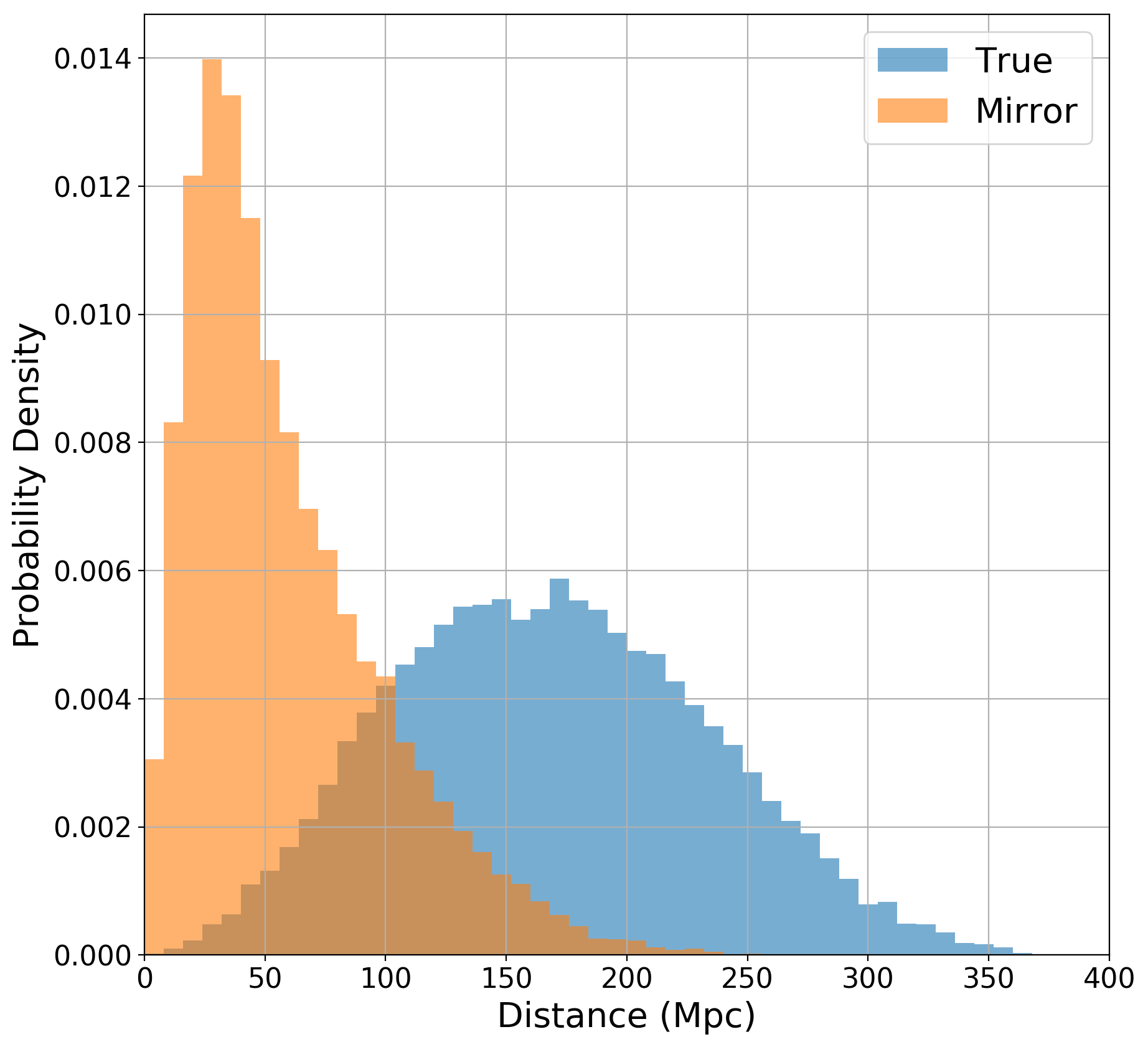
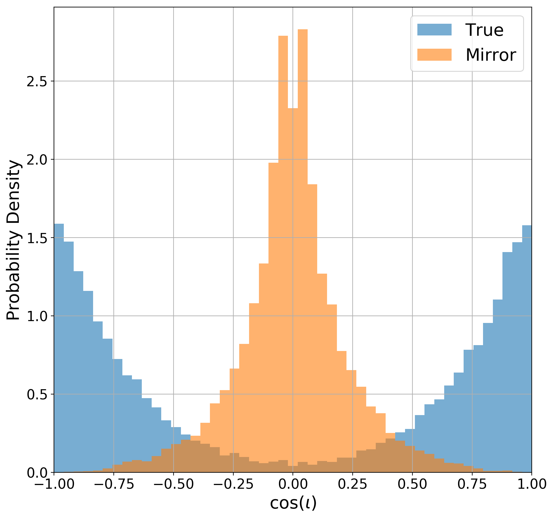
First, consider our ability to exclude the mirror location. For a given sky location, the observed SNRs and detector sensitivities encoded in can be used to infer the distance to, and orientation of, the source. The distribution of inferred distances for a population of BNS signals that might be observed by the Advanced LIGO-Virgo network operating at design sensitivity is shown in figure 1. This is obtained by generating sources uniform in volume and binary orientation and declaring an event to be observed if the expected network SNR is greater than 12 and the SNR in at least two detectors is greater than 5. The distributions for the correct and mirror locations differ significantly, with the true distance distribution peaking around Mpc and the majority of sources close to face-on. For the mirror location, the inferred distances are, on average, a factor of three smaller, and the majority of sources are recovered edge on.
Initially, let us only consider the distance. The fractional uncertainty in the distance measurement is inversely proportional to the observed SNR, i.e.
| (18) |
Assuming that signals are uniformly distributed in volume, the likelihood of observing a signal at a distance is proportional to . Thus, a simple marginalization over the distance leads to a re-weighting of the likelihood as
| (19) |
Then, following a similar argument to the one presented in section 2.3, it follows that if the inferred distance at the mirror sky location is a factor of lower than the true location, then it will be excluded from the 90% localization, even if the maximized likelihood is identical.444In addition, signals are statistically more likely to come from regions with greater sensitivity and, consequently, on average, the mirror location will be less sensitive. Thus, simply weighting the two positions based on the detectors’ sensitivity can increase the fraction of sources localized to a single region. However, this is only a minor effect. A simple distance-based scaling of the likelihood, combined with the reduced SNR at the mirror location discussed in section 2.2, increases the fraction of sources localized to a single patch with 90% confidence from 60% to 75%.
2.5 Face-on sources
Assuming reasonable parameter priors can also improve the localization accuracy for a single sky location. To illustrate this, consider again a network with three detectors equally sensitive to a given source, with two (H and L) sensitive to the polarization and the third (V) to , so that . In addition, assume that the source is face-on, so that the observed gravitational wave is circularly polarized and . If the source is reconstructed at a sky location corresponding to time offsets then, it follows from (9) that, the recovered phase in the H and L detectors will be while in it will be .
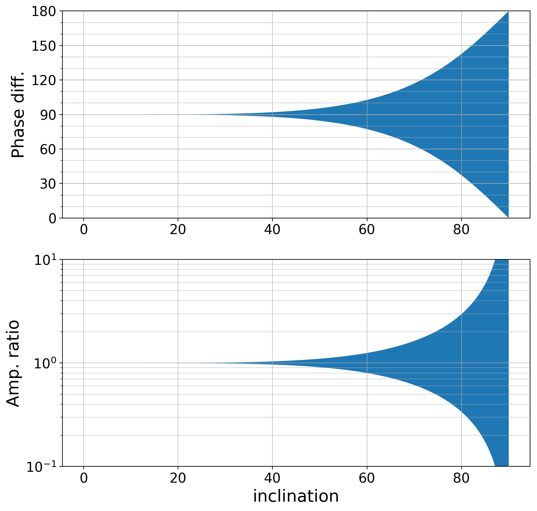
In figure 2 we show the range of possible phase and amplitude differences between the observed and polarizations as a function of the binary inclination. For edge on binaries, the emitted GW is linearly polarized so, depending upon the polarization angle, any amplitude ratio and phase difference is possible between and . For face-on signals, the waveform is circularly polarized so the phase difference is required to be , with equal signal amplitude in the two polarizations. For sources close to face-on, the amplitudes of the two polarizations must be similar and the phase difference close to . Interestingly, the inclination must be large before any significant difference from the face-on case is visible. In particular, a phase difference or amplitude difference is only possible if the binary inclination is greater than .
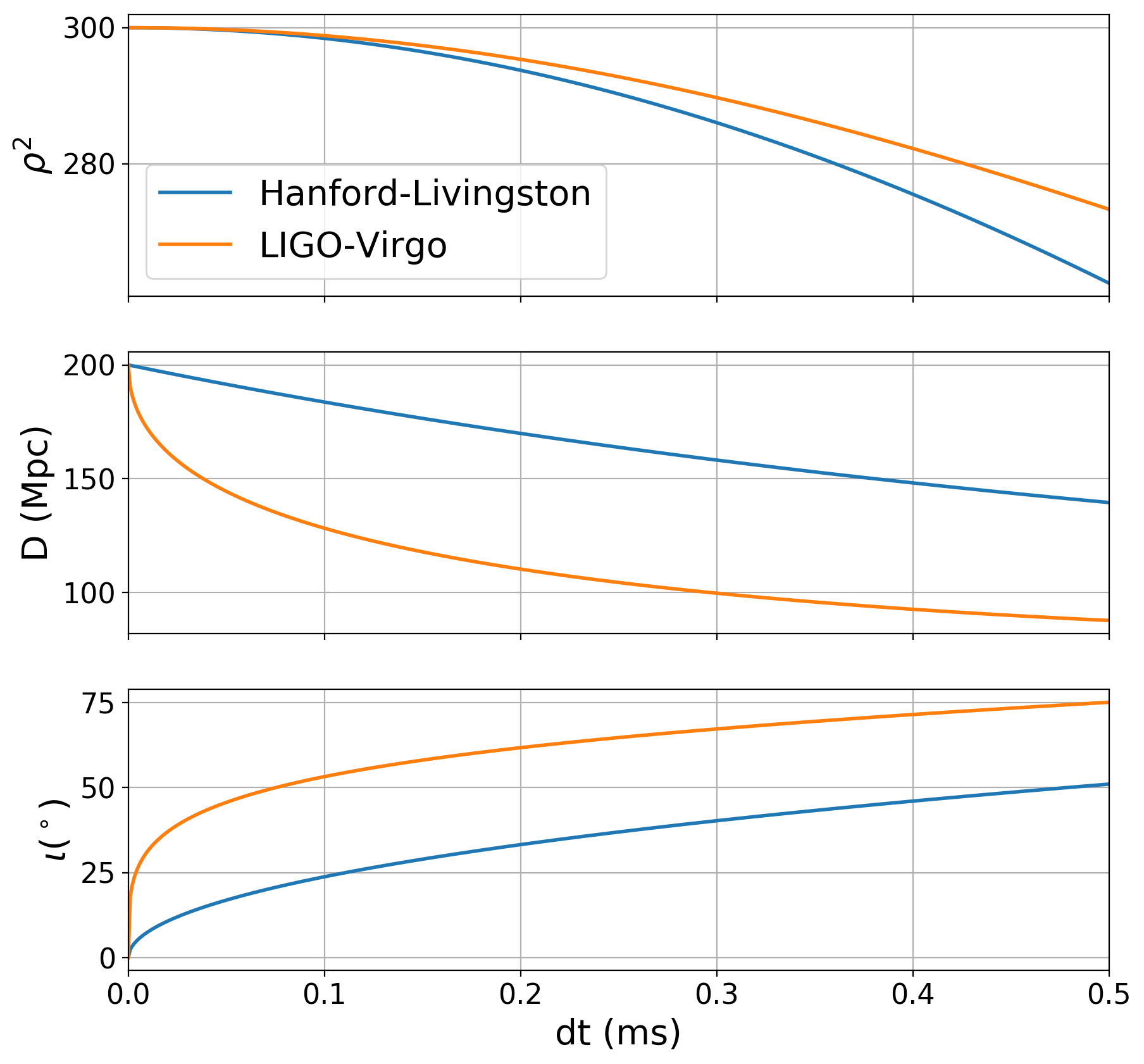
In figure 3, we show the maximized SNR as a function of the timing offset between the true and reconstructed location, as well as the inferred distance and inclination. This is plotted for both an offset between the two LIGO sites, and an offset between LIGO and Virgo. As expected from section 2.2, the SNR falls of more rapidly with a timing error between the two LIGO sites, as they are sensitive to the same polarization. For changes in the time delay between the LIGO sites, the source is recovered at a slightly reduced distance and not exactly face-on. The inferred amplitude of GW in the polarization will be slightly reduced due to the phase offset between the signal in the two LIGO detectors. For changes in the LIGO-Virgo time delay, the maximum SNR corresponds to a signal which is significantly closer than the true source and highly inclined. Already with a ms offset the reconstructed distance is reduced by and the reconstructed inclination is . As discussed in section 2.4, a lower inferred distance reduces the likelihood and this serves to improve localization.
2.6 Astrophysical Priors
To provide a more accurate assessment of the impact of distance and orientation priors on the source reconstruction, we need to calculate the likelihood marginalized over these degrees of freedom. As discussed in section 2.4, this will give higher weight to sources at a greater distances. It will also give higher weight to sources which are close to face-on or face-off, as the observed waveform varies only slowly with inclination, and the polarization and phase of the signal are degenerate for face-on sources.
In A, we derive an expression for the approximate marginalized likelihood of a signal based on the observed complex SNRs and detector sensitivities encoded in . The marginalized likelihood can be approximated by two contributions. The first is simply the area of the peak around the maximum likelihood [29, 30]. However, when the binary is close to circularly polarized, this does not give a good approximation to the marginalized result as there is a significant volume of parameter space associated with approximately face-on binaries, for which the waveform is circularly polarized, that provides a large contribution to the likelihood. Thus, we incorporate a second contribution based on the likelihood for approximately circularly polarized waveforms. The total marginalized likelihood is the sum of these two contributions.
To illustrate the result, we return to the example discussed previously, namely a network of three detectors equally sensitive to the signal, all observing with SNR 10. We vary the inclination angle of the source, while keeping the network SNR fixed, and calculate the marginalized likelihood. To make a connection with the previous results, we re-express the marginalized likelihood in terms of a re-weighted SNR as [7]
| (20) |
where is the marginalized likelihood for a source with inclination , and is the greatest value of the marginalized likelihood. This allows us to equate an unfavorable orientation with and effective reduction of SNR.
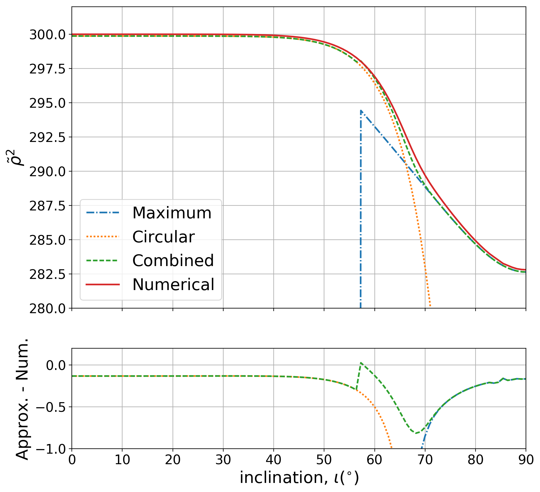
In figure 4 we show the re-weighted SNR computed both numerically and with the approximation based on maximum likelihood and circular polarized signals described above. For face-on, or close to face-on signals, the re-weighted SNR is unchanged. These are the signals which are consistent with the largest volume of parameter space. For edge on systems, reduces by almost 20, which is equivalent to reducing the SNR in each detector from 10 to 9.7. Equivalently, the chance of observing a face-on system is over a thousand times higher than an edge on system.
For each binary, we can evaluate whether the likelihood is predominantly accumulated around the maximum SNR or is associated with circularly polarized emission. If it is the former, then the coherent localization presented in section 2.2 is appropriate. However, if the likelihood is dominated by circularly polarized signals, the localization can be improved by imposing this restriction. To do so, we use the previous localization results but now project onto the space of circularly polarized signals using
| (21) |
where the signs give the left and right circular polarizations, respectively. This, in effect, restricts the signal to a single, overall free phase, as conjectured in [16]. In the space of time-delays, there is now a single direction — the one that leaves the relative phase between all pairs of detectors unchanged — where the localization is the same as the timing result. For all other directions, the localization width is .
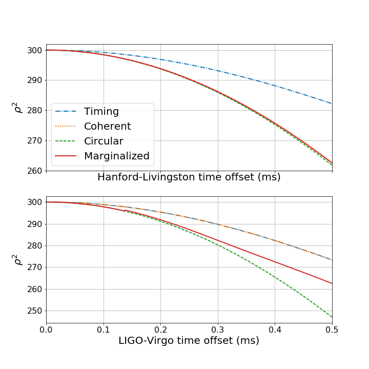
To demonstrate the utility of this approximation, figure 5 shows the falloff of the SNR under the timing, coherent and circular polarization approximations and compares these to the re-weighted SNR obtained from incorporating astrophysical priors and marginalizing over the likelihood. For a relative time delay between the two LIGO detectors, the coherent and circular polarized results are essentially identical, and match the re-weighted SNR result. Using timing only leads to a slower falloff of SNR and consequently poorer localization. For an offset between LIGO and Virgo, the timing and coherent results are identical, as Virgo is sensitive to a different polarization. Restricting to circular polarization causes the SNR to fall off more quickly, and provides a good match to the re-weighted SNR, at least for time offsets ms. For larger time offsets, the re-weighted SNR falls off more slowly, as at these locations the signal is no longer well approximated as circularly polarized. We note, however, that the source localization is determined by points with and in this region the circular polarization approximation works well.
3 Localization Results
3.1 Advanced LIGO-Virgo network
A realistic scenario for the evolution of the advanced LIGO and Virgo detectors towards their design sensitivities, and the expected localization of sources is given in [31]. We will not reproduce the full observing scenario here, but instead present results for the advanced LIGO-Virgo network operating at design sensitivity: advanced LIGO with a sky averaged sensitivity to BNS mergers of 200 Mpc, mean frequency of 100 Hz and bandwidth of 120 Hz; Virgo with a sensitivity of 130 Mpc, mean frequency of 130 Hz and bandwidth of 150 Hz. In addition, we assume that all detectors have an 80% duty cycle and that the times they operate are independent.
As with previous studies [12, 13, 14], we distribute sources uniformly in volume and binary orientation and deem sources detectable if the expected network SNR is above 12 with an SNR above 5 in at least two detectors. Furthermore, we assume that a detector will contribute to localization provided the SNR in that detector is greater than 4, and neglect entirely contributions from detectors with SNR less than 4. For each source that can be localized by three detectors, we calculate the localization area. We do this by first calculating the marginalized likelihood, as discussed in section 2.6 and presented in detail in A. For sources which are essentially face-on, we compute the localization from (2.2) by first restricting attention to circularly polarized signals using (21). When the signal is not circularly polarized, we project onto the coherent signal space with (8) when calculating the localization. We repeat the calculation for the mirror sky location and combine the distributions from the two locations as discussed in section 2.3. The procedure for going from a timing distribution (2.2) to an area is presented in B.
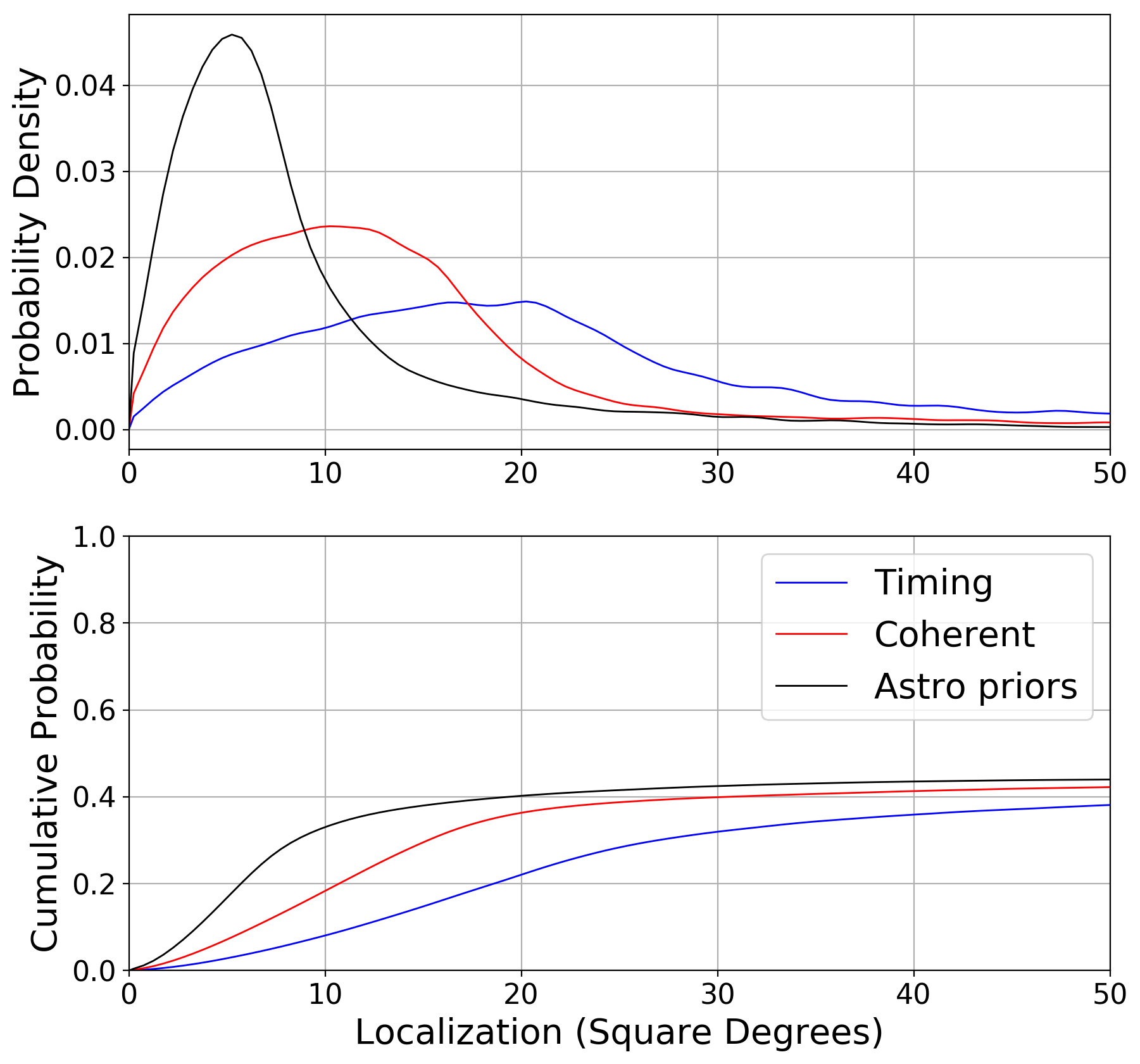
In figure 6, we show the distribution of localization areas for found events, using the three methods described in section 2: timing only, coherent analysis and a coherent analysis incorporating astrophysically motivated priors. We show both the distribution of areas and the fractional improvements for each event. The mode of the sky area distribution is reduced from for timing to for coherent analysis and when we incorporate the expected astrophysical distribution. In all cases only around 40% of sources are localized within . The majority of events which are not well localized are seen in only two detectors, either because only 2-detectors are operating due to the assumed duty cycle (about 25%) or the event does not have sufficient SNR in one detector for it to contribute to localization (about 25%) with the final 10% seen with sufficient SNR in all detectors to be localized, but just having poor localization.
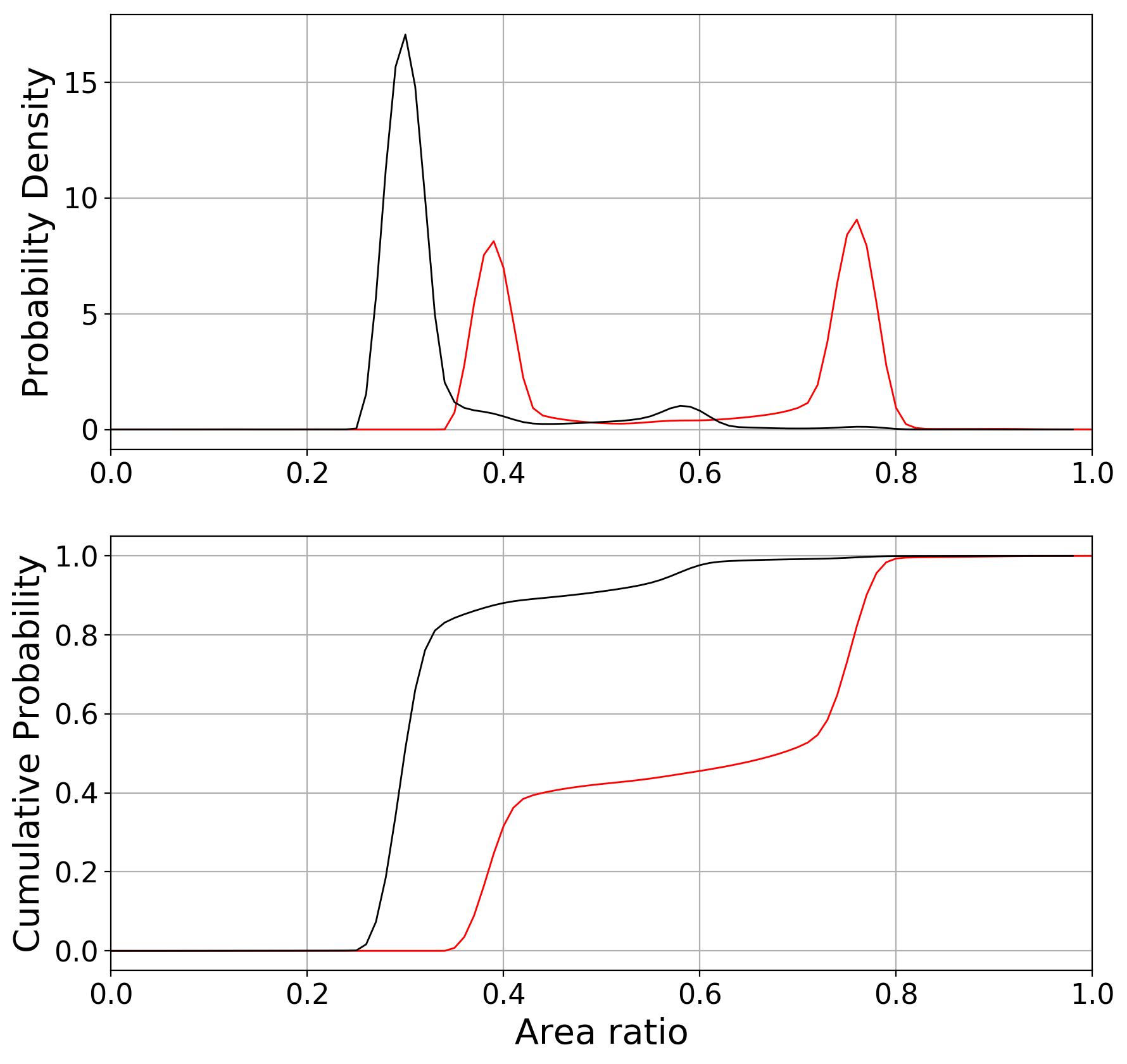
The second panel in figure 6 shows the ratio of the coherent or marginalized area to the value obtained with timing triangulation alone on an event-by-event basis. This shows two clear peaks for coherent localization. The peak at around 0.4 corresponds to events which can be localized to a single sky patch using coherent localization, while the second peak at around 0.75 includes those events which still give two sky patches. In both cases, there is a 25% reduction in the area of the sky region due to the requirement of amplitude and phase consistency across the three detectors. By incorporating astrophysical priors, the localization area for the majority of events is reduced to 30% of its original value. This corresponds to events which are localized in a single sky patch and are effectively face-on. The other, smaller peaks can be explained in a similar way: events with 40% of the original area are localized to a single patch, but not face-on; events at 60% are effectively face-on but from two sky regions; events at 75% are not face-on and come from two sky regions.
Finally, we note that in the above plots, we never assume that a source can be localized to a single sky location for the timing results. This is in contrast to the original work [12, 13] which gave timing areas under the assumption that sources would be localized to a single sky patch based on amplitude information. Thus, the distributions for timing-based localization above give twice the area as those presented in e.g. [12, 13]. The coherent localization results presented here are comparable to the timing results in the original papers. However, for each source, the localization is either 25% better due to coherent localization or 50% worse as the event is localized to two sky patches. When we incorporate astrophysical priors, the average localization is 40% smaller than the single patch timing triangulation result.
3.2 Networks of four and five detectors
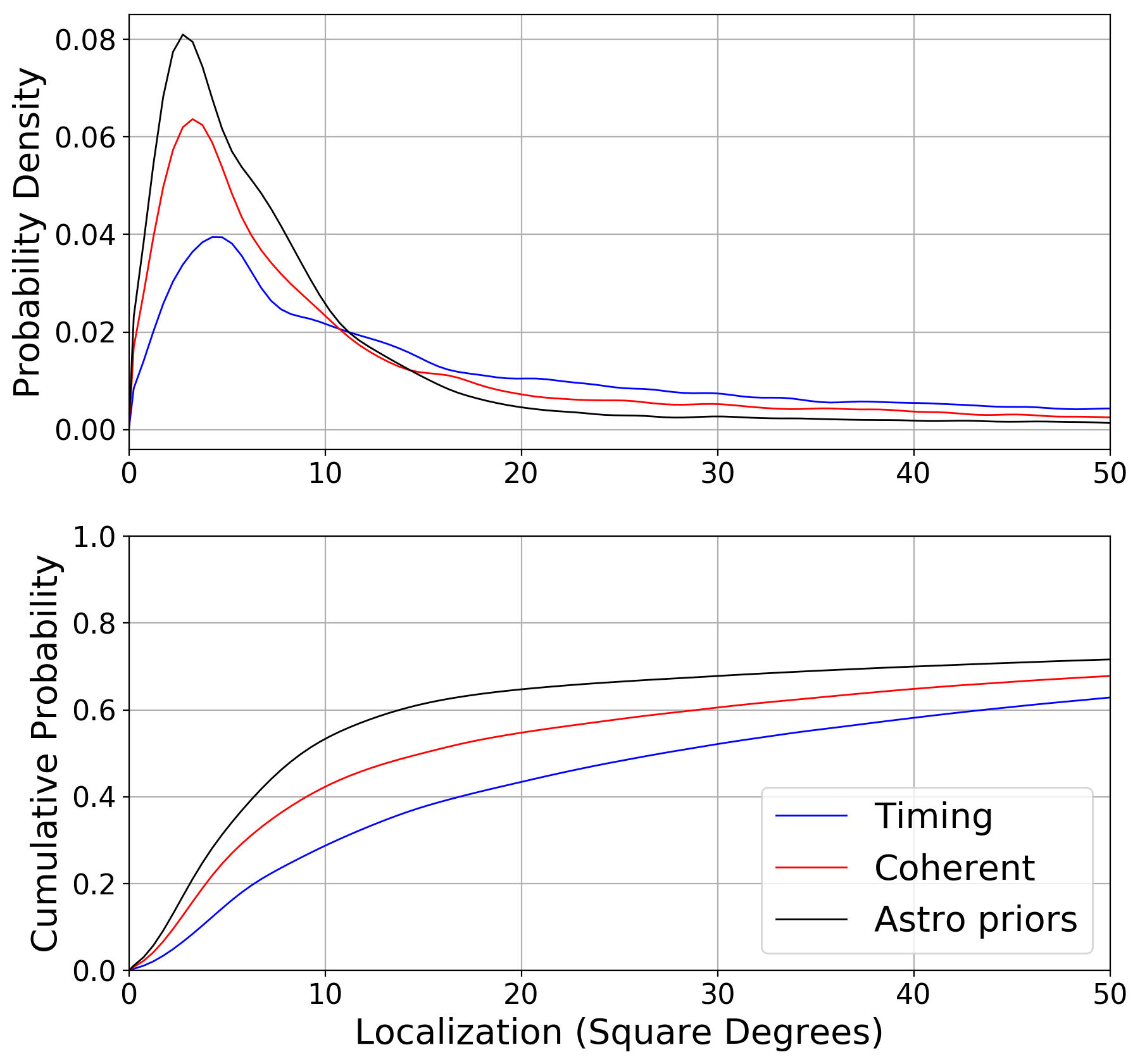
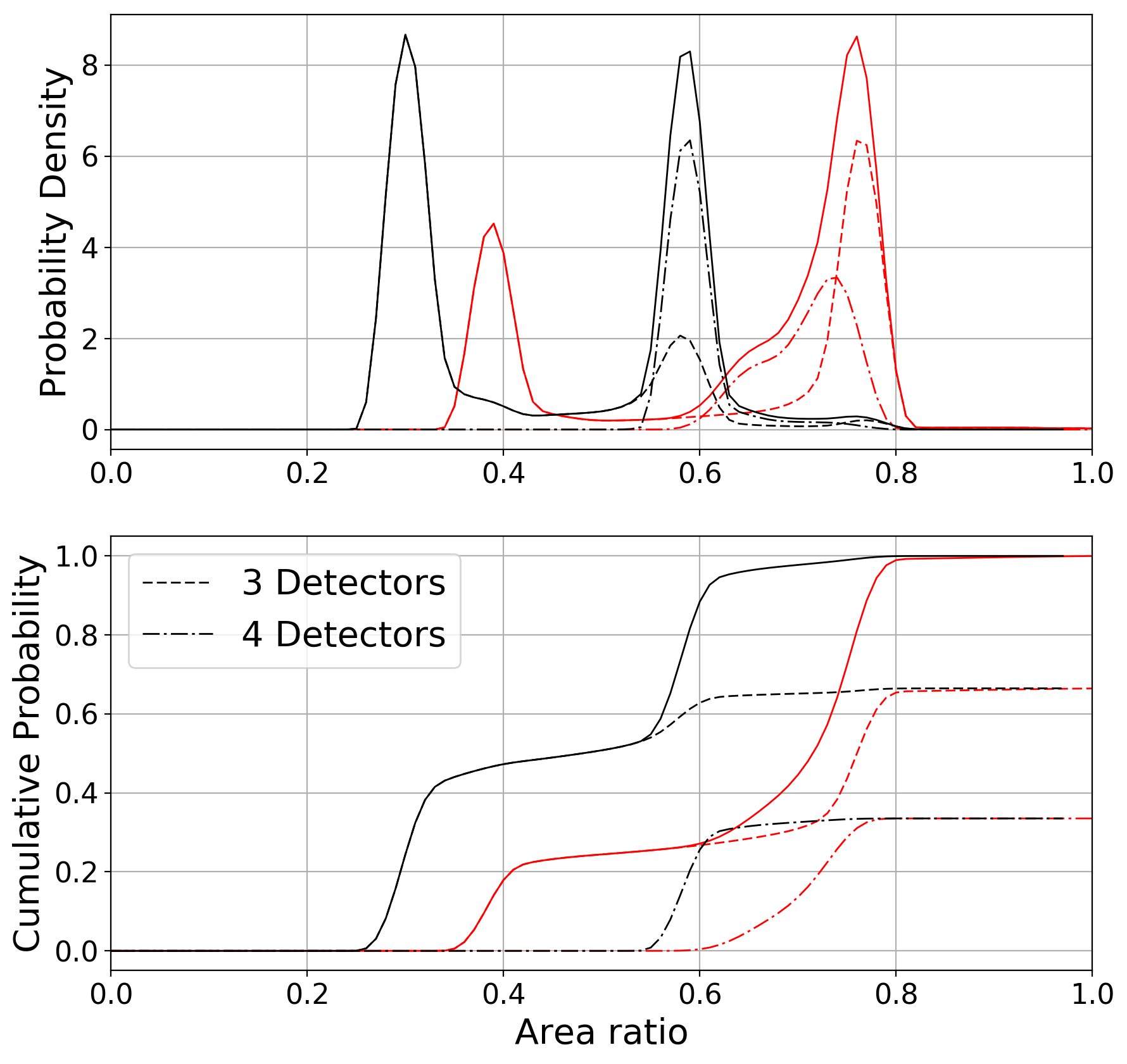
The longer term plan calls for a global network of five detectors, with the addition of KAGRA and LIGO India [21, 19, 31]. The analysis above can easily be extended to these networks. Sky location degeneracy is not a problem with four or more detectors — a unique sky patch can be determined from the time delays observed between four detectors. However, we can still require consistency with two gravitational wave polarizations, and incorporate astrophysical priors to improve the localization.
In figure 7 we show the expected localizations for events observed by the Advanced LIGO-Virgo network, where we assume that Advanced LIGO incorporates three detectors, with one in India. As before, we show the localization distribution as well as the event-by-event improvement of localization. The mode of the localization distribution decreases from for timing triangulation to for coherent and when astrophysical priors are incorporated. Around of found events are localized within , with the remainder either observed when only two detectors were operational (), only seen in two detectors () or observed in three detectors and poorly localized (). Of the events which are well localized, one third are observed in four detectors, due to live time and SNR thresholds, with the remainder observed in three. Since events observed in four detectors are localized to a single sky patch based on timing alone, the majority of these events see a reduction in area from coherent localization and a reduction when we incorporate an appropriate astrophysical distribution. The fact that coherent localization has a bigger impact for events observed in four detectors ( improvement rather than with three detectors) is expected as this leads to a reduction from four data streams, rather than three, to the two GW polarizations.
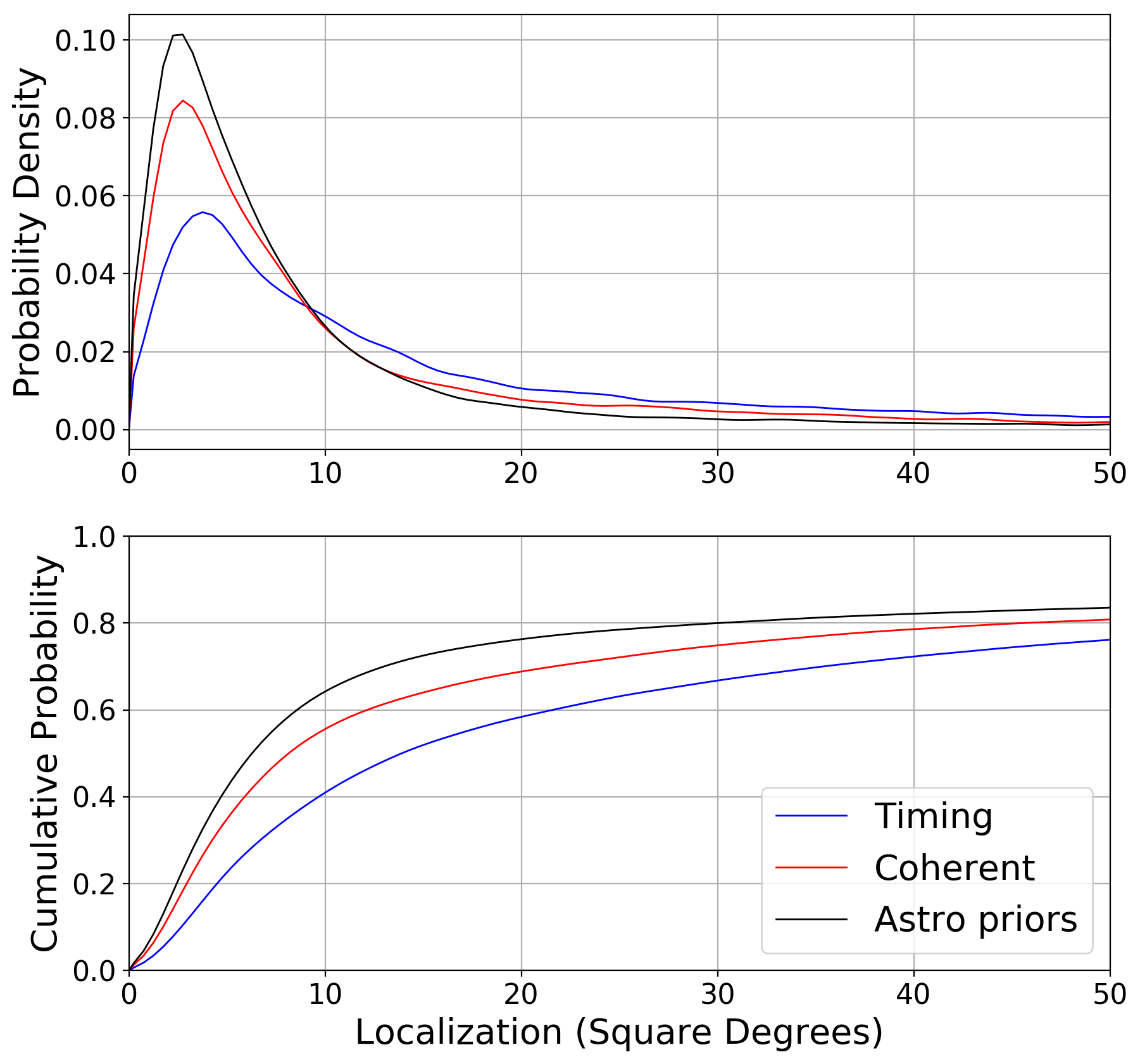
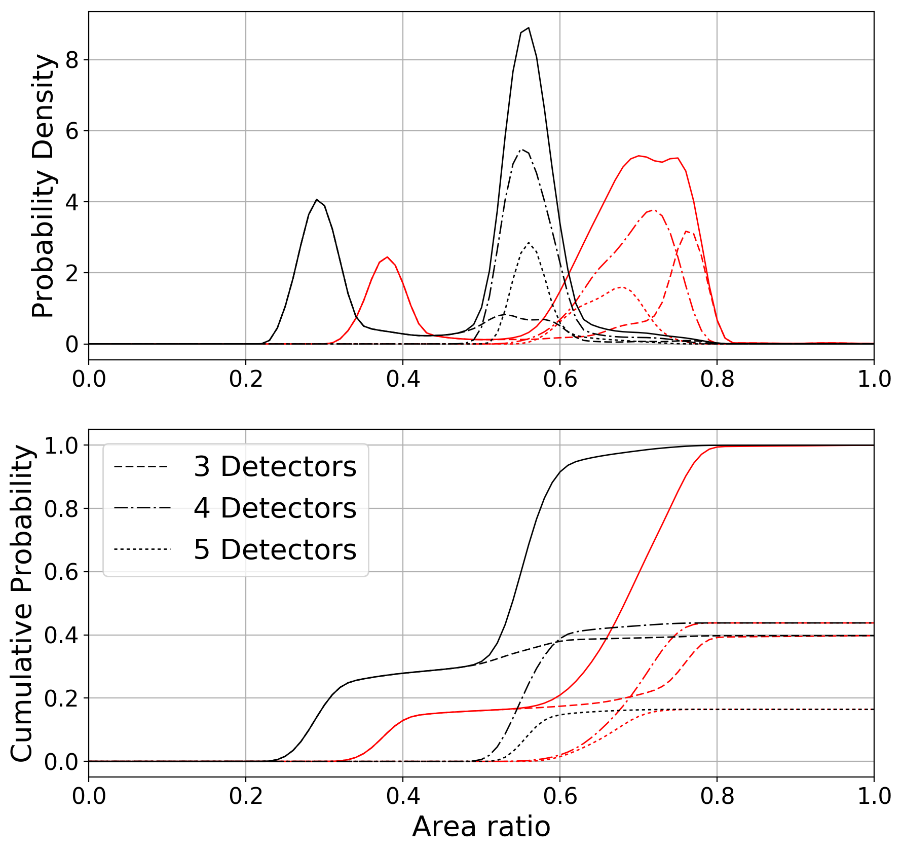
In figure 8 we show the expected localizations for events observed by the Advanced LIGO-Virgo-KAGRA network, where we assume that Advanced LIGO incorporates three detectors, with one in India. The results are similar to the four-detector network, with the mode of the area distribution decreasing from for timing triangulation to for coherent and when astrophysical priors are incorporated. Around 80% of observed events are localized within with of those not localized observed when only two detectors are operational; observed in only two detectors and localized more poorly than . For the 5-detector network, around 20% of well-localized events are seen in all five detectors, with 40% in four and the remaining 40% in three. Qualitatively, the 5-detector events are similar to those seen in 4-detectors: they are already localized to a single sky patch so coherent localization serves to reduce the area by , where again the localization improvement is better than with 3 or 4 detectors from consistency with two GW polarizations. For events seem in four or five detectors, inclusion of astrophysical priors reduces the area by between and .
4 Discussion
In this paper, we have examined in detail two effects that improve source localization over and above what is achieved with the timing triangulation approximation. The first is the requirement of a coherent signal, comprised of two gravitational wave polarizations, observed consistently in all detectors in the network. The second is the incorporation of an astrophysically motivated distribution of events, which are used as priors in the distance and orientation distributions, and lead to the expectation that the majority of observed signals will be distant and close to face-on. Both of these lead to considerable improvements in localization over timing, in the ability to restrict signals to a single sky patch and also to reduce the area of the sky patch. In previous timing triangulation studies, we assumed that sources could be localized to a single sky patch using additional information. Here, we have justified that assumption by showing that the vast majority, over , of sources will be localized to a single sky patch. Furthermore, the area of the sky region will be around smaller than predicted using timing information alone. Finally, we note that the improvement in localization is not uniform for all events — it varies depending upon whether events can, indeed, be localized to a single region and also whether they are recovered as circularly polarized.
In [16] a detailed comparison between timing triangulation and full parameter estimation localization was performed. The results presented here help to explain the discrepancies observed. In a future work, we plan to repeat the detailed comparison with full localization to verify that the new formalism provides a better approximation to the full results, and identify cases where the approximations introduced here are inadequate to capture the full parameter recovery results.
In this paper, we have not considered the localization of events observed in only two detectors. When only two detectors are operating, timing triangulation can only give localization to a ring on the sky. The coherent analysis does not improve this — the observed signal is consistent with a binary at a given distance and orientation at every sky point in the ring [32]. However, for many of these points, the binary will be inferred to be nearby and close to edge-on. By incorporating the astrophysical priors, those points are rejected [33, 34, 8]. In addition, even when three detectors are operating, a reasonable fraction of events will be observed in only two of them. As demonstrated by the observation of GW170817 [4], the lack of a clear signal in one detector can serve to significantly reduce the localization uncertainty of the event, as the source can be restricted to originate from a location close to one of the dead spots for the that detector. The techniques presented here can be extended to the case where two detectors observe a signal, and we will investigate localization with two detectors in a future work.
The analysis presented here is not intended to replace the detailed parameter estimation and localization techniques [8, 9, 15, 35] as it still makes use of a number of approximations. Nonetheless there are useful applications of an approximate method. The calculation of the localization is computationally straightforward, which allows for extensive studies to be run in a straightforward manner. This may identify regions of parameter space which are interesting for more detailed follow-up studies. The method presented here also provides some intuition into the key factors contributing to localization and provides a simple sanity check to the results obtained from complex analysis pipelines. The insights obtained from a simple understanding can also be used to inform development of detailed analyses. For example, it may be possible to adapt the jump proposals in an MCMC routine to follow the observed degeneracies in the approximations presented here [36]. Alternatively, the approximate likelihood is a natural candidate for the network detection statistic in an analysis pipeline as it naturally folds in the astrophysical weighting of the signal. Indeed, the improved detection statistic presented in [7] was independently motivated by investigations of calculating the marginalized likelihood for two detector observations.
Another application of this analysis is the study of calibration accuracy requirements for current and future detectors. In [12] we investigated the impact of calibration uncertainty on timing-based localization. It would be relatively straightforward to repeat that analysis using the improved localization techniques discussed in this paper. As an example, figure 2 makes it clear that for approximately face-on sources the amplitude of the two gravitational wave polarizations must be nearly equal and the phase difference essentially . And, if the source is well localized, the detector response is known with good accuracy. Then, we can test whether the observed amplitude and phase in the detectors in the network are consistent with this expectation. For example, with GW170817, the sky location is known from EM observations [11] and the GW signal was consistent with circular polarization [37]. From this information, it is possible to calculate the expected relative amplitude and phase differences between the signal observed at the Hanford and Livingston detectors. At the SNR that the event was observed with, this would allow a test of the relative calibration on the order of a few percent in amplitude and a few degrees in phase. A related method of using astrophysical observations to calibrate the detectors has been discussed in [38].
A natural application is to the study of localization capabilities of third generation gravitational wave detector networks. An initial investigation into the performance of homogeneous and heterogeneous networks was performed in [39]. These networks are expected to be sensitive to binary neutron star mergers to and binary black hole mergers to . The merger rate will vary significantly over this range and the approximation of a uniform volumetric rate no longer holds. Indeed, as has been pointed out in [40], the bias towards face-on sources will not exist for third generation networks. Consequently, in [39] we used coherent localization, without assuming an astrophysical distribution. However, it should be relatively straightforward to incorporate changes in the astrophysical priors due to redshift effects and the evolution of the merger rate over the history of the universe to obtain more accurate estimates of source localization in third generation gravitational wave networks.
Acknowledgments
We would like to thank many people for interesting discussions on this topic over the years, in particular Duncan Brown, Kipp Cannon, Ilya Mandel, Cameron Mills, Larry Price, Frank Ohme, Bangalore Sathyaprakash, Leo Singer, Patrick Sutton, Vaibhav Tiwari and John Veitch. This research was made possible thanks to support from the Royal Society and the UK Science and Technology Facilities Council (STFC).
Appendix A Marginalized Likelihood
In this Appendix, we derive an approximate expression for the likelihood, marginalized over distance and orientation parameters. In particular, we calculate the likelihood from a generic orientation and also from a face-on, or face-off, signal and show that the combined likelihood is well approximated by the sum of these. We begin in A.1 by briefly reviewing the properties of the waveform and its parametrization. In A.2, we derive the marginalized likelihood around the maximum SNR and in A.3 we obtain the result when restricted to circularly polarized signals (face-on or face-off). Finally, we give the combined result in A.4.
A.1 The binary merger waveform
The response of a gravitational wave detector to a signal can be expressed as [24]
| (22) |
where and are the two polarizations of the gravitational wave and and are the detector response functions that depend upon location of the source and its polarization.
The merger waveform can be calculated to high accuracy using the post-Newtonian framework [41] during the inspiral phase and numerical relativity simulations when the binary components are close to merger. For a generic binary, the waveform can be complicated due to both the precession of the binary [42] and also the contribution of multiple signal harmonics to the waveform [43]. In this paper, we will not consider either of these effects, and restrict our attention to non-precessing systems that have either no spin or spins aligned with the binary’s orbital angular momentum [44] and for which the higher signal harmonics do not contribute significantly. This is appropriate for binary neutron star systems, where the spins of the neutron star do not have a significant effect on the waveform and also for systems of comparable masses where the spins are close to aligned [45, 46, 47, 43]
In this case we can express the waveforms as
| (23) |
where and denote the two phases of the waveform and will depend upon the masses and (aligned) spins of the binary. Furthermore, the two phases of the waveform satisfy
| (24) |
The functional form of the is well known, and depends upon four free parameters: the distance , inclination , polarization and coalescence phase of the system [48, 32]:
| (25) |
Here, is a fiducial distance used in generating the waveforms and . The choice of is arbitrary and does not affect any of the results presented below. Furthermore, every set of values for corresponds to a set of physical parameters, unique up to an overall reflection symmetry, and .
A.2 Marginalized Likelihood
The probability that a given signal is present in the data is proportional to the likelihood. For a network of detectors, the log-likelihood is simply the sum of individual detector contributions:
| (27) |
and the inner product is defined in (3).
It has been shown, see e.g. [49], that the likelihood can be maximized over the four amplitude parameters encoded by the . Here, we will re-derive this result as a starting point for marginalizing over the physical parameters, using a notation that more closely follows that used in gravitational wave searches [50, 6]. In particular, we work with the complex SNR, , defined in equation (6). We combine the into two complex parameters
| (28) |
Then, we can write the inner product between signal, , and template waveform, , as
| (29) |
where are the sensitivity weighted detector response functions introduced in (8).
The log-likelihood for the network can then be expressed as
| (30) |
where there is an implicit sum over both and , which runs over the detectors in the network. The matrix encapsulates the network’s sensitivity to the two GW polarizations, and is defined as
| (31) |
It is straightforward to differentiate the likelihood and show that the maximum occurs at
| (32) |
where is taken to be the inverse of [29]. The maximum likelihood is
| (33) |
where is a projection onto the two-dimensional signal space
| (34) |
In the dominant polarization, where , and the projection operator can be expressed as
| (35) |
The likelihood can be written as
| (36) |
The first term is the maximum likelihood while the second term shows the quadratic falloff around the maximum. The benefit of using the variables is clear, as the likelihood is a multivariate Gaussian.
We now wish to marginalize (36) over the four parameters . Taking a prior that is uniform in the the integral can be easily performed. As discussed in detail in [29], the flat prior on the corresponds to a highly non-physical prior on the original parameters. In particular,
| (37) |
where, as before, is the fiducial distance used in defining .
Simple astrophysical considerations lead us, instead, to choose a prior that is uniform in volume, with source orientations uniformly distributed on a two-sphere and a uniform distribution in phase,
where is the maximum distance to which the integral is performed. The normalization is chosen so that the prior integrates to unity. Comparing (37) to (A.2), it is clear that the flat in amplitudes prior significantly over-weights nearby sources which are close to edge-on, as discussed in [29, 30].
The exact solution for the marginalized likelihood has been calculated for number of special cases in [30] and was recently computed in general [51]. Here, we will not use the exact expression, but rather look to obtain an approximate expression which is accurate enough to be applied to the localization problem. The most straightforward method is to re-weight the likelihood by the value of the prior at the maximum likelihood values [30]. Under this approximation, it is straightforward to evaluate the Gaussian integral as
| (38) |
where the factor of 8 arises due to the fact that the are functions of and , giving a factor of 4, and the existence of a discrete degeneracy and gives the final factor of two. The Gaussian integral evaluates to , as can easily be seen in the dominant polarization frame.
A.3 Circularly Polarized Signal
Unfortunately, the simple approximation (38) breaks down when the system is close to circularly polarized, i.e. , as discussed in detail in [30]. The reason is that the marginalized likelihood is dominated by contributions away from the peak, and so approximating the integral based on the area around the maximum likelihood no longer works. For a face-on binary, the signal is circularly polarized and there are only two remaining degrees of freedom: the overall amplitude and a single phase , with the sign depending upon if the system is left or right circular. Thus, the volume of phase space consistent with a circularly polarized binary is significantly larger than for other systems. Also, for face-on binaries, the inferred distance is the largest, again increasing the marginalized likelihood.
Here, we provide a simple approximation to the likelihood for approximately circularly polarized signals. We restrict to circularly polarized waveforms, as described in [52], by requiring
| (39) |
where the positive corresponds to left-circular polarization and negative to right. The complex amplitude can be written as
| (40) |
and the likelihood as
| (41) |
As before, it’s straightforward to maximize and obtain the value of at the peak,
| (42) |
and the maximum likelihood
| (43) |
where is a projection onto the one-dimensional signal space
| (44) |
The likelihood can be expressed as
| (45) |
This has the form of a multivariate Gaussian, but here in two, rather than four, dimensions. As before, we wish to rewrite the astrophysical prior in terms of variables appearing in the likelihood. Here, it is natural to use , and . Then,555The factor of 8 in the Jacobian of the transformation to is compensated by the fact that the space is covered eight times for (see [30] for details).
The likelihood depends upon and one of , but is independent of the second phase angle and . We begin by integrating out the second phase angle and . While the likelihood is independent of , the approximation of circular polarization is only appropriate for a limited range of . Consider a generic, not necessarily circularly polarized, signal then the loss in SNR from projecting this onto the circular polarization is
| (46) |
The expected value of due solely to noise contributions is equal to the number of degrees of freedom. Thus, we allow for . For values smaller than this, the loss in SNR from projection to circular polarization will be indistinguishable from noise. We then can solve for the minimum value of
| (47) |
subject to the restriction that . This allows us to approximate the integral as
Finally, we can perform the Gaussian integral, and obtain a factor of . Then, evaluating the prior at the peak, using where is the distance associated to a face-on signal, we obtain
| (48) |
A.4 Combined Likelihood
We approximate the marginalized likelihood by three contributions: one from around the peak likelihood, (38), and one from each of the left and right circularly polarized restrictions, (48). As is clear from (38), the peak likelihood contribution diverges as as the approximations used break down. To rectify this, we discard the contribution from the peak any time that
| (49) |
As discussed above, when the difference between the peak SNR and the circular projection of the SNR is less than two, there is no significant evidence for power in the second polarization so the circular approximation is more appropriate.
In figure 4 in the main text we show the dependence of the marginalized likelihood, expressed as a re-weighted SNR, as a function of the inclination angle for a source with fixed SNR. When the inclination angle is less than the marginalized likelihood, calculated numerically, is in good agreement with the circular polarization and the restriction (49) is met so that the peak likelihood doesn’t contribute at all. For angles up to the marginalized likelihood is constant, as the signal is circularly polarized to a very good approximation. Above the signal is no longer perfectly circular and projecting onto the circular polarization leads to a loss of SNR, which is seen from the face-on contribution decreasing rapidly. There is a small discontinuity in the likelihood at around as we transition to including the contribution around the maximum likelihood. For angles above the likelihood is well approximated by the contribution around the maximum likelihood. For the edge-on system the re-weighted SNR is reduced from 300 to 283. Since the likelihood, and posterior probability, is proportional to , the edge-on signal is down-weighted by a factor of almost 5,000 relative to a face-on signal.
Appendix B Localization
In this appendix, we present the details of the localization calculation. Furthermore, we show how the posterior distribution on time delays can be converted to a localization distribution over the sky.
B.1 Timing accuracy
To calculate the leading order localisation expression, we expand network SNR (7)
| (50) |
to quadratic order in , using the expression in equation (9). As discussed in the main text, we neglect changes in the projection operator as we argue they will be less significant than changes in SNR. When the observed SNRs are consistent with a signal, the projection operator is idempotent, i.e.
| (51) |
However, in the presence of noise, or when reconstructing the signal from an incorrect sky location, this will no longer be the case. Consequently, we keep the calculation below general, and require only that the projection operator be Hermitian.
Inserting the expansion of for in powers of (9) into (7) and keeping terms up to second order in , we obtain
| (52) | |||||
where we have used the fact that the projection operator is Hermitian to simplify the result. In the above, we have defined
| (53) | |||||
| (54) | |||||
| (55) |
The three quantities in (52) have simple interpretations. The first, is the network SNR for a source at the original position (i.e. with ). If the observed SNRs are consistent with a signal, i.e. eq. (51) holds, then vanishes as we are taking the imaginary part of a real quantity. If the single detector SNRs are not consistent with a source, then the maximum network SNR can be offset from : a nearby sky location may give a larger coherent SNR even though the single detector SNRs will be reduced. The third term, determines the quadratic falloff in SNR away from the peak.
B.2 Sky Localization
To convert the timing expression, (52) to localization area, we use the same approach as described in [12, 13]. In this paper, we simulate signals from a given sky location and at a given geocentric arrival time . From these, we can construct the arrival time in each detector as
| (56) |
where is the location of the ith detector.666As discussed in the Appendix of [13], given an observed set of SNRs and times of arrival , we can use a constrained maximization to calculate the best fit and and from these the best fit arrival times consistent with a physical source. We then use this location to calculate the projection operator in the following. Furthermore, we use the known location to calculate the projection operator and, in the case of three detector networks, the projection at the mirror location . We then calculate the quantities and from (54) and (55) which give the distribution for the arrival times as
| (57) |
We are interested in re-expressing this in terms of a distribution for the the sky location, and geocentric arrival time , which are related to the arrival times by
| (58) |
For a simulated signal, the observed SNRs will be consistent with a signal from the sky location . However, they will not necessarily be consistent with either a circularly polarized signal from that sky location, which we will use in approximating localizations, or with a signal from the mirror location . In this case, the centre of the reconstructed localization region will be offset from the true (or mirror) location and the peak SNR will be lower than the total SNR observed in the network. In particular, we obtain a maximum coherent SNR with time offsets
| (59) |
which gives the maximum SNR as
| (60) |
Using the time offsets that maximize the SNR, we construct a best fit sky location and arrival time
| (61) |
which allows us to re-express the localization distribution as
| (62) |
where
| (63) |
Finally, we would like to eliminate to obtain the distribution over the sky. Since the time of arrival will not be known, we simply marginalize over it using a flat prior on . In this case, marginalizing the distribution over is equivalent to maximizing the SNR over this variable (details in the appendix of [13]). Upon doing so, we find that the localization distribution can be expressed as:
| (64) |
where the matrix is given as
| (65) |
and
| (66) |
The localization matrix is very similar in form to the one obtained for timing only. The main difference is that there are terms involving correlations between the detectors which were not present before. It is then reassuring to note that the triangulation expression can be recovered by the replacement . In this case vanishes and , and .
References
References
- [1] Abbott B P et al. (Virgo, LIGO Scientific) 2016 Phys. Rev. Lett. 116 061102 (Preprint 1602.03837)
- [2] Abbott B P et al. (Virgo, LIGO Scientific) 2016 Phys. Rev. Lett. 116 241103 (Preprint 1606.04855)
- [3] Abbott B P et al. (Virgo, LIGO Scientific) 2016 Phys. Rev. X6 041015 (Preprint 1606.04856)
- [4] Abbott B P et al. (Virgo, LIGO Scientific) 2017 Phys. Rev. Lett. 119 161101 (Preprint 1710.05832)
- [5] Messick C et al. 2017 Phys. Rev. D95 042001 (Preprint 1604.04324)
- [6] Usman S A et al. 2016 Class. Quant. Grav. 33 215004 (Preprint 1508.02357)
- [7] Nitz A H, Dent T, Dal Canton T, Fairhurst S and Brown D A 2017 Astrophys. J. 849 118 (Preprint 1705.01513)
- [8] Singer L P and Price L R 2016 Phys. Rev. D93 024013 (Preprint 1508.03634)
- [9] Veitch J, Raymond V, Farr B, Farr W, Graff P, Vitale S, Aylott B, Blackburn K, Christensen N, Coughlin M, Del Pozzo W, Feroz F, Gair J, Haster C J, Kalogera V, Littenberg T, Mandel I, O’Shaughnessy R, Pitkin M, Rodriguez C, Röver C, Sidery T, Smith R, Van Der Sluys M, Vecchio A, Vousden W and Wade L 2015 Phys. Rev. D 91(4) 042003 (Preprint 1409.7215)
- [10] Abbott B P et al. (Virgo, Fermi-GBM, INTEGRAL, LIGO Scientific) 2017 Astrophys. J. 848 L13 (Preprint 1710.05834)
- [11] Abbott B P et al. (GROND, SALT Group, OzGrav, DFN, INTEGRAL, Virgo, Insight-Hxmt, MAXI Team, Fermi-LAT, J-GEM, RATIR, IceCube, CAASTRO, LWA, ePESSTO, GRAWITA, RIMAS, SKA South Africa/MeerKAT, H.E.S.S., 1M2H Team, IKI-GW Follow-up, Fermi GBM, Pi of Sky, DWF (Deeper Wider Faster Program), Dark Energy Survey, MASTER, AstroSat Cadmium Zinc Telluride Imager Team, Swift, Pierre Auger, ASKAP, VINROUGE, JAGWAR, Chandra Team at McGill University, TTU-NRAO, GROWTH, AGILE Team, MWA, ATCA, AST3, TOROS, Pan-STARRS, NuSTAR, ATLAS Telescopes, BOOTES, CaltechNRAO, LIGO Scientific, High Time Resolution Universe Survey, Nordic Optical Telescope, Las Cumbres Observatory Group, TZAC Consortium, LOFAR, IPN, DLT40, Texas Tech University, HAWC, ANTARES, KU, Dark Energy Camera GW-EM, CALET, Euro VLBI Team, ALMA) 2017 Astrophys. J. 848 L12 (Preprint 1710.05833)
- [12] Fairhurst S 2009 New Journal of Physics 11 123006
- [13] Fairhurst S 2011 Class. Quantum Grav. 28 105021 (Preprint 1010.6192)
- [14] Singer L P, Price L R, Farr B, Urban A L, Pankow C et al. 2014 Astrophys.J. 795 105 (Preprint 1404.5623)
- [15] Berry C P L et al. 2015 Astrophys. J. 804 114 (Preprint 1411.6934)
- [16] Grover K, Fairhurst S, Farr B F, Mandel I, Rodriguez C et al. 2014 Phys.Rev. D89 042004 (Preprint 1310.7454)
- [17] Wen L and Chen Y 2010 Phys.Rev. D81 082001 (Preprint 1003.2504)
- [18] Wen L and Schutz B F 2005 Class.Quant.Grav. 22 S1321–S1336 (Preprint gr-qc/0508042)
- [19] Iyer B et al. 2011 LIGO India Tech. Rep. LIGO-M1100296 https://dcc.ligo.org/LIGO-M1100296/public
- [20] Unnikrishnan C S 2013 International Journal of Modern Physics D 22 1341010
- [21] Somiya K (KAGRA) 2012 Class. Quant. Grav. 29 124007 (Preprint 1111.7185)
- [22] Harry I W and Fairhurst S 2011 Phys. Rev. D83 084002 (Preprint 1012.4939)
- [23] Klimenko S, Vedovato G, Drago M, Mazzolo G, Mitselmakher G, Pankow C, Prodi G, Re V, Salemi F and Yakushin I 2011 Phys. Rev. D 83(10) 102001 URL http://link.aps.org/doi/10.1103/PhysRevD.83.102001
- [24] Thorne K S 1987 Three hundred years of gravitation ed Hawking S W and Israel W (Cambridge: Cambridge University Press) chap 9, pp 330–458
- [25] Guersel Y and Tinto M 1989 Phys. Rev. D 40 3884–3938
- [26] Keppel D 2013 (Preprint 1307.4158)
- [27] Kopparapu R K, Hanna C, Kalogera V, O’Shaughnessy R, Gonzalez G, Brady P R and Fairhurst S 2008 ApJ 675 1459–1467
- [28] Abbott B P et al. (Virgo, LIGO Scientific) 2016 Astrophys. J. 818 L22 (Preprint 1602.03846)
- [29] Prix R and Krishnan B 2009 Class. Quant. Grav. 26 204013 (Preprint 0907.2569)
- [30] Whelan J T, Prix R, Cutler C J and Willis J L 2014 Class. Quant. Grav. 31 065002 (Preprint 1311.0065)
- [31] Abbott B P et al. (LIGO Scientific Collaboration, Virgo Collaboration) 2016 Living Rev. Relat. 19 1 (Preprint 1304.0670)
- [32] Bose S, Pai A and Dhurandhar S V 2000 Int. J. Mod. Phys. D9 325–329 (Preprint gr-qc/0002010)
- [33] Raymond V, van der Sluys M V, Mandel I, Kalogera V, Rover C and Christensen N 2009 Class. Quant. Grav. 26 114007 (Preprint 0812.4302)
- [34] Kasliwal M M and Nissanke S 2014 Astrophys. J. 789 L5 (Preprint 1309.1554)
- [35] Pankow C, Brady P, Ochsner E and O’Shaughnessy R 2015 ArXiv e-prints (Preprint 1502.04370)
- [36] Raymond V and Farr W 2014 (Preprint 1402.0053)
- [37] Abbott B P et al. (LIGO Scientific, VINROUGE, Las Cumbres Observatory, DLT40, Virgo, 1M2H, MASTER) 2017 Nature (Preprint 1710.05835)
- [38] Pitkin M, Messenger C and Wright L 2016 Phys. Rev. D93 062002 (Preprint 1511.02758)
- [39] Mills J, Tiwari V and Fairhurst S 2017 (Preprint 1708.00806)
- [40] Vitale S and Evans M 2017 Phys. Rev. D95 064052 (Preprint 1610.06917)
- [41] Blanchet L 2014 Living Reviews in Relativity 17 URL http://www.livingreviews.org/lrr-2014-2
- [42] Apostolatos T A, Cutler C, Sussman G J and Thorne K S 1994 Phys. Rev. D 49 6274
- [43] Capano C, Pan Y and Buonanno A 2014 Phys. Rev. D89 102003 (Preprint 1311.1286)
- [44] Ajith P et al. 2007 Class. Quantum Grav. 24 S689–S699 (Preprint arXiv:0704.3764)
- [45] Brown D A, Harry I, Lundgren A and Nitz A H 2012 Phys. Rev. D 86 084017 (Preprint 1207.6406)
- [46] Harry I W, Nitz A H, Brown D A, Lundgren A P, Ochsner E and Keppel D 2014 Phys. Rev. D 89(2) 024010 URL http://link.aps.org/doi/10.1103/PhysRevD.89.024010
- [47] Brown D A, Kumar P and Nitz A H 2013 Phys.Rev. D87 082004 (Preprint 1211.6184)
- [48] Cornish N J and Porter E K 2007 Class. Quant. Grav. 24 5729–5755 (Preprint gr-qc/0612091)
- [49] Jaranowski P, Krolak A and Schutz B F 1998 Phys.Rev. D58 063001 (Preprint gr-qc/9804014)
- [50] Babak S, Biswas R, Brady P, Brown D, Cannon K et al. 2013 Phys. Rev. D 87 024033 (Preprint 1208.3491)
- [51] Dhurandhar S, Krishnan B and Willis J L 2017 (Preprint %****␣localize.bbl␣Line␣225␣****1707.08163)
- [52] Williamson A R, Biwer C, Fairhurst S, Harry I W, Macdonald E, Macleod D and Predoi V 2014 Phys. Rev. D90 122004 (Preprint 1410.6042)