Performance of a MICROMEGAS-based TPC in a high-energy neutron beam
Abstract
The MICROMEGAS (MICRO-MEsh GAseous Structure) charge amplification structure has found wide use in many detection applications, especially as a gain stage for the charge readout of Time Projection Chambers (TPCs). Here we report on the behavior of a MICROMEGAS TPC when operated in a high-energy (up to MeV) neutron beam. It is found that neutron-induced reactions can cause discharges in some drift gas mixtures that are stable in the absence of the neutron beam. The discharges result from recoil ions close to the MICROMEGAS that deposit high specific ionization density and have a limited diffusion time. For a binary drift gas, increasing the percentage of the molecular component (quench gas) relative to the noble component and operating at lower pressures generally improves stability.
keywords:
Time Projection Chamber , TPC , MICROMEGAS , Neutron Beam1 Introduction
A MICROMEGAS (MICRO-MEsh Gaseous Structure) provides high-gain, high-speed signals with good spatial resolution from a structure with low areal density [1]. The MICROMEGAS has therefore been widely used in gaseous detectors, especially Time Projection Chambers (TPCs) [2]. In this latter case, the drift gas must be suitable for both the amplification stage and the TPC tracking application, i.e. provide sufficient stopping power, low diffusion and low recombination.
The NIFFTE (Neutron-Induced Fission Fragment Tracking Experiment) collaboration has constructed the fissionTPC, a compact dual volume MICROMEGAS TPC, to perform precision neutron-induced fission cross section measurements [3]. Unusually, the fissionTPC will be operated in a high-energy neutron beam. While non-tracking MICROMEGAS-based detectors have been previously developed as neutron detectors and to make beam profile measurements [4, 5, 6], there are no dedicated studies of discharging in MICROMEGAS-based TPCs that are operated directly in a high-energy neutron beam. The MICROMEGAS based TPC [7] was operated at energies below MeV, almost 3 orders of magnitude lower energy than the maximum energy generated by the LANSCE (Los Alamos Neutron Science CEnter) facility at which the fissionTPC is operated.
Having a neutron beam passing directly through the MICROMEGAS is a cause for concern, since charged particle tracks resulting from interactions such as (n,n′) and (n,p) can originate in or very near the gain stage. The close proximity of the track to the MICROMEGAS limits the diffusion time and can result in high density electron clouds that cause breakdown via the mechanism described by Raether [8]. Therefore, we have performed a stability study of the fissionTPC MICROMEGAS with several common drift gases operated at gains and pressures relevant to the detection of charged particles resulting from neutron-induced reactions. The gas mixtures used were Ar based with C4H10, CH4, CF4, and CO2 as quench gases.
In Section 2 we describe the experimental conditions, including the LANSCE neutron beam facility, the fissionTPC MICROMEGAS, the gas handling system of the fissionTPC, and the experimental procedures used. Results from the gases used are reported in Section 3. Finally, in Section 4 we provide discussion and interpretation of the results, describing a possible mechanism for gain instability and identifying characteristics of gas mixtures that are suitable for use in high-energy neutron beam experiments.
2 Experimental Setup
2.1 Neutron Beam
The Weapons Neutron Research Facility (WNR) at LANSCE was used for these measurements [9]. Spallation neutrons are produced by impinging a 5 A beam of 800 MeV protons onto a cylindrical tungsten target ( cm long with a cm radius). The neutrons are only moderated by a thin water jacket surrounding the tungsten target. The proton beam at WNR is pulsed, resulting in neutron macropulses s long delivered at Hz. Within each macropulse, there are micropulses seperated by s. The 90L flight path at WNR was used, a plot of the neutron flux is shown in Fig. 2 of Ref. [10].
2.2 MICROMEGAS Design
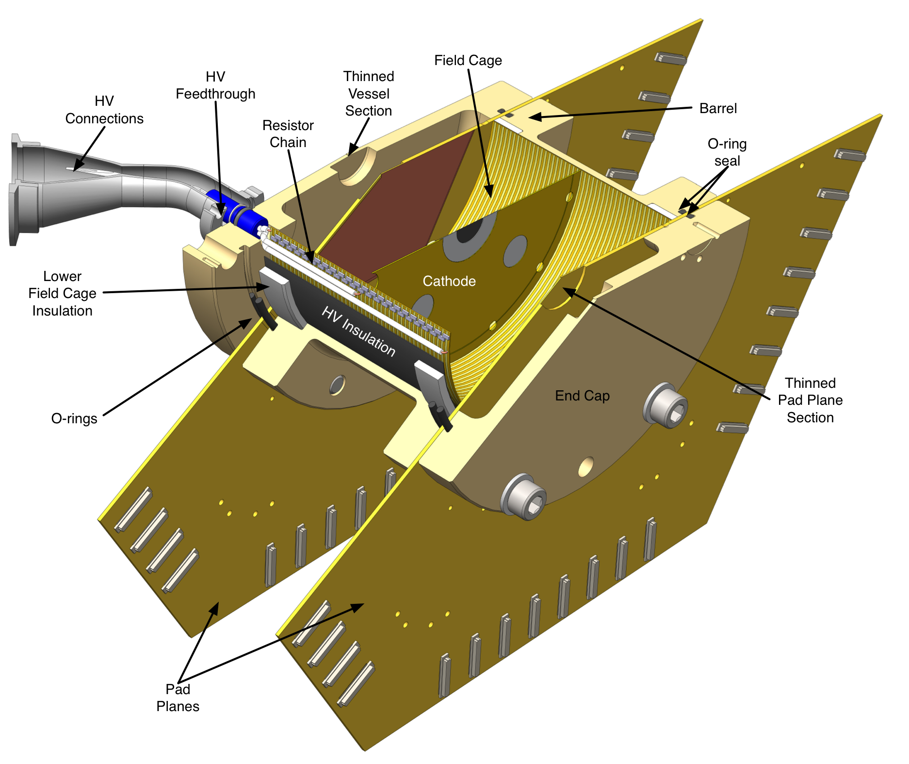
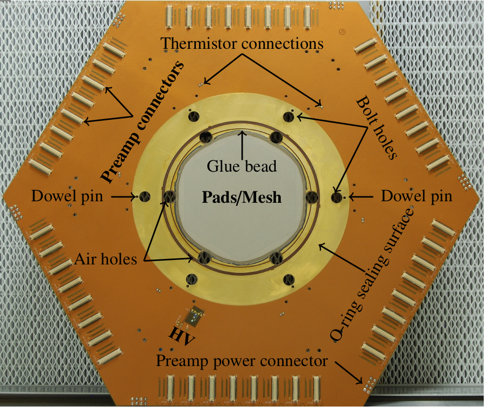
The fissionTPC has two volumes separated by a central cathode [3]. The total gas volume is liters with a 5.4 cm drift distance between each pad plane and the central cathode. The pad planes are 16-layer printed circuit boards with a total of 5952 hexagonal pads, each 2 mm in pitch. The MICROMEGAS consists of an electroformed nickel mesh, 3 m thick with 1000 lines per inch and a diameter of 140 mm. The mesh is held above a pad plane surface by dry film solder mask pillars 75 m tall and 500 m in diameter, and is secured to the perimeter with a conductive epoxy. The electric field in the drift and gain regions can be controlled independently. A cutaway of the fissionTPC is shown in Fig. 1 and a picture of the pad plane with a mesh attached can be seen in Fig. 2
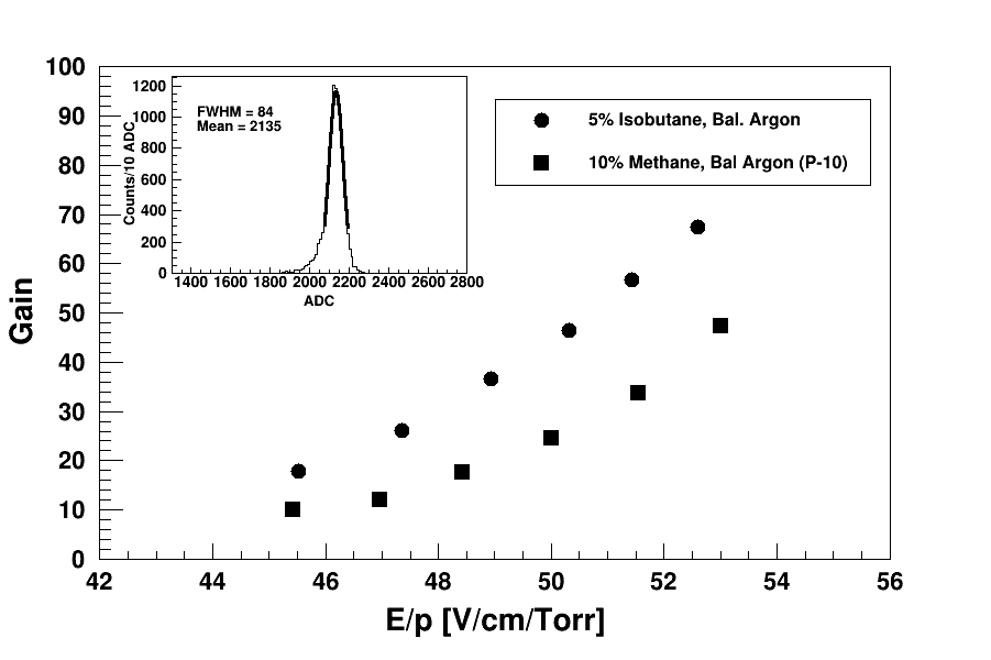
At the typical operating pressures of the fissionTPC (500–900 Torr), fission fragments will be stopped within several centimeters while depositing their full energy into the gas. The total kinetic energy released in neutron-induced fission is MeV [11, 12], with that energy being shared between two fragments. The short track lengths and high kinetic energies of fission fragments results in high-density primary electron clouds (about 106 electron–ion pairs) which allows the fissionTPC MICROMEGAS to operate at relatively low gains, ranging from 10–50. Fig. 3 shows a gain curve for two typical operating gases as a function of ratio of the applied electric field, , to the gas pressure, (the reduced electric field).
2.3 Gas System
The fissionTPC has a once-through gas system. The gas flow rates and pressure are maintained by an MKS 647C controller with an internal PID controller [13]. The 647C adjusts the flow rates based on a user-defined pressure setpoint, while the mixture is maintained by a flow ratio set by two inlet Mass Flow Controllers (MFC), one for Ar and one for the quench gas. The exchange rate is set by an independently controlled MFC on the exhaust side. The MFCs were MKS 1479A, and the pressure transducer used for the PID feedback signal was an MKS 627B. The Ar and quench gas inlet MFCs have a full scale of 1000 SCCM and 200 SCCM respectively, with an accuracy of 1% of full scale.
A calculation of the mixing rate shows that for an exchange rate of 300 SCCM the 2 L gas volume will achieve 99.99% of the desired composition in approximately 60 minutes. For each gas mixture in the experiment, the gas was exchanged for at least 1 hour at a rate of 300 SCCM before testing commenced. The purity of the Ar and CF4 gas was 99.999%, the CO2 was 99.99%, and the C4H10 was 99% with 5 ppm of water and the remaining contaminants consisted primarily of other alkanes.
2.4 Experimental Procedures
At the time of this experiment the fissionTPC was configured to measure neutron-induced fission cross sections and contained a target with deposits of 239Pu and 235U on the cathode. The activity of the 239Pu was approximately 0.425 MBq, with a comparatively negligible activity from the 235U of 10 Bq. The measurements, unless otherwise noted, took place at a pressure of 760 Torr. This pressure was chosen such that for any gas, ranging from pure Ar to pure quench gas, the 239Pu -particle tracks would be fully contained within the active area of the detector. The signal size of the peak corresponding to full energy deposition of 239Pu -particles was then used to determine the gain of the MICROMEGAS. The gain was adjusted to be the same for each gas mixture within 20% and was set near typical operating conditions for the fissionTPC for fission cross-section measurements. Additional data were collected at different pressures and higher gains to investigate the limits of MICROMEGAS stability.
Once the gain was set, the neutron beam shutter was opened and the MICROMEGAS was monitored for sparking, which is observed by a current trip of the high voltage system. The trip limit was set to 500 nA. The system was considered stable if no trips were observed after 60 minutes of exposure to the neutron beam. If a trip was observed in less than 60 minutes, the test was repeated for confirmation and a shutter-closed test of 60 minutes was conducted to confirm the instability was beam induced. The experiment is thus a measure of a the threshold above which sparking will begin to occur rather than a measure of a sparking rate or probability.
3 Results
The primary measurements for comparison between different gas types were taken at Torr, with the gain for each gas mixture adjusted to be similar (Table 1). Stability against sparking in the beam is primarily a function of the quantity of quench gas in the mixture. C4H10 and CO2 were stable with concentrations at or above 1%, CF4 required a concentration of 25% or greater, and CH4 was only tested at a concentration of 10% and found to be unstable. The following sections further describe the data collected at various gains and pressures.
| Quench Gas | Stability Conc. | (V/cm/Torr) | Gain |
|---|---|---|---|
| C4H10 | 1% | 33.3 | 21.8 |
| CO2 | 1% | 49.7 | 17.1 |
| CF4 | 25% | 61.2 | 18.8 |
| CH4 (P10) | – | 50.7 | 21.2 |
3.1 CH4
The initial gas explored for use in the fissionTPC was P10, a mixture of 90% Ar and 10% CH4. P10 is relatively cheap, provides fast drift speeds, and is commonly used in ionization chambers. When operating with P10 out of beam, the fissionTPC was found to be highly stable, running for hundreds of hours over a wide range of gains and pressures. P10 was found to be unstable to sparking in beam at Torr with a gain of 20. A stable point was found when operating at a lower pressure of 530 Torr. Table 2 shows the results of two tests at Torr, where the reduced electric field was varied to identify the transition to instability. At this lower pressure the gain could not be directly measured because the -particle tracks extended beyond the active area of the detector.
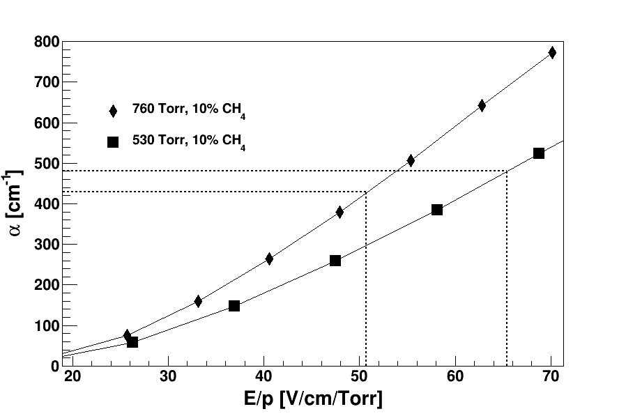
A Magboltz simulation [14] was completed to estimate the dependence of , the first Townsend coefficient, on the reduced electric field. This is shown for the two gas pressures tested in Fig. 4. Note that scales with [15, 16] and gain scales exponentially with . One can see that for Torr the stability point, 65.4, is at a higher value (and therefore gain) than the point at Torr and that was found to be unstable. This indicates that sparking is not only a function of gain but also ionization density. At lower pressures the stopping power is decreased, resulting in longer particle track lengths and a reduced primary ionization density. Therefore higher gain can be applied before the Raether limit is reached.
In addition to being stable out of beam, the system was stable in beam, with the drift field set to 0 V/cm and a nominal field in the gain stage. The interpretation of this result will be discussed further in Section 4.
| p (Torr) | Conc. | (V/cm/Torr) | Stable |
|---|---|---|---|
| 530 | 10% | 65.4 | Yes |
| 530 | 10% | 67.9 | No |
| 760 | 10% | 50.7 | No |
3.2 C4H10
A total of 6 configurations of C4H10/Ar gas mixtures were studied with different pressures, concentrations and gain (Table 3). The standard operating configuration for the fissionTPC when making cross section measurements is a mixture of 95% Ar and 5% C4H10 at Torr. This mixture and pressure are stable in beam, optimally utilize the detector active area for fission fragment and -particle tracks, and provide high gain at a relatively low MICROMEGAS bias voltage. A 5% C4H10 mixture was also tested at Torr, and the MICROMEGAS was found to be unstable for . A Magboltz simulation indicates that this onset of instability at Torr is at a lower gain than the configurations found to be stable at Torr (Fig. 5).
Additionally, a 1% C4H10 mixture was tested at Torr for comparison with the data point reported in Table 1. The decreasing pressure was again found to allow for a higher gain (Fig. 5). These finding generally agree with the CH4 results. Decreasing the charge density allows for a higher gain to be achieved before reaching the Raether limit. It should be noted that Ar/C4H10 is a Penning mixture and its gain will be substantially higher than what is calculated directly using the value [17] from the Magboltz simulation.
Stability against sparking was achieved with lower concentrations of C4H10 compared to CH4, indicating that photon quenching plays a role since C4H10 has a higher photoabsorption cross section [18].
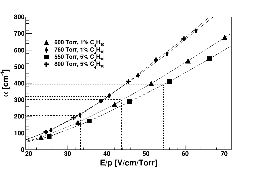
| p (Torr) | Conc. | (V/cm/Torr) | Stable |
|---|---|---|---|
| 600 | 1% | 43.8 | Yes |
| 760 | 1% | 33.3 | Yes |
| 550 | 5% | 48.5 | Yes |
| 550 | 5% | 54.5 | Yes |
| 800 | 5% | 39.8 | Yes |
| 800 | 5% | 40.6 | No |
3.3 CO2
CO2 is often used for its low diffusion and in systems requiring a non-flammable gas. The Ar–CO2 mixture was stable against sparking with lower concentrations and higher gain compared to the Ar–CH4 mixture (Table 4). CO2 has lower diffusion coefficients compared to CH4, and is effective at cooling electrons [19] which results in higher density charge clouds. It also has a higher photoabsorption cross section [18, 20] compared to CH4. In particular, its photoabsorption cross section is well matched to emission lines from excited states of Ar [21]. The stability of the Ar-CO2 mixture against sparking further indicates that the quenching of photons plays an important role in allowing in-beam operation.
| p (Torr) | Conc. | (V/cm/Torr) | Stable |
|---|---|---|---|
| 600 | 1% | 62.0 | Yes |
| 600 | 1% | 71.8 | Yes |
| 760 | 1% | 49.7 | Yes |
| 760 | 1% | 50.6 | Yes |
| 900 | 1% | 45.6 | Yes |
3.4 CF4
CF4 is useful as a drift gas in TPCs and wire chambers because of its fast electron drift speed, which improves performance for high rate applications. CF4 was found to be a much less effective quench gas when compared to CO2 and C4H10. The 25% CF4 mixture was on the edge of stability in the these tests. A slight increase in gain from the stable configuration at Torr shown in Table 1 resulted in sparking (Table 5), which continued for a 30% mixture at similar gain. A decrease in pressure to Torr allows for a higher gain to be achieved, as was seen for CH4 and C4H10.
In electron avalanches, CF4 produces a large number of photons [22], but it also has a low photoabsorption cross section to those photons [23]. While this is useful for scintillation, it limits the effectiveness of CF4 as a quench gas. The relative instability of the CF4 gas mixtures when compared to C4H10 and CO2 further supports the conclusion that photon quenching is an important factor in preventing sparking of the MICROMEGAS when in beam.
| p (Torr) | Conc. | (V/cm/Torr) | Stable |
|---|---|---|---|
| 600 | 30% | 75.2 | Yes |
| 760 | 25% | 61.2 | Yes |
| 760 | 25% | 62.6 | No |
| 760 | 30% | 66.2 | No |
4 Discussion
Sparking in a MICROMEGAS can result from spontaneous breakdown due to mesh defects, rate-induced effects, and highly ionizing particles [24]. Defects that cause spontaneous breakdowns essentially limit the maximum voltage any particular MICROMEGAS can sustain. In this study, each of the MICROMEGAS operating configurations was tested both in and out of beam to identify the cause of sparking. Rate-induced sparking is unlikely to be the cause since the beam-induced rate accounts for less than 2% of the total charge generated in the gain stage. This was measured via the current on the mesh, which primarily results from the spontaneous -decay of the 239Pu source. Fission fragments are the highest energy events observed in the fissionTPC and produce an exceptionally large amount of total ionization. They were eliminated as a cause by testing each of the gases (excepting CF4) with a 252Cf spontaneous fission source in the fissionTPC. It was observed that gases with good photon-quenching characteristics only required concentrations as low as 1% to be stable in beam. Overall, reducing gas pressure also allowed the MICROMEGAS to achieve higher gains while maintaining stability.
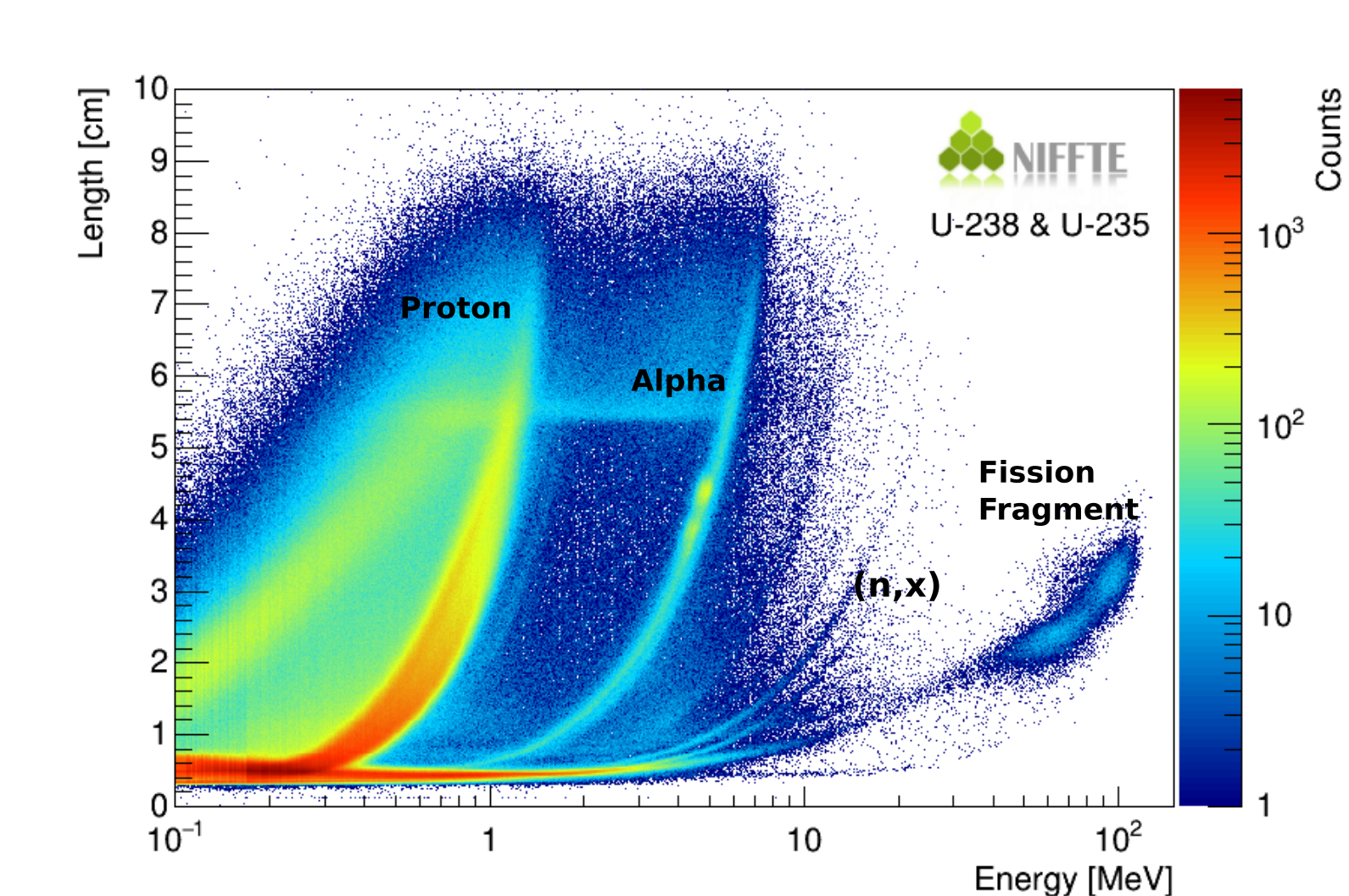
We conclude that the limiting factor for sparking in the MICROMEGAS is the density of the primary ionization clouds resulting from Ar recoils near the surface of the gain stage. A schematic representation of the fissionTPC and beam-induced events can be seen in Fig. 6. While recoils deposit a small amount of total ionization as compared to fission fragments, the ionization is deposited in a small volume of gas. Figure 7 shows a plot of track length versus energy for fissionTPC data collected with a mixture of 95% Ar and 5% C4H10. Between the fragment and -particle bands are several bands due to recoils of other nuclei present in the fisstionTPC gas and detector material. Between energies of 2–3 MeV, the bands become indistinguishable and drop below minimum track length resolution of the the fissionTPC which is limited by the 2 mm pixel size. These recoil events can produce as many primary electrons as an or proton track in a fraction of the length.
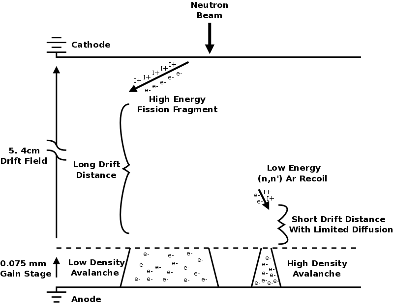
If the diffusion time is limited, a relatively low-energy gas recoil can have a greater charge density than a fission fragment of much higher energy. With a high enough space-charge density, a local electric field gradient can be produced in the gain stage that is sufficiently large to induce a discharge. This is the same effect that is referred to as exceeding the Raether limit. While the limit is commonly described in terms of a number of electrons, that is in reference to the gain when starting with only one electron. The actual mechanism described by Raether [8] corresponds to the space-charge of an avalanche being sufficient to develop a highly conductive plasma streamer directed at the anode. This is usually referred to as the rapid or streamer mechanism. Gas ionizing photons produced in the avalanche contribute to the portion of the streamer directed towards the cathode. This picture agrees with the observed improvements in stability when operating with the more effective photon-quenching gases C4H10 and CO2.
The effect of diffusion on charge density was calculated using SRIM and Magboltz [14, 25] for various energies and drift distances of two relevant cases: a typical fission fragment and Ar ions. A MeV 99Mo fission fragment in atm of argon gas has an ionization density at the start of the track (where ionization is highest for fission fragments and low energy heavy ions) more than 10 times that of a MeV Ar ion in the same gas. The fission fragments in the fissionTPC originate only from the central cathode and have a drift distance of 5.4 cm for charge deposited at the start of the track, while Ar recoils can occur at any point along the drift axis. Comparing the charge density within 1 of the transverse diffusion radius, assuming a uniform distribution, one finds that the charge produced by a MeV Ar ion drifting 1 mm has an ionization density at the beginning of the track approximately 5 times that of a fission fragment that has drifted 5.4 cm. Increasing the Ar ion energy to MeV increases the ionization density by a factor 20. This is supported by the observed improvement in stability when operating at reduced pressures, which generally decreases the ionization density by extending the track length.
In Section 3.1 it was reported that no discharges were observed when setting the drift field to while maintaining an applied field across the gain stage. If discharges are a result of Ar recoils, sparking should in principle still occur in this configuration. The stability criteria was defined for this experiment as 60 minutes of no observed discharges (see Section 2.4). The drift field data point meet this criteria. For all the discharges that were recorded in this experiment the average time between being exposed to beam and observing a spark was 10 minutes, with no discharge taking more that 20 minutes to occur. While the full observation period is 6 times longer that the average discharge rate, the 75um gain stage only represents 0.14% of the total volume and correspondingly of the Ar recoil events. It is therefore plausible that no discharges occurred during the observation period.
Furthermore when the drift field is absent, only the fraction of charge deposited directly in the gap contributes to the avalanche, since all charge outside the gap would not drift. For example a 1 MeV Ar recoil has a particle range of over 2.5mm in 760 torr of Argon gas, and deposits less than 10% of its total charge in the first 100 um of track length. While our argument is that charge density is the leading factor in inducing a spark, it is likely that discharges are not only a function of charge density but also of total charge in the event.
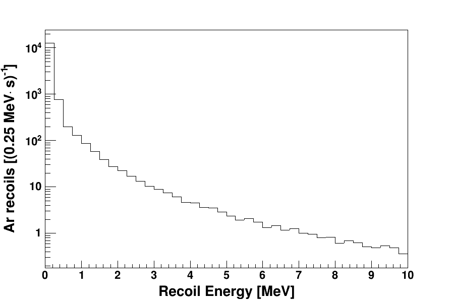
This experiment was a measure of a threshold effect whereby the MICROMEGAS either discharged or was stable for an extended time, as was described in section 2.4. The discharging rate varies strongly and non-linearly with gain. Without a much more detailed simulation of the discharge process or dedicated data observations it is unclear which specific recoil energies over which drift distances lead to discharges for a given gas mixture and gain. We did however run a simulation to provide a semi-quantitative check on whether Ar recoils were a plausible cause for discharging at the rates observed. Figure 8 shows the expected rate and energy of Ar recoils in one volume of the fissionTPC with a gas mixture of 95% Ar and 5% C4H10 at a pressure of torr. The results are from an MCNP simulation of the fissionTPC in the 90L beam line at WNR-LANSCE. The total rate of Ar recoils over all energies is approximately per second. As a specific example previously in this section it was discussed that a MeV Ar recoil drifting mm results in an ionization density 5 times that of a fission fragment. The rate of Ar recoils in the energy range of – MeV within mm of the surface of the MICROMEGAS is approximately per second. The simulation shows that there are a sufficient number of high-energy Ar recoils expected in the fissionTPC to produce the observed discharges.
If Ar recoils are the primary cause of sparking, gas mixtures made of lighter noble gases such as helium or neon should prove to be more stable. An initial observation indicates that the fissionTPC is able to achieve gains approximately twice as high in a Ne–C4H10 mixture, however a systematic study has not been conducted at this time. While a similar conclusion was reached in Ref. [26], a direct comparison with these measurements is difficult since the beam, target, pressures and gains used were in a considerably different regime than the fissionTPC operating conditions.
5 Conclusions
We have studied the stability of a MICROMEGAS against sparking when operated in a high-energy high-flux neutron beam. Several Ar-based gas mixtures relevant to TPC design were investigated. Nuclear recoils from neutron scattering near the mesh, which result in high-density ionization tracks, were identified as the cause of sparking instability. When the recoil interactions occurs near the mesh, the diffusion distance is reduced and consequently the charge density of the ion cloud is high, leading to the Raether limit being exceeded. Quench gases C4H10 and CO2 with high photoabsorption cross sections required lower concentrations to achieve stability against breakdown as compared to CH4 and CF4. Overall, reducing the pressure of the operating gas allowed for higher operating gains. Use of gas mixtures based on nuclides lighter than Ar should also provide stability at high gains for MICROMEGAS in neutron beams.
6 Acknowledgments
The neutron beam for this work was provided by LANSCE, which is funded by the U.S. Department of Energy and operated by Los Alamos National Security, LLC, under contract DE-AC52-06NA25396. This work performed under the auspices of the U.S Department of Energy by Lawrence Livermore National Laboratory under contract DE-AC52-07NA27344. This material is based upon work supported by the U.S. Department of Energy, National Nuclear Security Administration, Stewardship Science Academic Alliances Program, under Award Number DE-NA0002921. LLNL-JRNL-722401
References
- [1] Y. Giomataris, P. Rebourgeard, J. Robert, G. Charpak, Micromegas: a high-granularity position-sensitive gaseous detector for high particle-flux environments, Nuclear Instruments and Methods in Physics Research Section A: Accelerators, Spectrometers, Detectors and Associated Equipment 376 (1) (1996) 29 – 35. doi:http://doi.org/10.1016/0168-9002(96)00175-1.
- [2] J. Marx, D. Nygren, The time projection chamber, Physics Today 31 (1978) 46.
- [3] M. Heffner, D. Asner, R. Baker, J. Baker, S. Barrett, C. Brune, J. Bundgaard, E. Burgett, D. Carter, M. Cunningham, J. Deaven, D. Duke, U. Greife, S. Grimes, U. Hager, N. Hertel, T. Hill, D. Isenhower, K. Jewell, J. King, J. Klay, V. Kleinrath, N. Kornilov, R. Kudo, A. Laptev, M. Leonard, W. Loveland, T. Massey, C. McGrath, R. Meharchand, L. Montoya, N. Pickle, H. Qu, V. Riot, J. Ruz, S. Sangiorgio, B. Seilhan, S. Sharma, L. Snyder, S. Stave, G. Tatishvili, R. Thornton, F. Tovesson, D. Towell, R. Towell, S. Watson, B. Wendt, L. Wood, L. Yao, A time projection chamber for high accuracy and precision fission cross-section measurements, Nuclear Instruments and Methods in Physics Research Section A: Accelerators, Spectrometers, Detectors and Associated Equipment 759 (2014) 50 – 64. doi:http://doi.org/10.1016/j.nima.2014.05.057.
- [4] F. Belloni, S. Andriamonje, E. Berthoumieux, M. Calviani, E. Chiaveri, N. Colonna, Y. Giomataris, C. Guerrero, F. Gunsing, F. Iguaz, M. Kebbiri, J. Pancin, T. Papaevangelou, A. Tsinganis, V. Vlachoudis, S. Altstadt, J. Andrzejewski, L. Audouin, M. Barbagallo, V. Bécares, F. Bečvář, J. Billowes, V. Boccone, D. Bosnar, M. Brugger, F. Calviño, D. Cano-Ott, C. Carrapiço, F. Cerutti, E. Chiaveri, M. Chin, G. Cortés, M. Corté-Giraldo, M. Diakaki, C. Domingo-Pardo, I. Duran, N. Dzysiuk, C. Eleftheriadis, A. Ferrari, K. Fraval, S. Ganesan, A. García, G. Giubrone, M. Gómez-Hornillos, I. Gonçalves, E. González-Romero, E. Griesmayer, P. Gurusamy, D. Jenkins, E. Jericha, Y. Kadi, F. Käppeler, D. Karadimos, P. Koehler, M. Kokkoris, M. Krtička, J. Kroll, C. Langer, C. Lederer, H. Leeb, L. Leong, R. Losito, A. Manousos, J. Marganiec, T. Marítnez, C. Massimi, P. Mastinu, M. Mastromarco, M. Meaze, E. Mendoza, A. Mengoni, P. Milazzo, F. Mingrone, M. Mirea, W. Mondalaers, C. Paradela, A. Pavlik, J. Perkowski, A. Plompen, J. Praena, J. Quesada, T. Rauscher, R. Reifarth, A. Riego, F. Roman, C. Rubbia, R. Sarmento, P. Schillebeeckx, S. Schmidt, G. Tagliente, J. Tain, D. Tarrío, L. Tassan-Got, S. Valenta, G. Vannini, V. Variale, P. Vaz, A. Ventura, R. Versaci, M. Vermeulen, R. Vlastou, A. Wallner, T. Ware, M. Weigand, C. Weiss, T. Wright, P. Žugec, A micromegas detector for neutron beam imaging at the nTOF facility at CERN, Nuclear Data Sheets 119 (2014) 365 – 367. doi:http://doi.org/10.1016/j.nds.2014.08.100.
- [5] J. Pancin, S. Aune, E. Berthoumieux, S. Boyer, E. Delagnes, V. Macary, B. Poumarede, H. Safa, Neutron detection in high background using a micromegas detector, Nuclear Instruments and Methods in Physics Research Section A: Accelerators, Spectrometers, Detectors and Associated Equipment 572 (2) (2007) 859 – 865. doi:http://doi.org/10.1016/j.nima.2006.12.010.
- [6] S. Andriamonje, S. Aune, G. Bignan, C. Blandin, E. Ferrer, I. Giomataris, C. Jammes, J. Pancin, New neutron detectors based on micromegas technology, Nuclear Instruments and Methods in Physics Research Section A: Accelerators, Spectrometers, Detectors and Associated Equipment 525 (1–2) (2004) 74 – 78. doi:http://doi.org/10.1016/j.nima.2004.03.126.
- [7] C. Golabek, J. Billard, A. Allaoua, G. Bosson, O. Bourrion, C. Grignon, O. Guillaudin, L. Lebreton, F. Mayet, M. Petit, J.-P. Richer, D. Santos, A detector for the characterization of low energy neutron fields, Nuclear Instruments and Methods in Physics Research Section A: Accelerators, Spectrometers, Detectors and Associated Equipment 678 (2012) 33 – 38. doi:http://doi.org/10.1016/j.nima.2012.03.003.
- [8] H. Raether, Electron Avalanches and Breakdown in Gas, Butterworths, 1964.
- [9] P. W. Lisowski, K. F. Schoenberg, The los alamos neutron science center, Nuclear Instruments and Methods in Physics Research Section A: Accelerators, Spectrometers, Detectors and Associated Equipment 562 (2) (2006) 910 – 914. doi:http://doi.org/10.1016/j.nima.2006.02.178.
- [10] F. Tovesson, Uncertainty quantification in fission cross section measurements at lansce, Nuclear Data Sheets 123 (2015) 124 – 129, special Issue on International Workshop on Nuclear Data Covariances April 28 - May 1, 2014, Santa Fe, New Mexico, USA http://t2.lanl.gov/cw2014. doi:http://dx.doi.org/10.1016/j.nds.2014.12.022.
- [11] K. Meierbachtol, F. Tovesson, D. L. Duke, V. Geppert-Kleinrath, B. Manning, R. Meharchand, S. Mosby, D. Shields, Total kinetic energy release in post-neutron emission from 0.5 to 50 mev incident neutron energy, Phys. Rev. C 94 (2016) 034611. doi:10.1103/PhysRevC.94.034611.
- [12] R. Yanez, L. Yao, J. King, W. Loveland, F. Tovesson, N. Fotiades, Excitation energy dependence of the total kinetic energy release in ,, Phys. Rev. C 89 (2014) 051604. doi:10.1103/PhysRevC.89.051604.
-
[13]
MKS 647C Multi Channel Flow
Ratio/Pressure Controller.
URL https://www.mksinst.com/docs/ur/647.pdf - [14] S. Biagi, A multiterm Boltzmann analysis of drift velocity, diffusion, gain and magnetic-field effects in argon-methane-water-vapour mixtures, Nuclear Instruments and Methods in Physics Research Section A: Accelerators, Spectrometers, Detectors and Associated Equipment 283 (3) (1989) 716 – 722. doi:http://doi.org/10.1016/0168-9002(89)91446-0.
- [15] T. Aoyama, Generalized gas gain formula for proportional counters, Nuclear Instruments and Methods in Physics Research Section A: Accelerators, Spectrometers, Detectors and Associated Equipment 234 (1) (1985) 125 – 131. doi:http://doi.org/10.1016/0168-9002(85)90817-4.
- [16] A. Sharma, F. Sauli, A measurement of the first Townsend coefficient in argon based mixtures at high fields, Nuclear Instruments and Methods in Physics Research Section A: Accelerators, Spectrometers, Detectors and Associated Equipment 323 (1–2) (1992) 280 – 283. doi:http://doi.org/10.1016/0168-9002(92)90303-L.
- [17] Ö. Şahin, İ. Tapan, E. N. Özmutlu, R. Veenhof, Penning transfer in argon-based gas mixtures, Journal of Instrumentation 5 (05) (2010) P05002.
- [18] K. Kameta, N. Kouchi, M. Ukai, Y. Hatano, Photoabsorption, photoionization, and neutral-dissociation cross sections of simple hydrocarbons in the vacuum ultraviolet range, Journal of Electron Spectroscopy and Related Phenomena 123 (2–3) (2002) 225 – 238. doi:http://doi.org/10.1016/S0368-2048(02)00022-1.
- [19] X. Bittl, V. Eckardt, H. Fessler, W. Gong, M. Konrad, A. Mock, A. Odian, P. Seyboth, J. Draper, M. Hildebrandt, K. Ness, B. Schmidt, Diffusion and drift studies of Ar-DME/CO2/CH4 gas mixtures for a radial TPC in the E B field, Nuclear Instruments and Methods in Physics Research Section A: Accelerators, Spectrometers, Detectors and Associated Equipment 398 (2–3) (1997) 249 – 264. doi:http://doi.org/10.1016/S0168-9002(97)00703-1.
- [20] D. Shaw, D. Holland, M. Hayes, M. MacDonald, A. Hopkirk, S. McSweeney, A study of the absolute photoabsorption, photoionisation and photodissociation cross sections and the photoionisation quantum efficiency of carbon dioxide from the ionisation threshold to 345 Å, Chemical Physics 198 (3) (1995) 381 – 396. doi:http://doi.org/10.1016/0301-0104(95)00159-L.
- [21] Ö. Şahin, T. Kowalski, R. Veenhof, High-precision gas gain and energy transfer measurements in ar–co2 mixtures, Nuclear Instruments and Methods in Physics Research Section A: Accelerators, Spectrometers, Detectors and Associated Equipment 768 (2014) 104 – 111. doi:http://doi.org/10.1016/j.nima.2014.09.061.
- [22] A. Kaboth, J. Monroe, S. Ahlen, D. Dujmic, S. Henderson, G. Kohse, R. Lanza, M. Lewandowska, A. Roccaro, G. Sciolla, N. Skvorodnev, H. Tomita, R. Vanderspek, H. Wellenstein, R. Yamamoto, P. Fisher, A measurement of photon production in electron avalanches in CF4, Nuclear Instruments and Methods in Physics Research Section A: Accelerators, Spectrometers, Detectors and Associated Equipment 592 (1–2) (2008) 63 – 72. doi:http://doi.org/10.1016/j.nima.2008.03.120.
- [23] A. Pansky, A. Breskin, A. Buzulutskov, R. Chechik, V. Elkind, J. Va’vra, The scintillation of CF4 and its relevance to detection science, Nuclear Instruments and Methods in Physics Research Section A: Accelerators, Spectrometers, Detectors and Associated Equipment 354 (2–3) (1995) 262 – 269. doi:http://doi.org/10.1016/0168-9002(94)01064-1.
- [24] A. Bay, J.-P. Perroud, F. Ronga, J. Derré, Y. Giomataris, A. Delbart, Y. Papadopoulos, Study of sparking in micromegas chambers, Nuclear Instruments and Methods in Physics Research Section A: Accelerators, Spectrometers, Detectors and Associated Equipment 488 (1–2) (2002) 162 – 174. doi:http://doi.org/10.1016/S0168-9002(02)00510-7.
- [25] J. F. Ziegler, M. Ziegler, J. Biersack, SRIM – the stopping and range of ions in matter (2010), Nuclear Instruments and Methods in Physics Research Section B: Beam Interactions with Materials and Atoms 268 (11–12) (2010) 1818 – 1823. doi:http://doi.org/10.1016/j.nimb.2010.02.091.
- [26] A. Delbart, J. Derré, Y. Giomataris, F. Jeanneau, I. Papadopoulos, Performance of MICROMEGAS with preamplification at high intensity hadron beams, Nuclear Instruments and Methods in Physics Research Section A: Accelerators, Spectrometers, Detectors and Associated Equipment 478 (1–2) (2002) 205 – 209. doi:http://doi.org/10.1016/S0168-9002(01)01758-2.