WiPLoc: Perpetual Indoor Localization with RF Wireless Power Transfer
Abstract
Indoor localization is a cornerstone of mobile services. Until now most of the research effort has focused on achieving sub-meter localization accuracy because many mobile applications depend on precise localization measurements. In some scenarios, however, it is required to trade location accuracy for system maintainability. For example, in large-scale deployments of indoor networks, such as item-monitoring in smart buildings, attaining room-level localization accuracy may be sufficient, but replacing the batteries of the devices used for localization could lead to high operational costs. As indoor localization systems grow in popularity it will be important to provide them with full energy autonomy. To tackle this problem we propose WiPLoc: an indoor localization system aimed at operating perpetually without batteries. Our contributions are twofold. First, we propose a novel localization method that exploits capture effect and orthogonal codes to operate at energy levels that are low enough to operate within the energy budget provided by long-range wireless power transmission. Second, we implement WiPLoc using off-the-shelf components and test it extensively in a laboratory environment. Our test results show that with WiPLoc one wireless charger per (16 m) room can enable perpetual lifetime operation of mobile objects requiring localization with an average accuracy of almost 90%.
I Introduction
Indoor localization is a topic that has been investigated for more than a decade [1, 2]. Yet, no single system exists that is widely adopted as the de facto localization standard. From a research perspective the goal is to obtain a solution that is general, simple and accurate [2]. But as the number of devices in the Internet of Things grow, a new set of challenges are appearing: (i) maintainability, (ii) low operational costs, and more importantly, (iii) energy autonomy.
I-A Motivation: Indoor Localization with Wireless Power
In large-scale indoor localization scenarios [3] the cost of replacing the batteries of thousands of anchor nodes (devices sending location information) and mobile nodes (devices to be localized) is high.
Example: Amsterdam Schiphol Airport has roughy 10 000 Bluetooth Low Energy (BLE) beacons deployed to provide navigation services. In order to maintain the operation of all BLE beacons, battery status monitoring mechanism of the localization beacons must be implemented. These include measuring beacon signal strength by crossing the entire airport area [4] or beacon signal strength crowdsourcing.
The research community has recognized this autonomous energy challenge and therefore the area of Wireless Power Transfer (WPT) starts to gain momentum [5, 6]. In WPT systems a charger radiates energy in the form of electromagnetic or mechanical waves to receivers that harvest this energy. It would be thus valuable to combine the emerging area of WPT with the established area of indoor localization to propose a novel positioning system.
Challenges of RFID localization: The idea of battery-less localization is not new. Radio Frequency Identification (RFID) has been extensively researched for this purpose. Unfortunately, RFID-based localization has some inherent limitations. First, most RFID localization approaches, e.g. [7], require pre-deployed anchor tags, where portable RFID readers estimate their position by detecting nearby backscatter signals from tags. Although the RFID tags are batteryless, the mobile reader requires a lot of energy during tag scanning [8, Table I], and due to the fast attenuation of backscatter signals, the density of RFID tags must be high. Second, RFID technology is also used in tracking systems [9], where mobile nodes carry a passive tag and static readers are used to track their location. In principle, this system is similar to ours, with WPT chargers playing the role of RFID readers. But WiPLoc has the added advantage of having both the monitoring system and the tag itself being aware of the location. With RFID tracking, only the system knows the location of the tags, but the tags themselves are not aware of their own location.
I-B Wireless Powered Indoor Localization: Research Challenge
Localization and WPT are well researched topics on their own, but using WPT for localization entails a substantial challenge. The problem is that WPT provides amounts of power that are too small for the operation of most radio-based localization systems. For example, experimenting with TX91501 power transmitter [10], due to the exponential decay of signal strength, the harvested power is 0.79 mW at 3 m. However, highly energy-efficient radios, such as BLE nodes, consume around 25 mW in receiving mode. This small amount of power is insufficient for not only receiving packets from many anchor nodes but also to synchronize the operation of the localization system.
Research Question: Based on the observation above we define the research problem as: given the limited harvested energy from WPT, how should a system manage the indoor localization process to achieve continuous and perpetual localization?
I-C Our Contributions
Considering the research question described above we propose a unified set of solutions for wirelessly powered indoor localization. Namely:
Contribution 1: To minimize the radio transmission and receiving time of localization and meet the limited harvested energy supply, we propose a novel localization method where all anchors transmit localization messages simultaneously and the induced collisions are resolved via orthogonal codes. The key advantage of this approach is that the radios of all nodes, including anchor nodes and nodes requiring localization, are active only for the duration of a single message transmission.
Contribution 2: We implement and evaluate an operational system using off-the-shelf BLE motes [11] and WPT chargers and harvesters [10]. Based on systematic experiments in an office environment, we demonstrate that WiPLoc can achieve perpetual indoor localization with room-level (16 m) and cell-level ( 4 m) accuracies of approximately 90% and 70%, respectively. To the best of our knowledge, WiPLoc is the first system that successfully achieves room-level localization using the energy of RF based WPT.
The rest of the paper is organized as follows. The related work is discussed in Section II. Our basic battery-less localization method achieving room-level accuracy, denoted as WiPLoc, is presented in Section III, while its experimental evaluation is presented in Section IV. Approaches to further save power and increase localization accuracy, denoted as WiPLoc++, are presented in Section V, with its detailed evaluation presented in Section VI. Finally, we present our conclusions in Section VII.
II Related Work
II-A Localization with Wireless Power Transfer
The field of (indoor) localization has been researched for years [1, 2]. Interestingly engough to the best of our knowledge, we are not aware of any localization technique that uses WPT except for TOC [12]. TOC obtains location information based on the time of charge provided by mobile chargers to the static nodes being localized. Unfortunately (i) TOC requires frequent position changes of mobile charger to obtain reasonable location accuracy and (ii) has been tested in outdoors only. TOC belongs to a static receiver/mobile charger WPT network type. Following the categorization of [8, Sec. III-A], none of three remaining categories have been applied for localization (either indoor or outdoor). Specifically, localization infrastructure where static charger (not obstructing the area of localization) and mobile receiver being localized, which is the most desired.
II-B Localization with RFID
Localization based on RFID technology is developing rapidly in recent years. These approaches can be classified into three categories [13, Sec.III]. In the first category, RFID reader-based localization system, e.g. [14, 7], allocates RFID reader in the object requiring localization to detect the pre-deployed anchor tags nearby. Although the deployment and maintenance cost of RFID tags are low, the localization lifetime depends on the limited battery of mobile readers. In the second category, RFID tag-based localization system, e.g. [9, 15], tracks the location of object attached with RFID tag by pre-deployed readers. The advantage of this approach is that the lifetime of tags is unlimited. However, the localization range is limited by the density of readers. Also, the tags cannot be localized once they are outside the range of readers. In the last category, RFID device-free localization system, e.g. [16], detects the position of target wearing no additional localization devices. The idea is to find the target location by detecting and comparing the change of RFID signal in the environment. Tag-based and device-free localization are both passive localization/tracking, which do not fall into the research area of this paper.
III WiPLoc: Wirelessly-Powered Localization
We propose a new indoor localization method for a freely moving device that trades-off accuracy for power consumption. The goal is to reduce the energy consumption of the localization system to a level allowing to power the localization infrastructure wirelessly over large distances.
Selection of WPT technology. While many WPT techniques exist [5, Table 1] we chose the one based on Radio Frequency (RF) for two reasons. First, RF signals can serve the dual purpose of providing localization and energy. This simplifies the design, operation and cost of anchors and tags compared to systems using different signals for localization and energy transfer, such as sound or magnetic resonance. Secondly, it is the most promising WPT technology as it allows for long-range power transfer even with small receiver antennas, which is challenging with other WPT technologies such as induction-based WPT.
How WiPLoc enables WPT-based localization. The main idea behind WiPLoc’s low power consumption is to exploit synchronous packet transmissions to reduce the radio activity time and, in-turn, collision resolution through improved packet capture. In the subsequent sections we will introduce two main WiPLoc processes: (i) localization (Section III-A) and (ii) wireless energy supply (Section III-B), in detail.
III-A WiPLoc: Localization Protocol
To get a clear understanding of how WiPLoc localization works we introduce all localization building blocks in detail.
III-A1 Deployment Area
The system is designed for indoor use. WiPLoc’s aim is to find a location of the moving object within strictly defined localization areas, i.e. rooms of an office environment.
III-A2 Components
The WiPLoc system consist of two building blocks: (i) Anchor Nodes and (ii) Mobile Nodes that want to be localized.
-
•
Anchor Node: This node is deployed as static in a room and placed at specific locations that maximize signal reception by the Mobile Node in that room. The Anchor Node is pre-programmed with a unique ID that correlates with that specific room. The Anchor Node is constantly powered via a cable and is always in a receiving mode. For deployment simplicity each room has only one Anchor Node.
-
•
Mobile Node: This node can move between rooms and is powered by some form of wireless energy. The Mobile Node is constantly in sleeping mode and only wakes up after a pre-defined time after which it goes back to sleep. It has a pre-defined table with all anchor IDs to correlate the Anchors Nodes with a location (room).
III-A3 Localisation Algorithm
The network is consisting of Anchor Nodes and Mobile Nodes, where the Mobile Nodes are localized by receiving the ID of the strongest anchor. WiPLoc localization belongs therefore to the proximity-based methods of indoor localization systems [17, Sec. II-C].
Localization methods that use packet radio are usually asynchronous to avoid collisions among packets sent by other anchors. In WiPLoc however, all anchors send their packets at the same time, enforcing packet collisions. The mobile node leverages the capture effect [18, Sec. II-A] to decode the strongest signal and assigns its location to that anchor. The key advantage of this method is its energy efficiency: Anchors and Mobile Nodes in the WiPLoc network only need to be active for a single packet transmission and reception time slot. A separate discussion is needed on packet synchronization, collision resolution and error correction.
Packet Synchronisation
The packets from the anchors need to arrive at the Mobile Node at the same time. For example, in our protocol each packet consists of a preamble of one byte, a payload and a CRC of the whole packet. To leverage the capture effect the packets should arrive within each other’s preamble at the Mobile Node. To achieve this synchronization the Mobile Node broadcasts a location-request packet. This is a synchronization packet that instructs all receiving anchors to immediately respond with their ID encoded in a payload. Leveraging the capture effect alone however has limitations [19, Sec. IV]. For the capture effect to work the strongest signal needs a certain minimum SINR. If this requirement is not satisfied, packets will collide and the anchor ID will not be retrieved.
Orthogonal Spreading Codes
To overcome this limitation the Anchor Node ID is encoded with an orthogonal code to increase inter-packet distinction. Each bit of the Anchor Node ID is multiplied by an orthogonal code unique for each anchor. The encoded Anchor Node ID is then send in the payload of a packet. The decoding process at each mobile node is an XOR operation between the payload of received packet with a list of orthogonal codes. In this paper a Hadamard matrix of size is used to generate the codes111Any other method can be used as long as the codes all have zero cross-correlation with each other., i.e.,
| (1) |
where , and is the Kronecker product.
FEC layer
Although orthogonal codes have a build-in tolerance for bit errors they are unable to decode them all. For this reason the Anchor Node ID is first encoded with a Forward Error Correcting (FEC) code, before it is multiplied by the orthogonal codes. The FEC layer is constructed of maximum minimum Hamming distance codes [20] i.e. codes having equal Hamming distance to each other. The decoding of the FEC layer uses minimum distance decoding.
III-A4 Illustration—Eliminating Localization Dead Zone
To verify that the orthogonal codes are working correctly the following experiment was performed.
Experiment Hardware
For convenience we select the nRF51822 SoC with a ARM Cortex M0 from Nordic Semiconductor with BLE support [11] as hardware platform to test the localization protocol. For WiPLoc however, we do not use the BLE protocol stack but use the radio peripheral of the nRF51822 and introduce our own packet and communication protocol instead. We refer to [21] for the source code of the implementation.
-
•
Anchor Node: The Smart Beacon Kit form Nordic Semiconductor [11] is used. This module has a coin size form factor with a PCB integrated antenna.
-
•
Mobile Node: The Nordic Semicoductor PCA10005 [11] is used. It has an SMA connector with a connected quarter-wave helical monopole antenna of 1.6 dBi gain222In the rest of the papers we will refer to both devices as nRF51822..
Experiment Setup
Two anchors are placed two meters apart and the mobile node is placed at 20 points in a straight line between the anchors with each measurement point separated 10 cm from each other. The transmission power of the Anchor Nodes are set to 0 dBm. The mobile node stays at each point for around 30 s and sends localization request every second. First the localization experiment was performed without orthogonal codes. After that the same experiment was performed with orthogonal codes.
Experiment Results
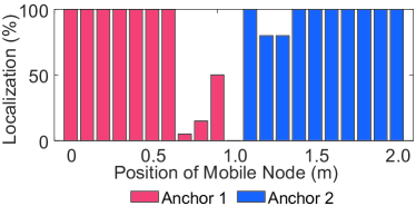
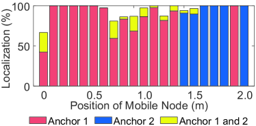
In Fig. 1(a) we observe that in-between anchors, we obtain a dead zone, i.e. area of no reception because in this region the SINR is insufficient to receive a correct packet and the packets collides which causes the packets to deform. Fig. 1(b) demonstrates that the dead zone is eliminated with orthogonal codes. Furthermore, we observe that multiple anchor IDs can be decoded from one packet. We call this phenomenon multi-packet reception. The reason for the larger coverage of Anchor 1 in Fig. 1(b) is due to use of antenna with a different coverage pattern in that experiment.
III-B WiPLoc: Wireless Energy Supply
Having low power features of WiPLoc implemented, we are ready to extend WiPLoc with wireless power localization features. As in Section III-A we describe all localization blocks with WPT enabled.
III-B1 Components
The WiPLoc components described in Section III-A are in this section extended with WPT functionality.
-
•
Anchor Node: As the anchor nodes are located at static and central in a room we combine them with a power transmitter. This transmitter should provide full coverage for one room.
-
•
Mobile node: This node is combined with a power harvester that harvests RF power form the RF power transmitter. Note that the WPT channel is different than the communication channel.
III-B2 Software Implementation
The localization algorithm is the same as in Section III-A however to enable it with WPT the following steps have been taken. To keep the power consumption at a minimum all the peripherals of the Mobile Node are turned off except for one hardware timer which is set to generate an interrupt333We again refer to [21] for the source code of the implementation. at each period . The CPU of the nRF51822 is most of the time in Wait For Interrupt (WFI) state, which we denote as the sleep state. When the interrupt is executed the nRF51822 is woken up and begins a localization round. The localization round starts broadcasting a location-request. Next, the radio directly switches to receiving mode. If a valid location packet is received (meaning the CRC is correct) decoding the anchor ID is trivial. On the other hand, if the received packet is corrupted the orthogonal codes inside ensure that the anchor ID can still be decoded from the packets. After this the Mobile Node goes back to sleep. The complete program flow is depicted in Algorithm 1.
Anchor Node:
Mobile Node:
There are two types of packets sent by the WiPLoc protocol. Both types have a fixed payload length of 30 bytes. Next section will elaborate on how the payload of the packets is constructed for each type.
Location Request Packet
The location-request packet contains in the first two bytes of the payload the group ID of anchors. The group ID of all anchors is the arbitrary integer . The anchors are then programmed to accept all packets that contain this integer in the first two bytes. The packet send back by the Anchor to the Mobile Node is a location-reply packet.
Location Reply Packet
The location-reply packet contains in the payload the anchor ID encoded by the FEC layer which is then encoded by the orthogonal codes and this is stored in the payload of the packet.
Location Reply Encoding Process
All the Anchor Nodes have an array , with FEC codes having an equal Hamming distance to each other. The anchor ID is then FEC encoded by replacing the anchor ID with a -th FEC code from the array. The orthogonal codes are generated using the method described in Section III-A3. For the generated matrix each symbol is replaced with a and each row of the matrix represents a binary spreading code. Finally, every bit of the FEC code is represented by the -th orthogonal code from the array. If the bit is zero, the bitwise NOT of the orthogonal code is used444The size of the orthogonal codes is 16 bits and this results in a total message length of 30 bytes that fits in the payload of the radio packet..
Location Reply Decoding Process
As stated in Section III-A also the Mobile Node has an array of all orthogonal and FEC codes used by the anchors. For every entry in the orthogonal code array the Mobile Node tries to decode the packet. When a candidate anchor ID is found, the decoded code is compared to the correlating FEC code of the candidate ID. When the Hamming distance of the candidate FEC code compared to a code from the FEC array follows we assume that the candidate ID is the correct one. The decoding stops when the last orthogonal code in the array is used to decode a packet. The source code accompanying this paper is available at [21].
III-B3 Hardware Implementation
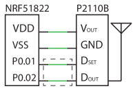
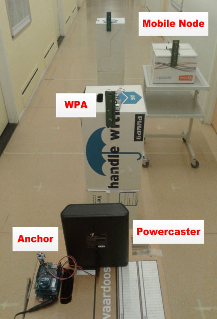
The WiPLoc localization components are connected as follows, see Fig. 2:
-
•
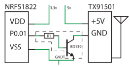
Anchor Node: This node is combined with the Powercast TX91501 Powercaster transmitter [10]. It has an Effective Isotropic Radiated Power (EIRP) of 3 W and operates at a RF center frequency of 915 MHz. There is no signal connecting the powercaster to the nRF51882. The Powercaster is always active and is always sending RF energy into the environment. In the rest of the paper we will refer to this component as powercaster.
-
•
Mobile Node: The Powercast P2110B power harverster [10] is used as power supply for the nRF51822. It is a development PCB with a SMA connector for connecting an antenna for harvesting power. Two antennas can be selected: (i) a vertical polarized omni-directional dipole antenna with 1.0 dBi gain and (ii) a vertical polarized patch antenna with a 6.1 dBi gain. We will refer to this component as the harvester.
IV WiPLoc: Experiment results
From [22] we know that the lower bound for harvested energy from a distance of four meters from the powercaster is –8 dBm. In order to operate within the powercaster range in our setup the average power consumption of the Mobile Node should be below 0.16 mW.
To verify the energy efficiency of the WiPLoc components the nRF51822 is measured with a Power Monitor [23]. The nRF51822 has three power states: sleep (WFI), transmitting (TX) and receiving (RX). The localization period s and the transmit power is set to 4 dBm. A localization round starts with a TX followed by RX and WFI. We measured the energy consumption of each state separately, repeated each measurement ten times and averaged them. Table I presents the power consumption measurements. The measurements show that the average power consumption is 0.20 mW which is very close to the requirement of 0.16 mW. We are thus ready to implement WiPLoc.
| State | Power (mW) | Time (ms) | Energy (J) | |||
| Transmitting | 35.88 | 35.88 | 0.80 | 0.80 | 28.7 | 28.7 |
| Receiving | 20.17 | 26.05 | 0.60 | 8.29 | 12.1 | 216.1 |
| ADC | — | 1.69 | — | 0.65 | — | 1.10 |
| WFI | 0.15 | 0.14 | 998.60 | 925.9 | 149.8 | 138.9 |
| Average | 0.19 | 0.49 | 1000.0 | 1000.0 | 190.6 | 493.4 |
Note: The left column denotes the power consumption of the Mobile Node, the right column denotes the WPA (See Section V).
IV-A Experiment Setup
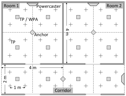
Each location is divided in four of two by two meters cells. At the center of the cell is an test location for the mobile node. Each room has four test locations. Every device is placed 1.0 m above the floor and they are all in line of sight from each other.
For every experiment that is done the following yields. The mobile node is placed at every testing location in room one and two and the corridor. On every test location the mobile node initiates 50 localization rounds. The localization period is set to 1.0 s and the transmit power of the Anchor and Mobile Node is set at the maximum of 4 dBm.
IV-A1 Experiment Scenarios
The following three experiments were performed.
Experiment 1: One Anchor Node is placed in the center of one room and the Mobile Node is placed at every testing location in room one and two and the corridor. As there is only one Anchor Node in the area we consider all packets decoded with this anchor ID correctly localized.
Experiment 2: Two Anchor Nodes are deployed, each in the center of room one and two. Two Voronoi cells around the Anchor Nodes are defined and if the Anchor Node is localized in the Voronoi cell that corresponds to the Anchor ID that is decoded we consider it as correctly localized.
Experiment 3: Three Anchor Nodes are deployed, each in the center of room one, two and the corridor. The Mobile Node is correct if the localization result is in the correct room. We make use of the fact that the walls attenuate the RF signals from the nRF51822 and that the signal range will adjust to the room layout accordingly.
IV-A2 Data Acquisition
As the Mobile Node is powered wirelessly interfacing with the nRF51822 would consume power which we then can not be used for localization. We overcome this problem by using a BLE USB dongle as a sniffer [11]. This sniffer monitors all packets sent by the Mobile Node. In our experiment the result of every localization round is send in the next localization round within the location-request packet. The sniffer then receives the data and saves it on to a text file on the PC for further data processing.
IV-B Experiment Results
For the evaluation of WiPLoc we introduce two metrics: accuracy and Packet Reception Rate (PRR). We define accuracy as follows. When the Mobile Node is localized in the room where it is currently located we count the localization as successful. When the Mobile Lode is localized to another room then where it is currently located it is counted as unsuccessful. PRR is defined as the number of location-request packets send by the mobile node divided by the number of received location-reply packets.
At every test location 50 localization rounds were performed. For each test location PRR and the accuracy is computed and averaged. The results are shown in Table II where the accuracy is normalized to the PRR. We observe that if the number of anchors deployed increases the PRR decreases. The accuracy also decreases when the number of anchors increases. The PRR decreasing is mostly due the fact of packet collisions. Nevertheless, even in the worst case (Experiment 3) we demonstrate that we achieve (i) extremely low power consumption for localization using collision packets, and (ii) accurate room-level localization for Mobile Node using only WPT energy.
| PRR (%) | Accuracy (%) | |
|---|---|---|
| Experiment 1 | 100 | 100 |
| Experiment 2 | 99.3 | 95.5 |
| Experiment 3 | 89.6 | 84.6 |
V WiPLoc++: Extending WiPLoc to Cell-Level Localization Accuracy
So far we have demonstrated how WiPLoc allows us to accurately localize items per room. The question is how to improve localization accuracy from room-level to cell-level.
V-A WiPLoc: Challenge of Cell-level Localization
WiPLoc is designed to cope with localization at a room-level ( 16 ) accuracy but does not allow to improve the accuracy further down. We shall describe specific problems of WiPLoc related to this functionality and propose our improvements, which we collectively shall denote as WiPLoc++.
Problem 1—Limited Energy for Synchronization
Referring again to Table I, we see the the power consumption of packet reception (26 mW) is above the limit of harvested power (0.8 mW at 3 m). Synchronization is needed when operating with multiple Anchor Nodes this requires idle listening continuously, However this is not possible if Anchor Nodes are required to operate under the harvested RF energy.
Solution to Problem 1: We propose a semi-passive wakeup scheme to allow Anchor Nodes listening to the synchronization signal only when there is a localization request. This solution will be described in Section V-B.
Problem 2—Scalability of WiPLoc
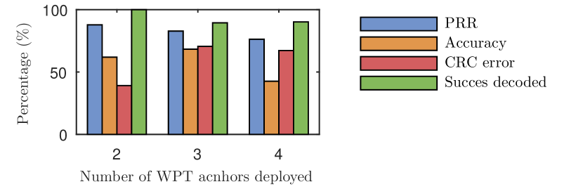
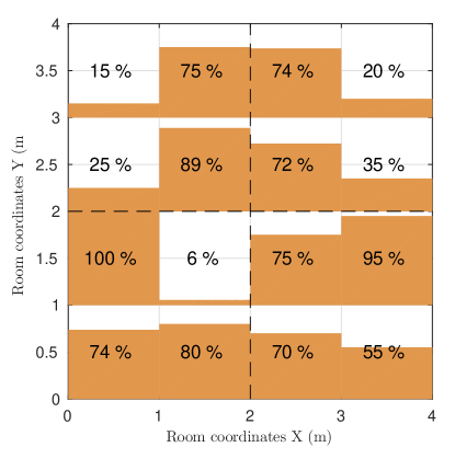
Normally, with more Anchor Nodes we obtain higher localization accuracy. To prove this assumption, we deploy 2, 3 and 4 Anchor Nodes, respectively, in room one and test the PRR and accuracy respectively. The deployment setup and localization testing positions are illustrated in Fig. 3(a) while the test results are shown in Fig. 4. The key observation is that the PRR and accuracy of cell-level localization decrease as the number of Anchor Nodes increase. This is mainly caused by the radio interference to the orthogonal code from multiple Anchor Nodes. It means that interference caused by multiple Anchor Nodes will limit the accuracy and scalability of WiPLoc in dense Anchor Nodes deployments.
Solution to Problem 2: We propose to restrict the number of Anchor Nodes used for cell-level localization by using WPT Receive Signal Strength (RSS) based distance estimation, which will be presented in Section V-C.
V-B ID Based Semi-Passive Wakeup
The collision based localization introduced in Section III requests the synchronization of packet transmission and reception among multiple nodes. The Anchor Node, also responsible for charging, has a fixed power supply, ergo enough energy to listen to the localization request and synchronization signal continuously. If we want to increase the number of Anchor Nodes without a fixed power supply, they also need to be be powered by wireless power.
V-B1 Extra Localization Component
Following from the above observation we introduce a new node aiding in localization.
-
•
Wirelessly-Powered Anchor Node (WPA): This node is the same as Anchor Node, however it operates purely based on harvested RF energy from the Anchor Node.
Energy harvested from Anchor Node is not enough for WPAs to listen to the synchronization signal continuously. Therefore, we propose ID based semi-passive wakeup approach to wakeup WPAs from sleeping mode only when the localization request is sent from Mobile Nodes. The method works as follows.
V-B2 Wakeup Process
As in WiPLoc, Anchor Nodes are deployed one per room and constantly switched on for wireless charging. Using the harvesting energy from neighbor Anchor Nodes, WPAs periodically wakeup from sleep mode and perform the measurement of the voltage of the harvested power with Analog to Digital Converter (ADC) port. Based on our measurements (see again Table I), the power consumption of ADC measurement ( 1.5 mW) is of the same magnitude as the harvested power (from 3.2 mW at 1 m to 0.79 mW at 3 m). Although the power consumption of ADC measurement is larger than harvested power at the distance of 3 m. We only conduct one ADC measurement every period and are in sleeping mode the rest of time. This ensures that the average power consumption low enough.
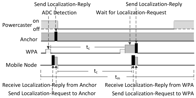
Now, suppose that the Mobile Node has initiated the room-level localization. Then Mobile Node broadcasts a localization request to the Anchor Nodes. The Anchor Node will send a location reply back and will send a passive wake up signal to all WPAs in the same room: switch off (the powercaster) charging for a short time and then switch back on again. Then the Anchor Node sends sleep commands to the WPAs that are required to stay a sleep for the cell-level localization.
At the WPA, Once a voltage falling of the harvested power is measured on , the WPA wakes up from sleeping mode and starts listening to radio packets. If the WPA does receive a sleep it keeps listening for a location-request from the Mobile Node.
Meanwhile, the Mobile Node received the location-reply from the Anchor Node and then waits for to broadcast the location-request to the WPAs. Then Mobile Node is localized based on the collision based localization approach as explained in Section III. The whole process is described in Algorithm 2.
It is worth noting that the wake up time of each WPA and Mobile Node have small differences. The main reason for that is the time for measuring the semi-passive wake up signal at each WPA is not synchronized. To guarantee that all WPAs can hear the localization synchronization signal from Mobile Node, all WPAs wakeup immediately after receiving the semi-passive wakeup signal and listen a maximal period of and sleep again if they receive nothing in that time frame.
V-B3 Optimization
Although the power consumption of ADC is much lower than receiving according to the measurement results in Table I, for efficiently using the limited WPT energy we optimize the ADC period to further decrease the total power consumption of WPA. Assume that WPAs are deployed around the semi-passive wakeup range of Anchor Node. The time that the semi-passive wakeup signal is detected by the ADC measurement at WPA is denoted as . After sending passive-wakeup-request to Anchor Node, the Mobile Node sleeps for and then sends localization-request. Then each WPAs are waken up and listen for . To simplify the analysis we assume that are independent and uniformly distributed in with CDF .
Proposition 1.
The value of producing minimum expected power consumption at WPA, , is
| (2) |
Proof.
The average power consumption of a WPA during a localization period is
| (3) |
where the expected time of waiting for interruption during is , where denotes the the number of ADC measurement during and , and denote time spent in ADC measurement, packet reception and transmission, respectively. To calculate recall that the expectation of is . Then the expected waiting time is .
As is discreet we replace it with a continuous value for estimating the range of the minimum value . The value of that minimizes the expectation of can be calculated as which results in (2). ∎
V-C Range Estimation using RSS of WPT Signal
The purpose of this component is to narrow down the possible location of the Mobile Node, and restrict the number of WPAs used for collision-based localization. We shall now justify the selection of the range estimation process.
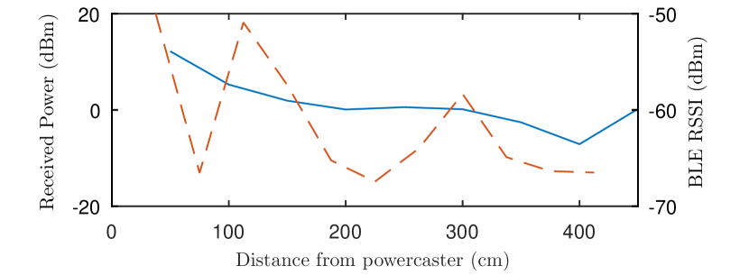
V-C1 Reason for Range Estimation using WPT RRS
We select range estimation using WPT RSS for two reasons: (i) the charging radio of WPT covers the localization area already, which does not require any additional communication component; (ii) Fig. 6 illustrates the voltage measurement results using ADC (at pin) for various distances. The figure also illustrates that the harvested power RSS is in much more stable then the RSS of the nRF51822 at the same distance. We take advantage the attenuation of voltage over distances to estimate whether the Mobile Node is inside or outside a requested range.
V-C2 Range Estimation Process
The RSS-based range estimation works as follows. Following the same deployment model as in Section V-B, we define the cell of WPA as , and the voltage measurement results using ADC of a Mobile Node and WPAs as and , respectively. The threshold RSS value, , is used to classify the cells of WPAs. The cells of WPAs are then categorized as (i) = , (ii) = , and (iii) .
The Mobile Node broadcasts a localization-request with . If an Anchor Node receives a localization-request it will compare with the threshold value . If , then the Anchor Node sends a semi-passive wakeup signal to WPAs in ; otherwise, it wakes up WPAs in for localization.
If the Mobile Node does receive a localization-reply from the WPAs, it will then request the Anchor Node to wake up the WPAs in other area for cell-level localization. The detailed process is presented in Algorithm 2.
V-C3 Discussion
We need to point to certain limitations of the WiPLoc++ localization.
-
1.
The value can calculated by . To simplify the implementation we use the pre-measured RSS dBm at the geographic middle position of the deployment area of WPAs around the Anchor Node. Such approach however might not be always practical.
-
2.
Values of and can be affected by obstacles between powercaster and WPA / Mobile Node, relative direction of antennas between charger and harvester, etc. Therefore WPT RSS-based range estimation can only be used for estimating the Mobile Node location with a coarse resolution.
-
3.
The transmission power of WPA messages is set to cover only the cell area which itself belongs to. If the Mobile Node is not inside the estimated range using , it may not receive a localization-reply from WPAs belonging to the estimated range. To compensate this case, Anchor Node wakes up the WPAs in the other area for the next round of localization.
Anchor Node (Fixed Powered Anchor Node):
WPA (Wireless Powered Anchor Node):
Mobile Node:
VI WiPLoc++: Implementation and Evaluation
We evaluate the overall performance of WipLoc++ through (i) PRR and localization accuracy (as in the case of WiPLoc) and (ii) the recharging period of WPA using harvested energy.
VI-A Hardware Implementation
To implement WiPLoc++ using existing WiPLoc hardware some modifications need to be made. We list them below.
-
•
Anchor Node: This node the nRF51822 is combined with the powercaster. A transistor is added to the power line of the powercaster so that the nRF51822 can control if the powercaster is on or off.
-
•
Mobile Node: There are no modification to the hardware of the mobile node but two extra connections are made between the nRF51822 and the harverster. The and the are connected to P0.01 and P0.02 of the nRF51822, respectively.
-
•
Wirelessly-Powered Anchor Node: This node uses the same combination of hardware and connections as the Mobile Node except for one difference. The development board for the nRF51822 is the Smart Beacon Kit and not the PCA10005.
All electrical connections of three nodes are given in Fig. 2.
VI-B Experiment Setup
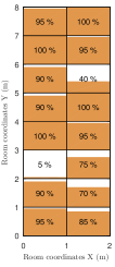
Due to the limited number of harvesters in our laboratory, we only deploy four WPAs around one Anchor Node. The cell-level localization experiments are performed in a room and corridor separately. The deployment of WPAs, Anchor Nodes in the rooms and the testing positions of Mobile Node are illustrated in Fig. 3(a). The Mobile Node sends 20 localization requests with period 1.0 s at each testing position. As the length of the corridor is larger than the effective charging range from Anchor Node to WPA we deploy two powercasters back-to-back in the middle of the corridor pointing to the begin and the end of the corridor, respectively.
VI-C Experiment Results
| PRR (%) | Accuracy (%) | |
|---|---|---|
| Room | 97.5 | 59.9 |
| Corridor | 100 | 82.2 |
Compared with the WiPLoc room-level results, (see Table II), the average cell-level PRR and localization accuracy of WiPLoc++ in the room and corridor (see Table III) are on the same level. Although the cell-level localization accuracy in the room is lower than the room-level accuracy, the localization cell is only 4 using WiPLoc++, which is much smaller than the 16 localization room using WiPLoc. The test results prove that WiPLoc++ is able to achieve cell-level localization using WPT in all deployed nodes except the Anchor Node.
On the other hand, we find that cell-level localization accuracy at some positions in Fig. 7 is much lower than the average value for the whole area. This is due to two reasons: (i) the radio pattern of powercaster has only 60∘ coverage in width and height, therefore some testing positions at the border of the room are not effectively covered and (ii) the threshold value uses the measured RSS value at the middle position of the charging area. However, the contour line of is not straight in the radio pattern of powercaster, which makes it difficult to categorize cells into strict squares.
VII Conclusion
In this paper we presented an RF WPT-enabled indoor localization system denoted as WiPLoc (Wireless Powered Localization system). The key innovations of WipLoc include: (i) leveraging collisions and orthogonal codes to build an extremely low power localization approach, and (ii) constructing a cell-level localization network by managing the limited harvested energy from RF-based WPT systems. Based on extensive indoor experiments, we showed that WiPLoc is capable of providing continuous cell-level localization to mobile nodes. To the best of our knowledge, WiPLoc is the first localization system powered by RF transmission.
References
- [1] Y. Gu, A. Lo, and I. Niemegeers, “A survey of indoor positioning systems for wireless personal networks,” IEEE Commun. & Surveys Tuts., vol. 11, no. 1, pp. 13–32, First Quarter 2009.
- [2] D. Lymberopoulos, J. Liu, X. Yang, R. R. Choudhury, V. Handziski, and S. Sen, “A realistic evaluation and comparison of indoor location technologies: Experiences and lessons learned,” in Proc. ACM IPSN, Seattle, WA, USA, Apr. 14–16 2015.
- [3] P. Lazik, N. Rajagopal, O. Shih, B. Sinopoli, and A. Rowe, “ALPS: A bluetooth and ultrasound platform for mapping and localization,” in Proc. ACM SenSys, Seoul, South Korea, Nov. 1–4 2015.
- [4] A. de Moes, Dec. 2015, personal communication.
- [5] L. Xie, Y. Shi, Y. T. Hou, and W. Lou, “Wireless power transfer and applications to sensor networks,” IEEE Wireless Commun., vol. 20, no. 9, pp. 140–145, Aug. 2013.
- [6] L. Xiao, P. Wang, D. Niyato, D. Kim, and Z. Han, “Wireless networks with rf energy harvesting: A contemporary survey,” IEEE Commun. Surveys Tuts., vol. 17, no. 2, pp. 757–789, Nov. 2014.
- [7] S. S. Saab and Z. S. Nakad, “A standalone RFID indoor positioning system using passive tags,” IEEE Trans. Ind. Electron., vol. 58, no. 5, pp. 1961–1970, Jul. 2011.
- [8] Q. Liu, M. Goliński, P. Pawełczak, and M. E. Warnier, “Green wireless power transfer networks,” Delft University of Technology, Delft, the Netherlands, Tech. Rep. TUD-01-2015, 2015. [Online]. Available: http://www.es.ewi.tudelft.nl/reports/ES-2015-01.pdf
- [9] L. Yang, Y. Chen, X.-Y. Li, C. Xiao, M. Li, and Y. Liu, “Tagoram: Real-time tracking of mobile rfid tags to high precision using COTS devices,” in Proc. ACM MobiCom, Hawaii, USA, Sep. 7–11 2014.
- [10] Powercast Corp., “Power harvesters and receivers,” 2015. [Online]. Available: http://www.powercastco.com/products/powerharvester-receivers
- [11] Nordic Semiconductor, “Bluetooth low energy products,” 2015. [Online]. Available: https://www.nordicsemi.com/eng/Products/Bluetooth-Smart-Bluetooth-low-energy
- [12] Y. Shu, P. Cheng, Y. Gu, J. Chen, and T. He, “TOC: Localizing wireless rechargeable sensors with time of charge,” in Proc. IEEE INFOCOM, Toronto, ON, Canada, Apr. 27 – May 2, 2014.
- [13] L. M. Ni, D. Zhang, and M. R. Souryal, “RFID-based localization and tracking technologies,” IEEE Wireless Commun., vol. 18, no. 2, pp. 45–51, Apr. 2011.
- [14] W. Zhu, J. Cao, Y. Xu, L. Yang, and J. Kong, “Fault-tolerant rfid reader localization based on passive rfid tags,” IEEE Trans. Parallel Distrib. Syst., vol. 25, no. 8, pp. 2065–2076, Aug. 2014.
- [15] L. M. Ni, Y. Liu, Y. C. Lau, and A. P. Patil, “LANDMARC: indoor location sensing using active RFID,” Springer Wireless Networks, vol. 10, no. 6, pp. 701–710, Nov. 2004.
- [16] Y. Liu, Y. Zhao, L. Chen, J. Pei, and J. Han, “Mining frequent trajectory patterns for activity monitoring using radio frequency tag arrays,” IEEE Trans. Parallel Distrib. Syst., vol. 23, no. 11, pp. 2138–2149, Dec. 2011.
- [17] H. Liu, H. Darabi, P. Banerjee, and J. Liu, “Survey of wireless indoor positioning techniques and systems,” IEEE Trans. Syst., Man, Cybern. C, Appl. Rev., vol. 37, no. 6, pp. 1067–1080, Nov. 2007.
- [18] J. C. Arnbak and W. van Blitterswijk, “Capacity of slotted aloha in rayleigh-fading channels,” IEEE J. Sel. Areas Commun., vol. 5, no. 2, pp. 261–269, Feb. 1987.
- [19] J. van Velzen and M. Zuniga, “Let’s collide to localize: Achieving indoor localization with packet collisions,” in Proc. IEEE PerCom Workshop, San Diego, CA, USA, Mar. 18–22 2013.
- [20] J. E. MacDonald, “Design methods for maximum minimum-distance error correcting codes,” IBM Journal of Research and Development, vol. 4, no. 1, pp. 43–57, Jan. 1960.
- [21] Qingzhi Liu, Wieger IJntema, Anass Drif, Przemysław Pawełczak, and Marco Zuniga, “Source code of the software accompanying this submission,” 2015. [Online]. Available: http://bit.ly/1PaTcZk
- [22] C. Cirstea, T. Petrita, V. Popescu, and A. Gontean, “Performance analysis and modelling of a radio frequency energy harvesting system,” Advances in Electrical and Computer Engineering, vol. 13, no. 1, pp. 27–32, Feb. 2013.
- [23] (2014) Monsoon Power Monitor Homepage. [Online]. Available: http://www.msoon.com/LabEquipment/PowerMonitor/