Nanoparticle detection in an open-access silicon microcavity
Abstract
We report on the detection of free nanoparticles in a micromachined, open-access Fabry-Pérot microcavity. With a mirror separation of 130m, a radius of curvature of 1.3 mm, and a beam waist of m, the mode volume of our symmetric infrared cavity is smaller than 15 pL. The small beam waist, together with a finesse exceeding 34,000, enables the detection of nano-scale dielectric particles in high vacuum. This device allows monitoring of the motion of individual 150 nm radius silica nanospheres in real time. We observe strong coupling between the particles and the cavity field, a precondition for optomechanical control. We discuss the prospects for optical cooling and detection of dielectric particles smaller than nm in radius and amu in mass.
Optical microcavities recirculate and strongly confine light, thereby enhancing the interaction between light and matter Vahala03 ; Zhi17 . Small mode volume cavities have been coupled to single atoms Aoki06 ; Trupke07 , Bose-Einstein condensates Colombe07 , organic molecules Toninelli10 , quantum dots Barbour11 , and nitrogen vacancy centers Albrecht13 . Whispering gallery mode (WGM) resonators can be used to detect and characterize label-free molecules Vollmer02 , single viruses Vollmer08 , aerosol-particles Zhu10 and particles with radii of a few tens of nanometers Lu11 ; Li14 when the specimen is adsorbed onto the resonator. Similar results have been achieved in photonic crystal cavities Lee07 ; Quan13 ; Liang15 and nanoplasmonic-photonic hybrid microcavities Dantham13 .
In recent years, a growing number of research groups have utilized optical cavities to control the motion of dielectric nanoparticles Kiesel13 ; Asenbaum13 ; Millen15 . Cavity-mediated quantum ground state cooling is predicted to be within reach for both their centre of mass motion Chang10 ; Romero-Isart10 ; Barker10 and their rotational degrees of freedom Stickler16 ; Hoang16 . Cold, free particles in high vacuum are considered excellent candidates for matter-wave interferometry Arndt14 ; Bateman14 , in a mass range where limits to established quantum theory may be explored Ghirardi90 ; Diosi87 ; Ghirardi90a ; Penrose96 . The coupling of nanoparticles to a cavity field can be increased by exploiting the shape-enhanced polarizability of non-spherical particles Kuhn15 ; Kosloff16 , and by reducing the mode volume of the cavity. Bulk optical cavities are typically limited to beam waist radii larger than m, due to limitations on the radii of curvature of the cavity mirrors.
Here, we present the detection of free nanoparticles in transit through a chip-based, high finesse, open-access silicon Fabry-Pérot microcavity, with a 15 pL mode volume. We detect the motion of the particles via the transmitted cavity light, and extract their velocity. Such gas-phase detection and characterization is advantageous in many fields, such as aerosol physics, nanoparticle synthesis and nanoparticulate exposure studies. In addition, we observe strong coupling between a nanoparticle and the optical field, which is of utmost importance for efficient optomechanical cooling.
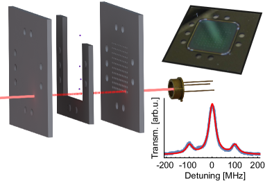
The method for fabricating and characterizing the silicon microcavities will be explained in detail elsewhere. Briefly, two silicon chips, which are the mirror image of each other, are patterned with an array of 100 mirrors with radii of curvature ranging from m to 1.4 mm. They are separated by a m thick, silicon spacer, as illustrated in Fig. 1, which lithographically pre-aligns the cavities. The total length of the individual cavities depends in addition on the depth of the mirrors. The mirror chips are coated with a high reflectivity, multilayer dielectric coating (Advanced Thin Films, target transmission of 15 ppm). A single cavity, exhibiting sufficiently high finesse, is pumped with 25 mW at a wavelength of 1547 nm (Toptica CTL-1550) to excite a TEM00 mode, and the laser frequency is stabilized to the cavity resonance via side-of-fringe locking using the back-reflected beam. Here, we use an optical cavity with a length m, a free spectral range THz, a mode coupling of 30, mirror radius of curvature mm, a mode waist (radius) m, a decay rate MHz, and a finesse of . This yields a mode volume pL or , and an on-resonance intracavity intensity at the waist of approximately Wcm-2. The cavity finesse is limited by the deviation of the mirror shape from an ideal parabolic profile, and can be improved by optimization of the fabrication parameters Kleckner2010 .
Silica nanoparticles (Bangs Laboratories) of radius nm are launched through the cavity field at a pressure of mbar, using Laser Induced Acoustic Desorption Kuhn15 ; Millen16 . To detect the nanoparticles, the cavity input light is detuned from resonance by , and the transmitted light is monitored on a photodiode. The presence of a dielectric particle inside the cavity mode effectively increases the optical path length, thus shifting the cavity towards resonance and increasing the amount of light transmitted through the mirrors. The particle also scatters light out of the cavity mode, decreasing the amount of light transmitted. A net increase of the transmitted signal is a clear sign of strong, dispersive coupling between the particle and the cavity field Aspelmeyer14 . This allows the detection of particles with a signal-to-noise ratio (SNR) of more than 35, enabling detection of silica particles as small as 50 nm in radius.
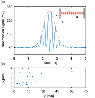
An example nanoparticle transit is shown in Fig. 2a. As the particle traverses the optical mode in the -direction i.e. perpendicular to the optical axis of the cavity, the transmitted signal increases with a Gaussian envelope (red dotted line), directly mirroring the Gaussian waist of the microcavity mode. Since is known from the cavity geometry, we can extract the velocity in the -direction, ms-1. There is also a fast modulation of the signal, as the nanoparticle crosses the optical standing-wave in the -direction. Since the wavelength of the light is known, we can extract the velocity in the -direction, ms-1. There is a slight decrease in signal below the baseline level in Fig. 2a, which is due to the particle scattering light from the cavity mode. In total, the particle dispersively shifts the cavity resonance by more than , confirming strong coupling between the particle and the cavity field. The extracted velocities for 19 nanoparticles are shown in Fig. 2b.
We now consider one specific application of such microcavities, namely their use for the optomechanical cooling of dielectric nanoparticles Horak97 ; Vuletic00 ; Chang10 ; Romero-Isart10 ; Barker10 ; Kiesel13 ; Asenbaum13 ; Millen15 . Cooling is believed to be necessary, for instance, to enable matter-wave interferometry with nanoscale objects Arndt14 ; Bateman14 . In particular, we will consider cooling of silicon nanoparticles due to their favourable dielectric properties Asenbaum13 , their applicability for nanofabrication Kosloff16 and their compatibility with optical ionization gratings Reiger06 . Such experiments are challenging at high mass, since the short de Broglie wavelength of a massive object requires a long interferometer. For a given resolution in the interference pattern on the detector screen, the required flight time through the interferometer scales linearly with the particle mass Note (1), limiting the mass to the amu range Bateman14 i.e. silicon spheres of 6-12 nm radius. Such small particles cannot be cooled in macroscopic cavities.
For optimal cooling the following criteria must be met: A) Operating in the regime of strong coupling, i.e. the dispersive frequency shift of the cavity resonance induced by the particle
| (1) |
(laser frequency and relative permittivity of the particle ) is larger than the cavity decay rate . B) Working in the resolved side-band limit to ensure that the response of the cavity field amplitude is retarded relative to the motion of the particle. Therefore, the axial mechanical trapping frequency of the particle
| (2) |
(wave-vector of the cavity field , intra-cavity power and particle density ) needs to be larger than . In order to cool small masses, the following cavity parameters can be optimized: finesse , beam waist radius
| (3) |
via and , and the intra-cavity power .
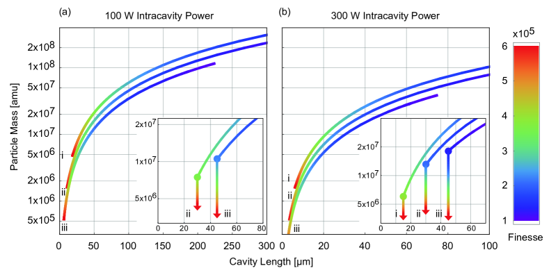
The parameter-space for optimal cooling is displayed in Fig. 3. The coloring of the curves indicates the minimum finesse, for a given ratio and intra-cavity power, required to fulfill conditions A & B. This finesse, in turn, sets the minimal mass that can be cooled for the given set of geometrical constraints. Increasing the mass does not allow for a reduction in finesse due to condition B. At a given , however, the minimum mass can be decreased by improving the finesse, as shown in the insets of Fig. 3. We consider fixed ratios of i) 0.5, ii) 1.0 Note (2), and iii) 1.5, and intra-cavity powers of a) 100 W and b) 300 W. Hence, by moving to smaller cavities with higher finesse Derntl14 (, m, m, W) it will be possible to cool silicon nanoparticles with masses below amu, corresponding to a sphere of radius 12 nm. Assuming the same SNR as presented here, optimized microcavities could detect particles down to 5 nm in radius.
In conclusion, we present the detection of free nanoparticles in an open-access silicon microcavity. We observe their transit via the transmitted cavity light, extract their velocity, and observe strong coupling between the particle and intracavity field. Such a system will be useful for optomechanics, and for characterization and detection of nanoparticles, bio-molecules, viruses, and aerosols. With further improvements, this microcavity system will enable cavity cooling of a diverse range of sub -10 nm particles, which are suitable for matter-wave interferometry in a hitherto unexplored mass range of amu.
Acknowledgments
We are grateful for financial support by the Austrian Science Fund (FWF) through the projects P27297, “SiC-EiC”, DK-CoQuS (W1210) and DK-Solids4Fun (W1243). We further acknowledge funding from the Vienna University of Technology research funds. JM acknowledges funding from the European Union’s Horizon 2020 research and innovation programme under the Marie Skłodowska-Curie grant agreement No 654532.
References
- (1) K. Vahala, Nature 424, 839–846 (2003).
- (2) Y. Zhi, X.-C. Yu, Q. Gong, L. Yang, Y.-F. Xiao, Adv. Mater. 29, 1604920 (2017).
- (3) T. Aoki, B. Dayan, E. Wilcut, W.P. Bowen, A.S. Parkins, T.J. Kippenberg, K.J. Vahala and H.J. Kimble, Nature 443, 671–674 (2006).
- (4) M. Trupke, J. Goldwin, B. Darquie, G. Dutier, S. Eriksson, J. Ashmore and E. A. Hinds, Phys. Rev. Lett. 99, 063601 (2007).
- (5) Y. Colombe, T. Steinmetz, G. Dubois, F. Linke, D. Hunger and J. Reichel, Nature 450, 272–276 (2007).
- (6) C. Toninelli, Y. Delley, T. Stöferle, A. Renn, S. Götzinger and V. Sandoghdar, Appl. Phys. Lett. 97, 021107 (2010).
- (7) R.J. Barbour, P.A. Dalgarno, A. Curran, K.M. Nowak, H.J. Baker, D.R. Hall, N.G. Stoltz, P. M. Petroff and R.J. Warburton, J. Appl. Phys. 110, 053107 (2011).
- (8) R. Albrecht, A. Bommer, C. Deutsch, J. Reichel and C. Becher, Phys. Rev. Lett. 110, 243602 (2013).
- (9) F. Vollmer, D. Braun, A. Libchaber, M. Khoshsima, I. Teraoka and S. Arnold, Appl. Phys. Lett. 80, 4057–4059 (2002).
- (10) F. Vollmer, S. Arnold and D. Keng, Proc. Natl. Acad. Sci. USA 105, 2071–20704 (2008).
- (11) J. Zhu, S.K. Ozdemir, Y.-F. Xiao, L. Li, L. He, D.-R. Chen and L. Yang, Nature Photon. 4, 46–49 (2010).
- (12) T. Lu, H. Lee, T. Chen, S. Herchak, J.-H. Kim, S. E. Fraser, R. C. Flagan and K. Vahala, Proc. Natl. Acad. Sci. USA 108, 5976–5979 (2011).
- (13) B.-B. Li, W. R. Clements, X.-C. Yu, K. Shi, Q. Gong, Y.-F. Xiao, Proc. Natl. Acad. Sci. USA 111, 14657–14662 (2014).
- (14) M.R. Lee and P.M. Fauchet, Opt. Lett. 32, 3284–3286 (2007).
- (15) Q. Quan, D.L. Floyd, I.B. Burgess, P.B. Deotare, I.W. Frank, S.K.Y. Tang, R. Ilic and M. Loncar, Op. Express 21, 32225–32233 (2013).
- (16) F. Liang and Q. Quan, ACS Photonics 2, 1692–1697 (2015).
- (17) V.R. Dantham, S. Holler, C. Barbre, D. Keng, V. Kolchenko and S. Arnold, Nano Lett. 13, 3347–3351 (2013).
- (18) N. Kiesel, F. Blaser, U. Delic, D. Grass, R. Kaltenbaek, and M. Aspelmeyer, Proc. Natl. Acad. Sci. USA 110, 14180 – 14185 (2013).
- (19) P. Asenbaum, S. Kuhn, S. Nimmrichter, U. Sezer, and M. Arndt, Nat. Commun. 4, 2743 (2013).
- (20) J. Millen, P. Z. G. Fonseca, T. Mavrogordatos, T. S. Monteiro, and P. F. Barker, Phys. Rev. Lett. 114, 123602 (2015).
- (21) D. E. Chang, C. A. Regal, S. B. Papp, D. J. Wilson, J. Ye, O. Painter, H. J. Kimble and P. Zoller, Proc. Natl. Acad. Sci. 107, 1005–1010 (2010).
- (22) O. Romero-Isart, M. Juan, R. Quidant, and J. Cirac, New J. Phys. 12, 033015 (2010).
- (23) P.F. Barker and M.N. Schneider, Phys. Rev. A 81, 023826 (2010).
- (24) B. A. Stickler, S. Nimmrichter, L. Martinetz, S. Kuhn, M. Arndt and K. Hornberger, Phys. Rev. A 94, 033818 (2016).
- (25) T.M. Hoang, Y. Ma, J. Ahn, J. Bang, F. Robicheaux, Z.-Q. Yin, and T. Li, Phys. Rev. Lett. 117, 123604 (2016).
- (26) M. Arndt and K. Hornberger, Nature Phys. 10, 271–277 (2014).
- (27) J. Bateman, S. Nimmrichter, K. Hornberger, and H. Ulbricht, Nat. Commun. 5, 4788 (2014).
- (28) G. C. Ghirardi, P. Pearle, and A. Rimini, Phys. Rev. A 42, 78 – 89 (1990).
- (29) L. Diósi, Phys. Lett. A 120, 377–381 (1987).
- (30) G. C. Ghirardi, R. Grassi, and A. Rimini, Phys. Rev. A 42, 1057 – 1064 (1990).
- (31) R. Penrose, Gen. Rel. Grav. 28, 581–600 (1996).
- (32) S. Kuhn, P. Asenbaum, A. Kosloff, M. Sclafani, B. A. Stickler, S. Nimmrichter, K. Hornberger, O. Cheshnovsky, F. Patolsky, and M. Arndt, Nano Lett. 15, 5604–5608 (2015).
- (33) A. Kosloff, O. Heifler, E. Granot and F. Patolsky, Nano Lett. 16, 6960–6966 (2016).
- (34) D. Kleckner, W.T.M. Irvine,S.S.R. Oemrawsingh and D. Bouwmeester, Phys. Rev. A 81, 043814 (2010).
- (35) J. Millen, S. Kuhn, F. Patolsky, A. Kosloff and M. Arndt, Proc. SPIE 9922, 99220C (2016).
- (36) M. Aspelmeyer, T. J. Kippenberg, and F. Marquardt, Rev. Mod. Phys. 86, 1391–1452 (2014).
- (37) P. Horak, G. Hechenblaikner, K. Gheri, H. Stecher and H. Ritsch, Phys. Rev. Lett. 79, 4974–4977 (1997).
- (38) V. Vuletic and S. Chu, Phys. Rev. Lett. 84, 3787–3790 (2000).
- (39) E. Reiger, L. Hackermüller, M. Berninger and M. Arndt, Opt. Commun. 264, 326–332 (2006).
- (40) R. Kaltenbaek, M. Aspelmeyer, P. F. Barker, A. Bassi, J. Bateman, K. Bongs, S. Bose, C. Braxmaier, Č. Brukner, B. Christophe, et al., EPJ Quant. Tech. 3, 5 (2015).
- (41) O. Romero-Isart, New J. Phys., accepted (2017).
- (42) S. Nimmrichter, K. Hammerer, P. Asenbaum, H. Ritsch and M. Arndt New J. Phys. 12, 083003 (2010).
- (43) C. Derntl, M. Schneider, J. Schalko, A. Bittner, J. Schmiedmayer, U. Schmid and M. Trupke, Opt. Express 22, 22111 (2014).
- Note (1) \BibitemOpenThere are proposals to overcome this limitation by operating in a zero-g environment Kaltenbaek15 or with magnetically levitated superconductors Romero-Isart17 .\BibitemShutStop
- Note (2) \BibitemOpenThe influence of frequency-degenerate higher-order transverse modes Nimmrichter10 can be neglected due to the finite extent of the mirrors, which only support low order modes.\BibitemShutStop