Phase sensitive imaging of 10 GHz vibrations in an AlN microdisk resonator
Abstract
We demonstrate a high frequency phase-sensitive heterodyne vibrometer, operating up to 10 GHz. Using this heterodyne vibrometer, the amplitude and phase fields of the fundamental thickness mode, the radial fundamental and the 2nd-order modes of an AlN optomechanical microdisk resonator are mapped with a displacement sensitivity of around . The simultaneous amplitude and phase measurement allows precise mode identification and characterization. The recorded modal frequencies and profiles are consistent with numerical simulations. This vibrometer will be of great significance for the development of high frequency mechanical devices.
Electromechanical and optomechanical resonators have played important roles in a variety of quantum and classical applications (Appli1, ; Appli2, ; Appli3, ), including ground-state cooling of mechanical resonators (Cool1, ; Cool2, ; Cool3, ), strong coupling between mechanical oscillator and microwave/optical resonators (strong1, ; strong2, ; strong3, ), efficient conversion between photons at vastly different frequencies (Conversion1, ; Conversion2, ), and non-reciprocal optomechanical devices (Nonreciprocity1, ; Nonreciprocity2, ; Nonreciprocity3, ). Particularly, high frequency mechanical devices above 10 GHz are desirable for advancing mechanical quantum devices because they require less stringent refrigeration conditions for reaching quantum mechanical ground state and their frequency are matched to superconducting quantum circuits (10GHzImprotant, ). A 10 GHz mechanical oscillator can be cooled to ground state by direct dilution refrigeration without the necessity of active cooling techniques. Furthermore, the extension of acoustic resonators to microwave X-band and beyond is important for next generation wireless communications (book1, ; communication1, ; MoLi1, ; MoLi2, ).
The characterization of vibrational modes of electro/optomechanical devices, including identification of the vibration frequencies, profiles, mode losses and so on, is important for validating their design, operation and performance. Scanning optical vibrometer enable high-resolution, non-invasive mapping of the vibration pattern of acoustic devices(Vib1SAW, ; Vib2thin, ; Vib3thin, ; Timeresolved1, ; VibConfocal, ; Vib4Canti, ; Vib5drump, ; Vib6thin, ; Timeresolved2, ; Vib7Canti, ; Vib8thin, ; Vib9drump, ; VibSiC, ; Vibwaveguide, ; Vibring, ). It also offers complete quadrature information rather than pure intensity response. Optical vibrometers have proven their strength in the researches and applications of microacoustic components, including thin film resonators (Vib2thin, ; Vib3thin, ; Vib6thin, ; Timeresolved2, ; Vib8thin, ), piezoelectric microcantilevers (Vib4Canti, ; Vib7Canti, ), silicon carbide microdisk resonators (VibSiC, ), surface acoustic resonators and waveguides on a chip (Vibwaveguide, ; Vibring, ). Optical pump-probe technique, which requires high-performance pulsed laser, allows the time-domain response of mechanical oscillators to be measured (Timeresolved1, ; Timeresolved2, ; Timeresolved3, ; Timeresolved4, ). Frequency-domain measurements with continuous laser, as a complementary method, is often used to characterize mechanical resonators with high quality () factors. However, the frequencies of the vibration modes mapped by this method are limited to a few gigahertz (Vib2thin, ; Vib3thin, ; Vib6thin, ; Vib8thin, ). Here we demonstrate a scanning heterodyne vibrometer for realizing simultaneous absolute amplitude and phase imaging of vibration up to 10 GHz-range in an AlN microdisk resonator with a displacement sensitivity of for out-of-plane motion detection. Measurements on the fundamental thickness mode, the fundamental radial mode and the 2nd-order radial modes of an AlN microdisk provide phase-sensitive modal visualization that is consistent with our numerical simulation.
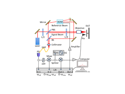
The vibrometer derives the vibration from the modulated light signal by a heterodyne interoferometer. The experimental setup is shown in Fig. 1. A similar setup has also been realized and described in detail by Martinussen et al. (Vib5drump, ), Kokkonen and Kaivola (Vib6thin, ), and Leirset et al. (Vib9drump, ). A linearly polarized 633 nm HeNe laser is split into two paths - the reference beam and the probe beam - by a polarizing beam splitter (PBS). A half-wave plate () is used to tune the power ratio between the reference and the probe beams. The frequency of the reference beam is shifted from the original input laser frequency to by an acousto-optic modulator (AOM). The probe beam is focused perpendicularly onto the sample with a microscope objective (NA ) and reflected back to the PBS. The polarization of the reflected probe signal is rotated by 90 degrees because of the double pass through the plate, which leads to the same polarization as the frequency-shifted reference light. Then the motion-modulated probe and reference light are combined with the beam splitter and sent into a photodetector (PD) through a single mode fiber. The fiber acts as a confocal pinhole to increase the lateral resolution (VibConfocal, ). The theoretical resolution limit in our setup is around 600 nm () as described in Ref. 24.
To analyze the heterodyne signal, we consider the sample surface vibrating sinusoidally as in the z-direction (perpendicular to the surface of sample), where , and are the amplitude, angular frequency and phase of the vibration, respectively. The probe light field detected by the PD is and the reference light field is , where () and () denote the amplitudes and phases of the probe (reference) field, and is the optical wavenumber. When , the can be expanded to the first order of as
| (1) | |||||
The PD response to the intensity of light field is
| (2) | |||||
where is the responsivity of the PD. Here, we have dropped the second-order term of and also filtered out the component oscillating at high frequency . When the lock-in amplifier (LIA) demodulates at and simultaneously, the amplitude () and phase () of the reference (signal) component are determined. Then, the amplitude and the phase of the surface vibration can be calculated as , .
In our experiment, the frequency of signal should be mixed with a signal generator (SG) to a lower frequency that falls within the frequency operation range of the lock-in amplifier LIA (Zurich instruments UHFLI), i.e., less than 600 MHz. Therefore, the detector signal from the PD (Newport, 1580-A, 12 GHz) is split by a power splitter with one of the outputs sent through a high-pass filter (HPF) to filter out the reference component, then mixed down to the new frequency , where denotes the operating frequency of the SG. The mixer output is fed into the LIA and demodulated at . The amplitude of demodulation signal is , where is a conversion factor determined by the conversion loss of mixer, insertion loss of HPF and coaxial cables, and imbalance of the power splitter. It should be pointed out that this conversion factor is non-constant when we measure different mechanical modes in the AlN microdisk due to the frequency-dependent response of electronic components. For the measurement at around 10.4 GHz, 1.67 GHz and 635 MHz as will be described below, is around , and , respectively. The signal output 1 of LIA is set at and mixed with the SG to actuate the device using a dipolar pin antenna. The signal output 2 of LIA is used to drive the AOM. The SG is clock-referenced to the LIA to ensure that they are phase locked. The device under test is placed on a linear piezo stage (Micronix PPS-20) with lateral resolution of , which allows two-dimensional point-by-point scanning.
Here, we focus on the noise analysis for the measurement frequency around 10.4 GHz. The displacement sensitivity is defined as the normalized minimum detectable vibration amplitude , where (around ) is measured by the LIA and is the total noise. includes contribution from all available noise sources: electrical noise (noise without light input) from the PD, shot noise due to the discrete nature of photon, and the noise from other electrical parts (including LIA, amplifier and so on). With the PD connected, and with no incident light, the PD noise is measured as , which corresponds to a measurement sensitivity . The shot noise is given by , where is the elementary charge, the incident laser power on the PD, the detection bandwidth, and the gain of build-in transimpedance amplifier of the PD (ShotNoise, ). In our measurements, , , , and . The prefactor is attributed to the voltage division between the output impedance of the PD and the input impedance of the LIA. Therefore, the resulting shot-noise limited sensitivity becomes . The sum of electrical noise from the PD and the shot noise () gives a theoretical sensitivity limit of , which is close to our measured value . The above analysis shows that the PD noise is the dominant noise source. For the measurement frequency of 1.67 GHz and 635 MHz, the sensitivity is around , which is consistent with the above conclusion.
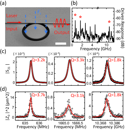
Figure 2(a) shows the SEM image of the device. A suspended c-axis-oriented AlN microdisk with radius and thickness 550 nm is fabricated adjacent to an optical waveguide. The radius of the supporting pedestal is controlled to be around 100 nm. The photonic structure is patterned using the two-step e-beam lithography and dry etching technique (Fabdisk, ; XuNJPpaper, ; Xu10GHzdisk, ). We actuate the microdisk piezoelectrically using a dipolar pin antenna and read out the mechanical motion optically through measuring the optical transmission signal of the optical whispering-gallery mode (Fig. 2(a)). This procedure is described in detail in Ref. 40. Figure 2(b) shows a broad-band driven response spectrum. The radial modes can be distinctly identified up to the 5th-order at 4.5 GHz and the fundamental thickness mode at 10.37 GHz. Zoomed-in spectra of three modes (indicated by the red stars in Fig. 2(b)) are shown in Fig. 2(c). The quality () factors measured are fitted to be around 3200, 3300 and 1800, respectively.
Figure 2(d) shows the frequency responses obtained by our heterodyne interferometer where the probe laser spot is focused on the center of the microdisk and the signal generator operating frequency is scanned with a fixed electric excitation of around 25 dBm for the fundamental and 2nd-order radial modes and 20 dBm for fundamental thickness mode. As shown in Fig. 2(d), the vibrometer measurements generally agree with optomechanically-transduced responses in Fig. 2(c). Due to reduced out-of-plane displacement, the third-order and above radial modes are not detected using our heterodyne interferometer.
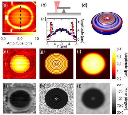
The demodulated two-dimensional (2D, ) vibration amplitude () and phase () data of the fundamental thickness mode (10.37 GHz) are presented in Figs. 3(a) and 3(f). The strong signal at the edge of the microdisk is due to the multi-path interference of light bouncing back at different sample heights. As illustrated in Fig. 3(b), when the laser spot is fixed at this position, the probe light field became , where the and denote the amplitude and phase of the reflected probe field by the silicon substrate. The demodulated signal of LIA is determined by the relative phase , as well as and . The phase depends on the structural parameters (2.2--thick buffer layer, 550-nm-thick microdisk) and () can be directly measured in the experiment. Such effect has also been described in detail by Rembe and Dräbenstedt (VibConfocal, ). As shown by the red line in Fig. 3(c), the fitting by considering this edge effect agrees well with the experiment results (black dots). Figure 3(e) plots the error-filtered amplitude image of Fig. 3(a). Similar analyses are performed for the other vibration modes discussed later in this paper. Figure 3(d) displays the simulated thickness mode shape using the three-dimensional finite-element method (COMSOL Multiphysics). For the out-of-plane motion (perpendicular to the surface of microdisk), multi-turn concentric rings are found in the amplitude distribution field, while the phase field is uniform except the center where the pillar supports the microdisk, as shown in Figs. 3(g) and 3(h), respectively. Because of the limited lateral resolution (around 900 nm for our setup), the spatial images we detect are the convolution transformation of the vibration fields, as shown in Figs. 3(i) and 3(j). The convolution transformation formula is , where is the radius of the Gaussian-shape spot, is the expected displacement of measurement, is the simulated displacement, and 0.57 is the normalization factor. The simulated convolution images of amplitude and phase response match well the experiment results.
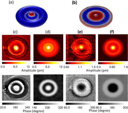
Figures 4(a) and 4(b) show the simulated patterns of the fundamental and the second-order radial modes, whose resonant frequencies are 635 MHz and 1.6 GHz, respectively. The measured amplitude and phase fields are plotted in Figs. 4(c) and 4(e) with the simulated of out-of-plane motion shown in Figs. 4(d) and 4(f). Benefiting from the 2D images of acoustic field distribution, especially the phase information, we can identify the observed modes unambiguously. For both vibrational modes, the energy of out-of-plane motion concentrates in the central part of the mcirodisk, we can speculate that the elastic wave leakage at the pedestal will induce significant mechanical loss for radial modes. Therefore, reducing the size of the supporting pedestal can improve the factor of the mechanical modes. Simulation results show that the factors are proportional to for the fundamental radial mode and for the second-order radial mode, respectively, where is the surface area of the supporting pedestal.
In conclusion, we have developed a high frequency scanning heterodyne vibrometer, which can measure the mechanical motion up to 10 GHz. It not only produces high-resolution amplitude distribution of the vibration modes but also clearly maps out the phase of the vibration. This unique capability allows us to fully characterize the thickness mode and radial modes supported by the AlN microdisk and make accurate comparisons with numerical simulations. The phase-sensitive heterodyne vibrometer demonstrated in our paper is a powerful tool for characterizing mechanical modes in micromechanical components, and enables better design and performance of high frequency optomechanical and electromechanical devices.
Acknowledgment This work is supported by DARPA/MTO’s PRIGM: AIMS program through a grant from SPAWAR (N66001-16-1-4026), the Laboratory of Physical Sciences through a grant from Army Research Office (W911NF-14-1-0563)), an Air Force Office of Scientific Research (AFOSR) MURI grant (FA9550-15-1-0029) and a NSF MRSEC grant (1119826). H.X.T. acknowledges support from a Packard Fellowship in Sceince and Engineering. The authors thank Michael Power and Dr. Michael Rooks for assistance in device fabrication.
References
- (1) M. Aspelmeyer, T. J. Kippenberg, and F. Marquardt, Rev. Mod. Phys. 86, 1391 (2014).
- (2) C. A. Regal and K. W. Lehnert, J. Phys. Conf. Ser. 264, 012025 (2011).
- (3) R. W. Andrews, R. W. Peterson, T. P. Purdy, K. Cicak, R. W. Simmonds, C. A. Regal, and K. W. Lehnert, Nat. Phys. 10, 321 (2014).
- (4) J. D. Teufel, T. Donner, D. Li, J. W. Harlow, M. S. Allman, K. Cicak, A. J. Sirois, J. D. Whittaker, K. W. Lehnert, and R. W. Simmonds, Nature (London) 475, 359 (2011).
- (5) J. Chan, T. P. M. Alegre, A. H. Safavi-Naeini, J. T. Hill, A. Krause, S. Gröblacher, M. Aspelmeyer, and O. Painter, Nature (London) 478, 89 (2011).
- (6) R. W. Peterson, T. P. Purdy, N. S. Kampel, R. W. Andrews, P.-L. Yu, K. W. Lehnert, and C. A. Regal, Phys. Rev. Lett. 116, 063601 (2016).
- (7) J. D. Teufel, D. Li, M. S. Allman, K. Cicak, a. J. Sirois, J. D. Whittaker, and R. W. Simmonds, Nature (London) 471, 204 (2011).
- (8) E. Verhagen, S. Deléglise, S. Weis, A. Schliesser, and T. J. Kippenberg, Nature (London) 482, 63 (2012).
- (9) X. Han, C. L. Zou, and H. X. Tang, Phys. Rev. Lett. 117, 123603 (2016).
- (10) C.-H. Dong, V. Fiore, M. C. Kuzyk, and H.-L. Wang, Science 338, 1609 (2012).
- (11) T. Bagci, A. Simonsen, S. Schmid, L. G. Villanueva, E. Zeuthen, J. Appel, J. M. Taylor, A. Sørensen, K. Usami, A. Schliesser, and E. S. Polzik, Nature (London) 507, 81 (2014).
- (12) C. H. Dong, Z. Shen, C. L. Zou, Y.L. Zhang, W. Fu, and G. C. Guo, Nat. Commun. 6, 6193 (2015).
- (13) W. Fu, F. J. Shu, Y. L. Zhang, C. H. Dong, C. L. Zou, and G. C. Guo, Optics Express 23, 25118-225127 (2015).
- (14) Z. Shen, Y. L. Zhang, Y. Chen, C. L. Zou, Y. F. Xiao, X. B. Zou, F. W. Sun, G. C. Guo, and C. H. Dong, Nat. Photon. 10, 657 (2016).
- (15) A. D. O’Connell, M. Hofheinz, M. Ansmann, R. C. Bialczak, M. Lenander, E. Lucero, M. Neeley, D. Sank, H. Wang, M. Weides, J. Wenner, J. M. Martinis, and A. N. Cleland, Nature 464, 697 (2010).
- (16) C. Campbell, Surface Acoustic Wave Devices and their Signal Processing Applications (Academic, 1989).
- (17) Y. Satoh, T. Nishihara, T. Yokoyama, M. Ueda, and T. Miyashita, Jpn. J. Appl. Phys. 44, 2883 (2005).
- (18) S. A. Tadesse, and M. Li, Nat. Commun. 5, 5402 (2014).
- (19) H. Li, S. A. Tadesse, Q. Liu, and M. Li, Optica 2, 826-831 (2015).
- (20) J. V. Knuuttila, P. T. Tikka, and M. M. Salomaa, Opt. Lett. 25, 613–615 (2000).
- (21) J. E. Graebner, B. P. Barber, P. L. Gammel, D. S. Greywall, and S. Gopani, Appl. Phys. Lett. 78, 159–161 (2001).
- (22) G. G. Fattinger and P. T. Tikka, Appl. Phys. Lett. 79, 290–292 (2001).
- (23) T. Tachizaki, T. Muroya, O. Matsuda, Y. Sugawara, D. H. Hurley, and O. B. Wright, Rev. Sci. Instrum. 77, 043713 (2006).
- (24) C. Rembe, and A. Dräbenstedt, Rev. Sci. Instrum. 77, 083702 (2006).
- (25) P. Sanz, J. Hernando, J. Vazquez, and J. L. Sanchez-Rojas, J. Micromech. Microeng. 17, 931-937 (2007).
- (26) H. Martinussen, A. Aksnes, and H. E. Engan, Opt. Express 15, 11370-11384 (2007).
- (27) K. Kokkonen, and M. Kaivola, Appl. Phys. Lett. 92, 063502 (2008).
- (28) T. Fujikura, O. Matsuda, D. M. Profunser, O. B. Wright, J. Masson, and S. Ballandras, Appl. Phys. Lett. 93, 261101 (2008).
- (29) L. C. Chen, Y. T. Huang, X. L. Nguyen, J. L. Chen, and C. C. Chang, Opt. Lasers Eng. 47 237-251 (2009).
- (30) K. Y. Hashimoto, K. Kashiwa, N. Wu, T. Omori, M. Yamaguchi, O. Takano, S. Meguro, and K. Akahane, IEEE Trans. Ultrason. Ferroelect. Freq. Control 58, 187-194 (2011).
- (31) E. Leirset, H. E. Engan, and A. Aksnes, Opt. Express 21, 19900-19921 (2013).
- (32) Z. Wang, J. Lee, and P. X.-L. Feng, Nat. Commun. 5, 5158 (2014)
- (33) Z. Shen, W. Fu, R.-S. Cheng, H. Townley, C. L. Zou, and H. X. Tang, “ High frequency scanning vibrometer for phase sensitive visualization of guided surface acoustic wave modes,” in preparation.
- (34) W. Fu, Z. Shen, C. L. Zou, and H. X. Tong, “High-Q Surface acoustic wave ring resonator on a chip,” in preparation.
- (35) T. A. Kelf, Y. Tanaka, O. Matsuda, E. M. Larsson, D. S. Sutherland and O. B. Wright, Nano Lett. 11, 3893-3898 (2011).
- (36) S. Mezil, P. H. Otsuka, S. Kaneko, O. B. Wright, M. Tomoda, and O. Matsuda, Opt. Lett. 40, 2157-2160 (2015).
- (37) R. L. Whitman, and A. Korpel, Appl. Opt. 8, 1567-1576 (1969).
- (38) C. Xiong, X. Sun, K. Y. Fong, and H. X. Tang, Appl. Phys. Lett. 100, 171111 (2012).
- (39) X. Han, C. Xiong, K. Y. Fong, X. F. Zhang, and H. X. Tang, New J. Phys. 16, 063060 (2014).
- (40) X. Han, K. Y. Fong, and H. T. Tang, Appl. Phys. Lett. 106, 161108 (2015).