Structured Light by linking together diffraction-resistant spatially shaped beams: “Lego-beams” ††footnotetext: Work partially supported by FAPESP, CAPES and CNPq. E-mail addresses for contacts: mzamboni@decom.fee.unicamp.br; michelunicamp@yahoo.com.br [MZR]
Michel Zamboni-Racheda,b, Erasmo Recami, Tarcio A.Vieirae, Marcos R.R.Gesualdie, and J.N. Pereiraa
aDECOM–FEEC, UNICAMP, Campinas, S.P., Brasil
bUniversity of Toronto, Toronto, ON, Canada
cFacoltà di Ingegneria, Università statale di Bergamo, Dalmine (BG), Italy
dINFN—Sezione di Milano, Milan, Italy
eCECS, Federal University of ABC, CP 09210-580, Santo Andre, SP, Brazil
Abstract – In this paper we present a theoretical method, together with its experimental confirmation, to obtain structures of light by connecting diffraction-resistant cylindrical beams of finite lengths and different radii. The resulting “Lego-beams” can assume, on demand, various unprecendent spatial configurations. We also experimentally generate some of them on using a computational holographic technique and a spatial light modulator. Our new, interesting method of linking together various pieces of light can find applications in all fields where structured light beams are needed, in particular such as optical tweezers, e.g. for biological manipulations, optical guiding of atoms, light orbital angular momentum control, holography, lithography, non-linear-optics, interaction of electromagnetic radiation with Bose-Einstein condensates, and so on, besides in general the field of Localized Waves (non-diffracting beams and pulses).
OCIS codes: (999.9999) Non-diffracting waves; (260.1960) Diffraction theory; (070.7545) Wave propagation; (050.1120) Apertures; (050.1755) Computational electromagnetic methods.
1 Introduction
Structured Light [1, 2, 3, 4, 5, 6] has been more and more studied, and applied in various sectors, like optical tweezers [7, 8, 9, 10, 11, 12, 13, 14, 15, 16, 17], optical guiding of atoms [18, 19, 20, 21, 22, 23, 24], imaging [25], light orbital angular momentum control and applications [26, 27, 28, 29, 30, 31], and photonics in general.
A rather efficient method to model longitudinally the intensity of non-diffracting beams is by the so-called Frozen Waves (FWs) [1, 2, 3, 32, 33, 34, 35, 36], obtained from superpositions of co-propagating Bessel beams, endowed with the same frequency and order. The resulting diffraction resistant beam, with a longitudinal intensity shape freely chosen a priori, may then propagate, remaining confined, along the propagation axis , or over a cylindrical surface (depending on the order of the constituting Bessel beams), while its “spot” size, and the cylindrical surface radius, can be as well chosen a priori. In this way, it is possible to construct, e.g., cylindrical beams whose static envelopes possess non-negligible energy density in finite, well-defined spatial intervals only: so that they can be regarded as segments or cylindrical pieces of light.
Aiming also at a greater control on the beam transverse shape, another method was recently proposed [24, 26], where different-order FW-type beams are superposed, which possess appreciable intensities along different, but consecutive, space intervals: So that one ends with cylindrical structures of light endowed with different radii and located in different positions along the axis. This new method resulted efficient, incidentally, also for controlling the orbital angular momentum along the propagation axis [26].
Anyway, and interestingly enough, it is possible to join together in the same way even two FW-type beams bearing the same order, by getting again a structure with two different-radius cylinders, each one in its own space interval. To this aim, it is sufficient that each equal-order FW possesses a different value of its central longitudinal wave number: which implies a different radius for the corresponding cylindrical structure. An advantage of using FWs with the same order is that the resulting beam intensity keeps its azimuthal symmetry, thus avoiding the intensity perturbations (asymmetries) that one meets on the transverse plane where two different-order FWs connect to each other.
Indeed, in this work we extend –theoretically and experimentally– on a method of ours proposed in [24, 26], by explicitly considering superpositions not only of different order FWs, but also of FWs with the same order but different central longitudinal wavenumbers. Moreover, we also investigate the superposition of FWs whose longitudinal intensity values have non-zero values inside the same space interval: This allows us creating even coaxial light structures, or cylindrical structures e.g. with “emboli” (blockages), and so on.
We call “Lego-beams” all such structures of light. Our new method of linking together various “pieces of light” can find applications in all fields where structured light beams are needed, such as in particular optical tweezers, e.g. for biological manipulations, optical guiding of atoms, light orbital angular momentum control, holography, lithography, non-linear-optics, interaction of electromagnetic radiation with Bose-Einstein condensates, and so on, besides, of course, the field of Localized Waves (non-diffracting beams and pulses).
2 The method
Let us consider as exact solutions to the wave equation the following superposition:
| (1) |
with
| (2) |
where
| (3) |
| (4) |
| (5) |
and with and , quantity being the maximum value of the -order Bessel function of the first kind.
For a better comprehension of it, let us explicitly examine the solution given by Eq.(1). First, let e have fixed values, and then consider a term of the series. Eq.(2) teaches us that such term is a FW [1, 2, 3] of order , whose central longitudinal wavenumber () is , so that ; and the FW intensity shape in the interval results to be concentrated: (i) either on a cylindrical surface having radius [quantity being the value where (s) gets its maximum value], in the case ; or (ii) around the propagation axis , with a spot radius , in the case . Here, we define . In any case, .
Let us now examine the sum entering Eq.(1). It represents a superposition of FWs of the same order “”, but with different values of their central longitudinal wavenumbers . Each FW (with the same order, let us repeat, but different ) possesses its own intensity longitudinal shape .
Finally, the last sum, that is, , refers to superposition of different order FWs: as before, for each “” we deal with FWs with different values, that is, possessing different values of for their central longitudinal and also possessing their own longitudinal intensity shapes.
Before going on, let us stress the type of light structures which can be properly built up by the solution we started from. We know that each in superposition (1) is a FW whose static intensity envelope can be regarded as a “piece” of light. Due to the interference present in any wave phenomena, when summing different FWs together, like and , one does not obtain the mere sum of their intensity envelopes. For instance, as well-known,
| (6) |
where is the phase difference between the two waves. To minimize the contribution associated with these phase differences, one has to avoid e.g. cases in which two different FWs have relevant intensities in the same spatial region. We can choose, for instance, different FWs, , which in the region have appreciable longitudinal intensity patterns, , only in different, and consecutive, intervals. Even when minimizing the interference, it goes on existing; its critical effect being in the welding region: In other words, critical interference takes mainly place in the -planes corresponding to the interval boundaries. A way out is choosing successive FWs with orthogonal polarizations, so that the double product in the last equation does vanish: This will be examined in future works.
Actually, it is also possible to obtain interesting light structures by superposing FWs with non-zero intensities over the same -interval, provided that the corresponding cylindrical structures have rather different radii: Thus, obtaining interesting co-axial structures for light.
Everything results clearer from the theoretical, and experimental, examples presented in the next Section.
3 Theoretical Examples
In this section we apply our method to obtain some interesting structured optical beams. We adopt a frequently used wavelength: nm.
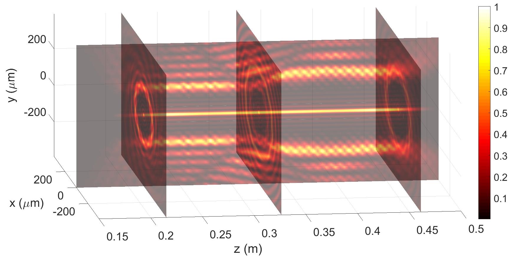
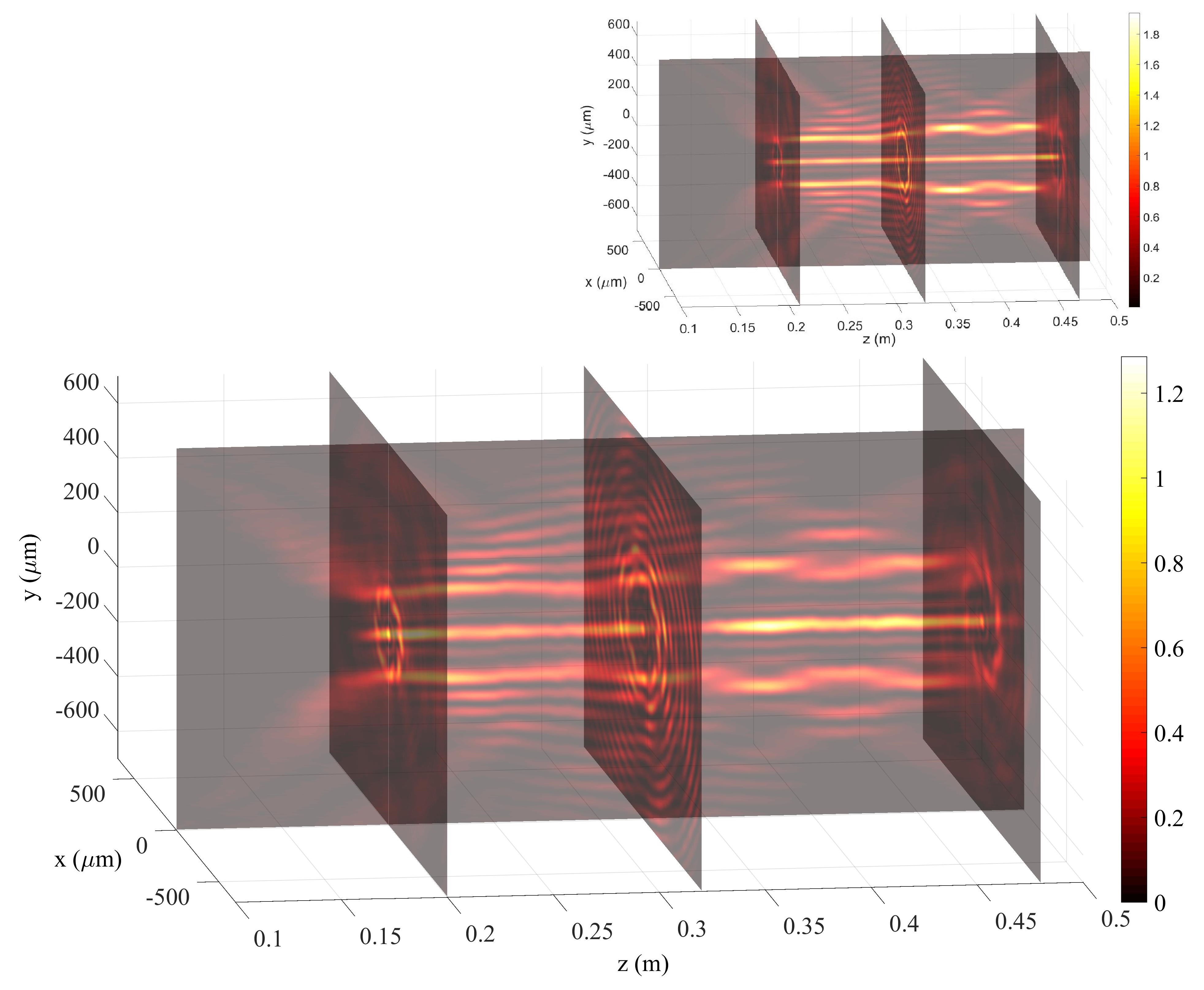
We are going to represent with enough details our first example of a “Lego-beam”: Namely, of a beam whose spatial structure consists of two adjacent cylindrical surfaces, cm and cm long, with corresponding radii of m and m subsequently linked each other; besides a coaxial, central light-segment having spot m and length cm.
To get such a beam, we use our “Lego-beam”-type solution, Eq.(1), and consider only three FWs, one of order zero, and two more of the same order 10 (but with different values of their central longitudinal wave numbers). That is, by inserting in Eq.(1) the non-zero functions (FWs) , and , endowed in the interval m with the following longitudinal intensity shapes:
| (7) |
where is the Kronecker delta function and is the Heaviside function. The corresponding are evaluated on the basis of the wished values for the cylindical surface radii and for the light-segment spot, resulting to be:
| (8) |
Then, the coefficients can be easily obtained via Eq.(5); while the longitudinal and transverse wave numbers, and , respectively, are got by Eqs(3,4). In the present example, it was enough to use 25 Bessel beams in each one of the considered FWs: that is, .
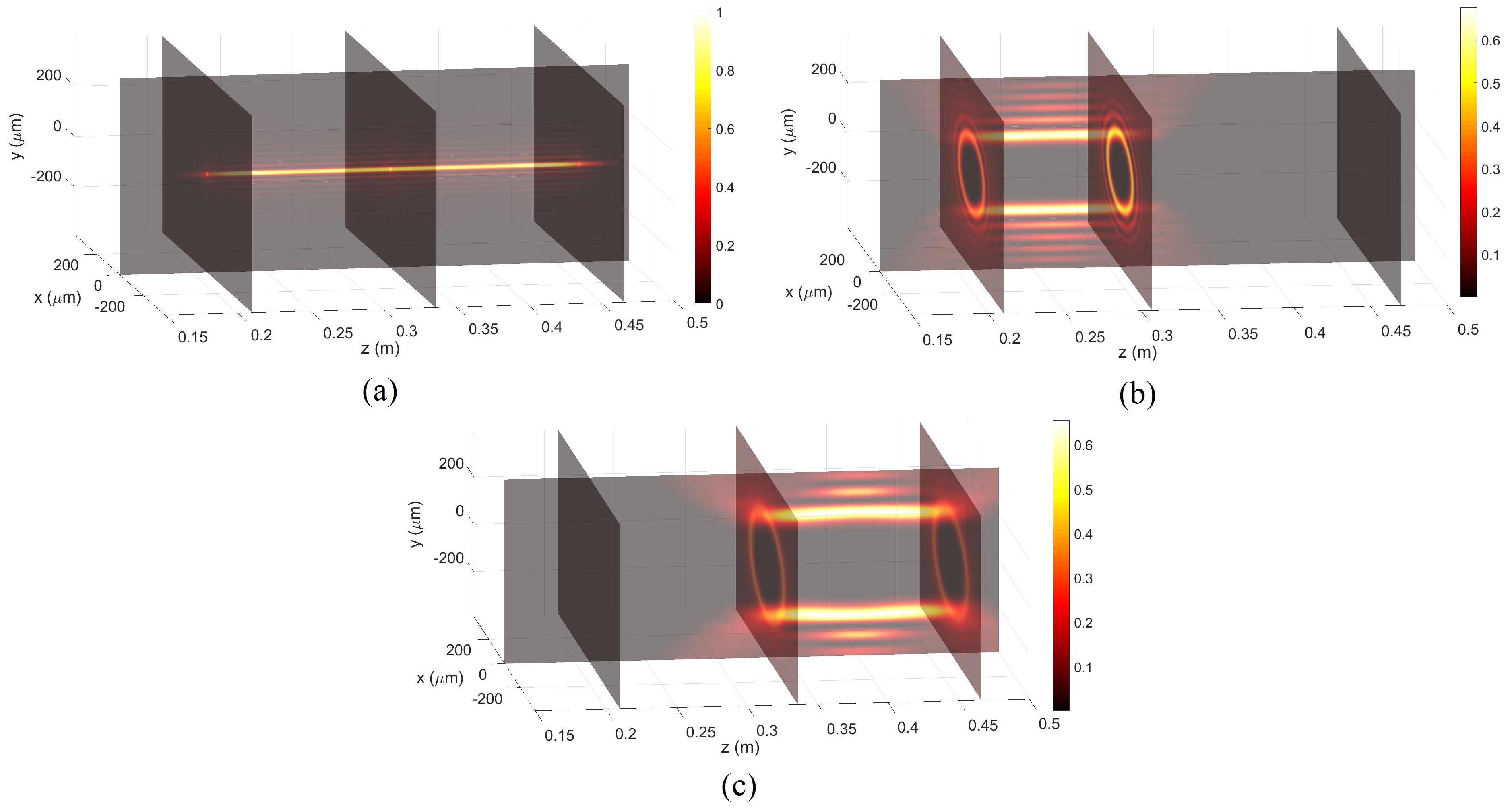
Our result is represented by the following Figures. First, Figures 1(a), 1(b) and 1(c) show, separately, the intensities of the three FWs which are going to compose our beam (in a sense, show the pieces of the “Lego-beam”). Figure 2 shows the intensity, instead, of the resulting beam (that is, of the structured light resulting from the sum of the chosen FWs).
One can notice that the interferences among the three FWs got minimized by the fact that such FWs possess relevant intensities in different space regions.
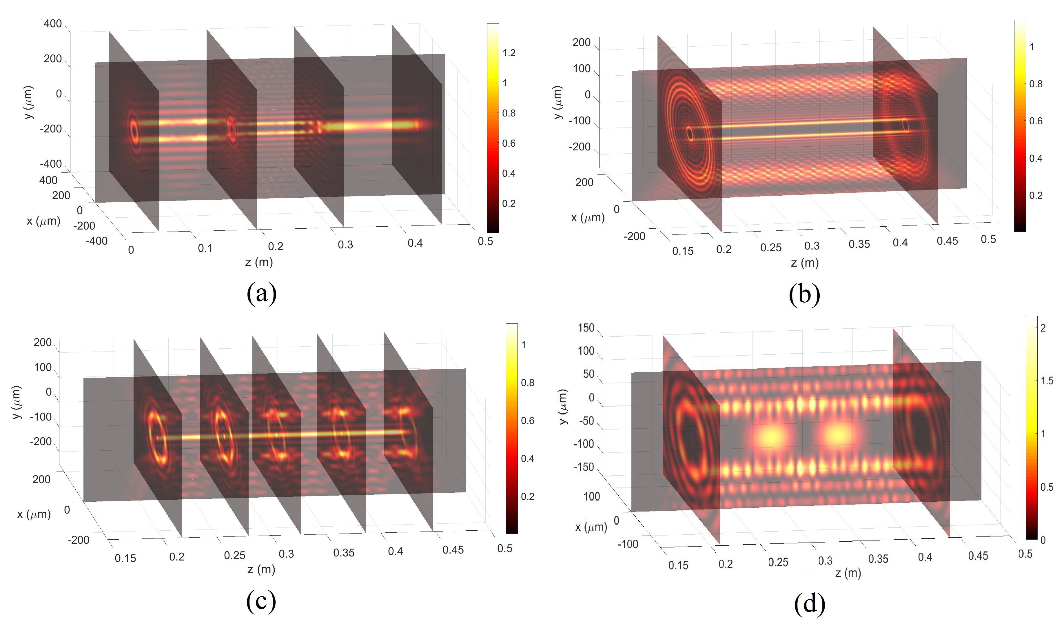
Let us show some further possibilities forwarded by our method, even if –for the sake of conciseness– we skip mathematical details: Namely, let us show in Figs.3 four further light structures obtained from Eq.(1).
The first one, Fig.3(a), depicts the intensity of the “Lego-beam” consisting in two cylindrical surfaces, of different (decreasing) radii, linked one to the other, while the second cylinder on its right side has a light segment acting as a “cork”. Figure 3(b) shows the intensity of a structured light beam formed by two subsequent, coaxial cylindrical surfaces: In this case two FWs with the same order (larger than zero, of course) were adopted. In Fig.3(c) one has a sequence of donut-shaped light structures, with a central coaxial (zero order) light line. At last, Fig.3(d) refers to the intensity of a structured beam, made of a cylindrical surface with two light “embuli” (blockages) inside it.
All these examples refer to cylindrical or threadlike structures (adjacent or coaxial in their location), having transverse sizes of tens of micrometers and longitudinal sizes of tens of centimeters: They being, therefore, highly resistant to diffracting effects.
4 Experimental Confirmations
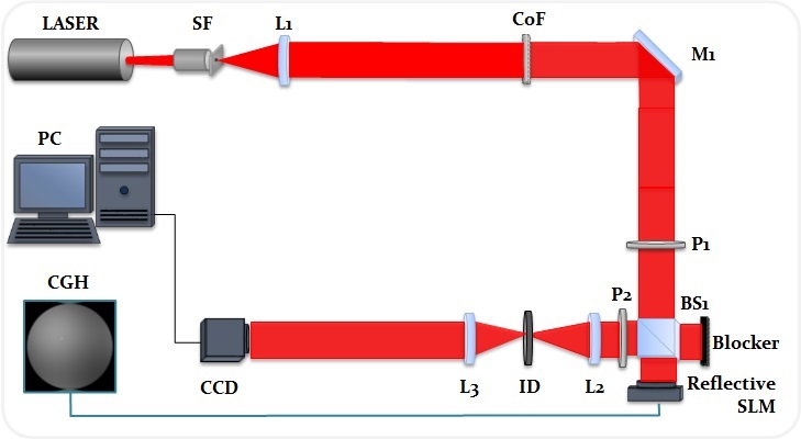
Let us present in this Section a couple of experimental confirmations of our approach, by constructing two “Lego-beams” via a holographic setup that performs the optical reconstruction of computer generated holograms, sent electronically into a reflective Spatial Light Modulator (SLM), used in amplitude modulation mode, followed by a 4F spatial filtering system. Further details can be found in the caption of Fig.4.
We obtain the 2D CGH of a “Lego-beam” through the complex transmittance function (hologram) obtained from the desired resulting beam at the origin , with given by Eq.(1). The hologram equation is expressed by [32, 33, 37, 38] :
| (9) |
where and are amplitude and phase, respectively, of the complex field , quantity being a bias function chosen as a soft envelope for the amplitude . In order to make easier the separation of the different diffraction orders from the encoded complex field , the off-axis reference plane wave is used, shifting, in the Fourier plane, the center of signal information to the spatial frequencies .
The holographic setup used in the experimental reconstruction process of the CGH of our “Lego-beams” is shown in Fig.4. The coherent light from the He-Ne laser (nm) passes through the spacial filter SF and is collimated by lens L1; it is then reflected by mirror M1 and polarized by polarizer P1; when arriving at the beam splitter BS1, the light is directed to the reflective SLM (model LC-R 1080, Holoeye Photonics), where the CGH was sent electronically, and diffracted, proceeding to polarizer P2. To select the correct diffraction order of the reconstructed (diffracted) beam, a 4F filter is used after the SLM, composed of two lenses (L2 and L3) and an iris diaphragm (ID). Finally, the “Lego-beam” is acquired by the CCD camera (model DMK 41BU02.H, Imaging Source), at subsequent locations along .
The first experimentally generated beam possesses its shape similar to that of the first theoretical example, but with different values for the radii of the cylindrical surfaces due to the limited resolution of our SLM. Namely, we generate a beam whose diffraction resistant spatial structure consists in two adjacent cylindrical surfaces, cm and cm long, with the corresponding radii m and m, sequentially linked one to the other; while it coaxially exists a “light segment” having a spot of m and a length of cm.
We use, therefore, our “Lego-beam”-solution, Eq.(1), with three FWs: one zeroth-order FW, and two eighth-order FWs (the latter endowed with different values of their central longitudinal wave numbers). That is, in Eq.(1) the non-zero functions (FWs) are: , and , possessing in the interval m the intensity longitudinal patterns:
| (10) |
where is a Kronecker delta funcion, and an Heaviside function. The corresponding values depend on the chosen cylidrical surface radii and on the light-segment spot, and result to be:
| (11) |
Again, coefficients are evaluated via Eq.(5); while the longitudinal values, , and the transverse ones, , of the wave numbers are given by Eqs(3,4). With regard to the number of terms for each , we adopted , and , respectively.
Figura 5 shows the experimentally generated “Lego-beam”. On its upper right side, in smaller size, we reproduce its theoretical prediction. An excelent agreement is apparent, which confirms validity and applicability of our method.
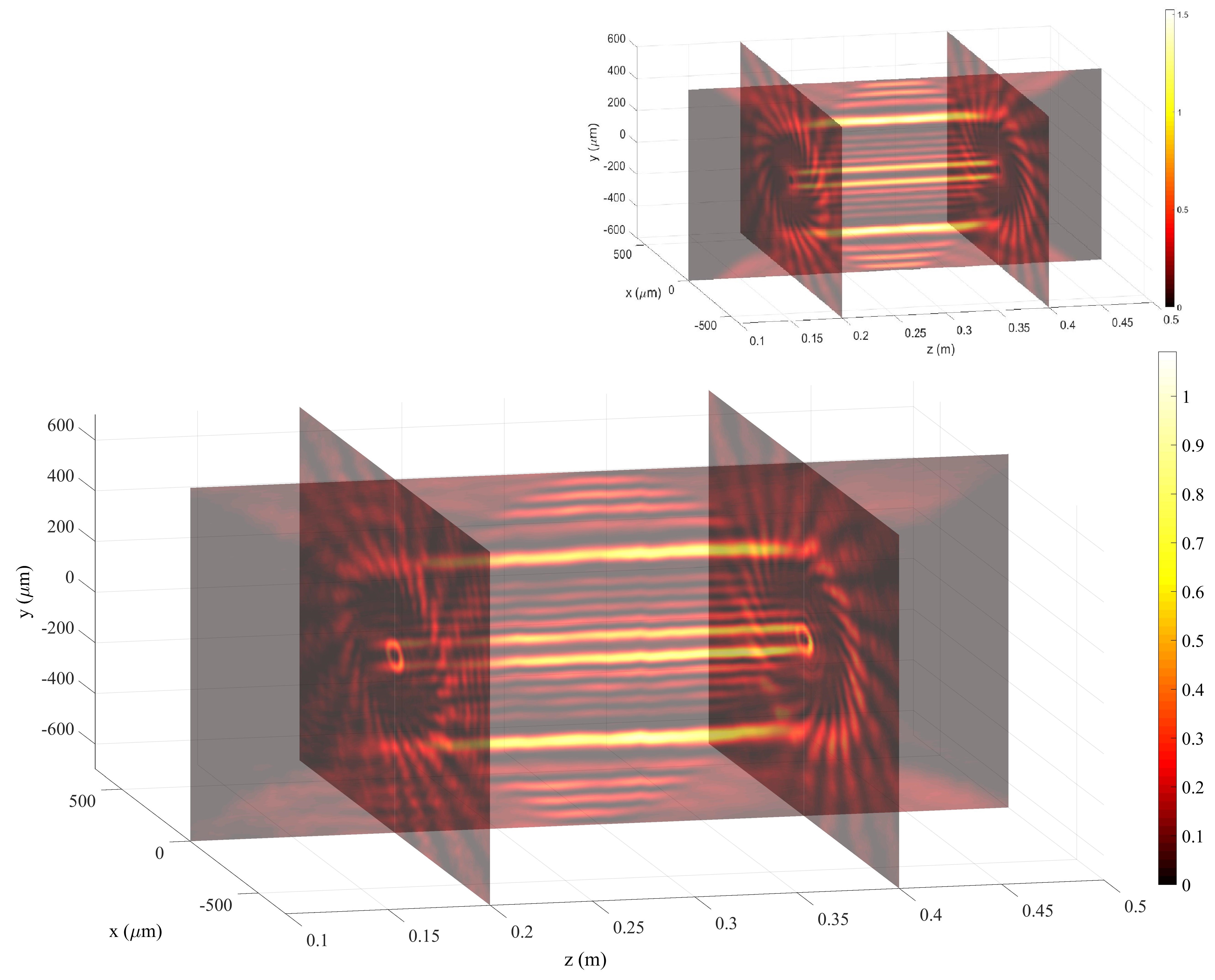
Let us now pass to the second experimentally generated “Lego-beam”. We choose two coaxial cylindric light surfaces, in analogy to our theoretical Fig.3(b), wherein we used two equal-order FWs (while for the experiment we adopt two different-order FWs). More specifically, we want to generate two coaxial light-surfaces, having the same length cm, but the different radii m and m. In other words, let us now adopt the “Lego-beam”-solution, Eq.(1), with two FWs only, the first of order 2, and the second of order 22. Therefore, in Eq.(1) and in the interval m, the non-zero functions (FWs) are and , whose longitudinal intensity patterns are:
| (12) |
where, again, is a Kronecker delta and a Heaviside function. The corresponding values, depending on the chosen cylindrical surface radii, are:
| (13) |
As before, coefficients are evaluated via Eq.(5), and the longitudinal and transverse wave numbers ( and ) are calculated by Eqs(3,4). For this example we use .
Figure 6 shows this second experimentally generated beam, and, on its right side, in smaller size, its theoretical prediction. Once more, an excellent agreement is found between theory and experiment; provided that it is kept in mind our discussion of the interference, between different FWs, present at the end of our Sec. 2.
In connection with this figure, and with Eq.(6), let us add a particular comment: If the external cylinder stays in the region where is positive (negative), in the resulting beam its intensity will be higher (lower) than the internal cylinder’s. Such effects can be avoided, or at least reduced, by properly choosing the (greater or smaller) intensities of the initial cylinders so that in the final beam they result with the same intensity.
5 Conclusions
In this work we present a theoretical method in which “Frozen Wave”-type optical beams (of different orders and/or with different sets of longitudinal wave-number values) are suitably superposed, providing us with really innovative possibilities (called by us “Lego-beams”) in the important field of Structured Light.
Various theoretical examples are developed and, moreover, our method has been experimentally verified by the production of two Lego-beams via a holographic setup, that performs the optical reconstruction of computer generated holograms through a reflective Spatial Light Modulator (SLM) followed by a 4F spatial filtering system.
The study of structured light is known to have played an important role in several areas of optics and photonics; and our present results can find interesting applications in all sectors in which more sophisticated light beams are needed, such as optical tweezers, optical guiding of atoms, light orbital angular momentum control, imaging systems, remote sensing, light detection and ranging, microscopy, metrology, optical communications, quantum information, etc… All these technologies are growing, and mastering the various types of structured light is becoming more and more important [39].
For completeness’ reasons, let us be here a little more specific about the expected applications of our “Lego-beams”, e.g., in the four sectors of optical tweezers for (e.g.) biological manipulations, atoms guiding, non-linear optics, and interaction of electromagnetic radiation with Bose-Einstein condensates:
(i) Optical tweezers are known to be a highly valid instrument for confining and manipulating nano or micro particles, including biological “particles” like bacteria, cells, viruses, etc. The use of Non-Diffracting Beams caused many improvements [8, 9, 10, 11, 12, 13, 14, 15, 16, 17], at the point that it was regarded as revolutionary in a Nature’s paper [13]. Among their advantages, let us mention the possibility of simultaneously imprisoning many scatterers. Ability in the spatial modelling of non-diffracting beams, as by our “Lego-beams”, is certainly useful for optical micro-manipulations, generating new light structures that could not be imagined before: For instance, by linking together a zero-order FW (devoid of orbital angular momentum) with a FW of order 1 or more (carrying orbital angular momentum), it becomes possible to create a confining region, wherein the particles do not receive angular momentum, followed by another confining region in which the particles get angular momentum from the optical field and start rotating.
(ii) Another sector where use of non-diffracting beams resulted useful and promising is the optical guiding of neutral atoms, when Bessel beams of order larger than zero (non-diffracting hollow beams) generate optical potentials with the same shape [18, lemb, 20, 21, 22, 23, 24]. Again, the possibility of obtaining diffraction-resistant beams with various interesting, new spatial configurations (by connecting different FWs together), namely our “Lego-beams”, can lead to unprecedented optical potential configurations for guiding, or holding, neutral atoms.
(iii) Applications in material modification, more specifically on the creation of waveguide structures and microchannels for microfluidics through the process of laser-writing, where a femtosecond laser induces a material modification (e.g. refractive index modification) in the longitudinal direction. Studies [40, 41, 42, 43] have related good results for laser micromachining in glass with Bessel beams, obtaining microchannels with 2 m of diameter and with high aspect ratios (up to 40). “Lego-beams” could be used for laser-writing waveguide structures and microchannels (for microfluidics) with a great variety of forms and, due their diffraction resistant characteristics, with long longitudinal lengths.
(iv) A fourth interesting sector would be that of examining (theoretically, and experimentally) the interaction of our “Lego-beams” with Bose-Einstein condensates. The Gross-Pitaevskii equation –describing a weakly interacting Bose-Einstein condensate, at the limit of zero temperature– is known to possess a mathematical structure similar to the non-linear Schroedinger equation of optics. Such a mathematical equivalence suggests that, while in the non-linear Schroedinger equation the light is the wave propagating in a medium constituted of atoms, on the contrary in the Gross-Pitaevsky equation the atoms play the role of the wave (matter wave) and the light acts as the propagation medium [44]. It is tempting, in this context, to investigate in theory and experiments the effect of “Lego-beams” structures on those condensates.
6 Acknowledgments
This work is supported by FAPESP (grants 2015/26444-8 and 16/19131-6), CNPQ (grants 304718/2016-5 and 313153/2014-0), and by CAPES. E.Recami thanks CAPES for a visiting professor fellowship c/o UNICAMP, and Hugo.E.Hernández-Figueroa for his continuous collaboration and interest.
References
- [1] M.Zamboni-Rached, “Stationary optical wave fields with arbitrary longitudinal shape by superposing equal frequency Bessel beams: Frozen Waves,” Opt. Express (17), 4001–4006 (2004).
- [2] Michel Zamboni-Rached, “Diffraction-Attenuation resistant beams in absorbing media,” Opt. Express 14, 1804-1809 (2006).
- [3] M.Zamboni-Rached, E.Recami, and H.E.Hernández-Figueroa, “Theory of ‘frozen waves’: Modeling the shape of stationary wave fields,” J. Opt. Soc. Am. A (11), 2465-2475 (2005).
- [4] Localized Waves, edited by H.E.Hernández-Figueroa, M.Zamboni-Rached, and E.Recami (J.Wiley; Hoboken, NJ, 2008).
- [5] Non-Diffracting Waves, edited by H.E.Hernández-Figueroa, E.Recami, and M.Zamboni-Rached (J.Wiley; Berlin, 2014).
- [6] Structured Light and Its Applications: An Introduction to Phase-Structured Beams and Nanoscale Optical Forces, edited by David L. Andrews (Academic Press, 2008).
- [7] A. Ashkin, J.M. Dziedzic, J.E. Bjorkholm, and S. Chu, “Observation of a single-beam gradient force optical trap for dielectric particles”, Opt. Lett. 11, 288-290 (1986).
- [8] J. Arlt, V. Gárces-Chávez, W. Sibbett, K. Dholakia, “Optical micromanipulation using a Bessel light beam”, Opt. Commun. 197, 239-245 (2001).
- [9] V. Gárces-Chávez, D. McGloin, H. Melville, W. Sibbett, and K. Dholakia, “Simultaneous micromanipulation in multiple planes using a self-reconstructing light beam”, Nature 419, 145-147 (2002).
- [10] M. P. MacDonald et al., “Creation and manipulation of three-dimensional optically trapped structures”, Science 296, 1101-1103 (2002).
- [11] V. Gárces-Chávez, D. McGloin, M.J. Padgett, W. Dultz, H. Schmitzer, and K. Dholakia, “Observation of the transfer of the local angular momentum density of a multiringed light beam to an optically trapped particle”, Phys. Rev. Lett. 91, 093602 (2003).
- [12] D. McGloin, V. Gárces-Chávez, and K. Dholakia, “Interfering Bessel beams for optical micromanipulation”, Optics Letters 28(8), 657-659 (2003).
- [13] D.G.Grier, “A revolution in optical manipulation,” Nature , 810-816 (2003).
- [14] M.Padgett, and R.Bowman, “Tweezers with a twist,” Nat. Photonics (6), 343-348 (2011).
- [15] L.A.Ambrosio, and M.Zamboni-Rached, “Analytical approach of ordinary frozen waves for optical trapping and micromanipulation,” Appl. Opt. (10), 2584-2593 (2015).
- [16] G.Milne, K.Dholakia, D.McGloin, K.Volke-Sepulveda, and P.Zemánek, “Transverse particle dynamics in a Bessel beam,” Opt. Express 15, 13972-13987 (2007).
- [17] V.Garcés-Chávez, D.McGloin, H.Melville, W.Sibbett, and K.Dholakia, “Simultaneous micromanipulation in multiple planes using a self-reconstructing light beam,” Nature 419, 145-147 (2002).
- [18] J.Yin, Y.Zhu, W.Wang, Y.Wang, and W.Jhe, “Optical potential for atom guidance in a dark hollow laser beam”, J. Opt. Soc. Am. B 15, 25-33 (1998).
- [19] V.E. Lembessis, “A mobile atom in a Laguerre-Gaussian laser beam”, Opt. Commun. 159, 243 (1999).
- [20] J. Arlt, T. Hitomi and K. Dholakia, “Atom guiding along Laguerre-Gaussian and Bessel light beams”, Applied Physics B 71(4), 549-554 (2000).
- [21] D. P. Rhodes, G.P.T. Lancaster, J. Livesey, D. McGloin, J. Arlt, and K. Dholakia, “Guiding a cold atomic beam along a co-propagating and oblique hollow light guide”, Opt. Commun. 214, 247-254 (2002).
- [22] E. Courtade, O. Houde, J.F. Clement, P. Verkerk, and D. Hennequin, “Dark optical lattice of ring traps for cold atoms”, Phys. Rev. A 74, 031403 (2006).
- [23] J.Arlt, T. Hitomi, and K. Dholakia, “Atom guiding along Laguerre-Gaussian and Bessel light beams,” Appl. Phys. B 71, 549-554 (2000).
- [24] E.G.P.Pachon, M.Zamboni-Rached, A.H.Dorrah, M.Mojahedi, M.R.R.Gesualdi, and G.G.Cabrera, “Architecting new diffraction-resistant light structures and their possible applications in atom guidance,” Opt. Express (22), 25403-25408 (2016).
- [25] T.A.Planchon, L.Gao, D.E.Milkie, M.W.Davidson, J.A.Galbraith, C.G.Galbraith, and E.Betzig, “Rapid three-dimensional isotropic imaging of living cells using Bessel beam plane illumination,” Nat. Methods (5), 417-423 (2014).
- [26] A.H.Dorrah, M.Zamboni-Rached, and M.Mojahedi, “Controlling the topological charge of twisted light beams with propagation,” Phys. Rev. A 93, 063864 (2016).
- [27] L. Allen, and M. Padgett, “Equivalent geometric transformations for spin and orbital angular momentum of light”, J. Mod. Opt. 54, 487-491 (2007).
- [28] D.L. Andrews, L.C.D. Romero, and M. Babiker,“ On optical vortex interactions with chiral matter”, Opt. Commun. 237, 133-139 (2004).
- [29] F. Araoka, T. Verbiest, K. Clays, and A. Persoons, “Interactions of twisted light with chiral molecules: An experimental investigation”, Phys. Rev. A 71, ???? (2005).
- [30] V. Chavez, D. McGloin, M.J. Padgett, W. Dultz, H. Schmitzer, and K. Dholakia, “Observation of the transfer of the local angular momentum density of a multiringed light beam to an optically trapped particle”, Phys. Rev. Lett. 91, 4 (2003).
- [31] Paraxial light beams with angular momentum, by Bekshaev A., and Soskin M. (New York: Nova Science Publishers, 2008).
- [32] T.A.Vieira, M.R.R.Gesualdi, and M.Zamboni-Rached, “Frozen waves: experimental generation,” Opt. Lett. (11), 2034-2036 (2012).
- [33] T.A.Vieira, M.R.R.Gesualdi, M.Zamboni-Rached, and E.Recami, “Production of dynamic frozen waves: controlling shape, location (and speed) of diffraction-resistant beams”, Opt. Lett. 40(24) 5834-5837 (2015).
- [34] M.Corato Zanarella, and M.Zamboni-Rached, “Electromagnetic frozen waves with radial, azimuthal, linear, circular, and elliptical polarizations,” Phys. Rev. A , 053802 (2016).
- [35] M.Zamboni-Rached, and M.Mojahedi, “Shaping finite-energy diffraction-and attenuation-resistant beams through Bessel-Gauss beam superposition,” Phys. Rev. A , 043839 (2015).
- [36] A.H.Dorrah, M.Zamboni-Rached, and M.Mojahedi, “Generating attenuation-resistant frozen waves in absorbing fluid,” Opt. Lett. (16), 3702-3705 (2015).
- [37] Victor Arrizón, “Optimum on-axis computer-generated hologram encoded into low-resolution phase-modul ation devices,” Opt. Lett. 28 2521-2523 (2003).
- [38] Victor Arrizón, Guadalupe Méndez, and David Sńchez-de-La-Llave, “Accurate encoding of arbitrary complex fields with amplitude-only liquid crystal spatial light modulators”, Opt. Express 13 7913-7927 (2005).
- [39] H.Rubinsztein-Dunlop, et al., “Roadmap on structured light”, J. Opt. 19, 013001 (2017).
- [40] R. R. Gattass and E. Mazur, “Femtosecond Laser Micromachining in Transparent Materials”, Nat. Photonics 2, 219 (2008).
- [41] J. A. Dharmadhikari, A. K. Dharmadhikari, A. Bhatnagar, A. Mallik, P. Chandrakanta Singh, R. K. Dhaman, K. Chalapathi, and D. Mathur, “Writing low-loss waveguides in borosilicate (BK7) glass with a low-repetition-rate femtosecond laser”, Opt. Commun. 284, 630 (2011).
- [42] V. Zambon, N. McCarthy, and M. Piché, “Fabrication of Photonic Devices Directly Written in Glass Using Ultrafast Bessel Beams”, Proc. SPIE 7099, 70992J (2008).
- [43] M. K. Bhuyan, F. Courvoisier, P.-A. Lacourt, M. Jacquot, L. Furfaro, M. J. Withford, and J. M. Dudley, “High aspect ratio taper-free microchannel fabrication using femtosecond Bessel beams”, Opt. Express 18, 566 (2010).
- [44] Federica Cattani, Arkady Kim, Mietek Lisak and Dan Anderson, “Interactions of Electromagnetic Radiation with Bose-Einstein Condensates: Manipulating Ultra-Cold Atoms with Light”, Int. J. Mod. Phys. B 27(6), 1330003 (2013).