Hidden attractors in aircraft control systems with saturated inputs
Abstract
In the paper, the control problem with limitations on the magnitude and rate of the control action in aircraft control systems, is studied. Existence of hidden limit cycle oscillations in the case of actuator position and rate limitations is demonstrated by the examples of piloted aircraft pilot involved oscillations (PIO) phenomenon and the airfoil flutter suppression system.
pacs:
05.45.Xt, 05.45.GgI Introduction
In the paper, the control problem with limitations on the magnitude and rate of the control action in aircraft control systems, is studied. This problem has long attracted the attention of scientists and developers of flight control systems, is still a challenging one, without losing its relevance at the present time.
It is shown in the literature that in the motion of an aerodynamically stable aircraft a stable limit cycle with a small amplitude and an unstable one with a large amplitude can coexist. If the aircraft is aerodynamically unstable, then one of the two stable limit cycles with a small amplitude can be realized. In addition, there is also an unstable limit cycle, the presence of which makes it necessary to study the stability of an aircraft with an automatic control system “in large”, i.e. when large perturbations (including those from the side of a pilot) are applied to the aircraft, they can lead him beyond the amplitude of the unstable limit cycle.
An influence of non-linearities like a “saturation” in a pilot–aircraft loop is commonly treated as a possible origin of the so-called Pilot Involved Oscillation (PIO), which leads to serious degrade of the piloted aircraft performance, up to the stability loss and the aircraft destruction, cf. Dornheim92 ; Shifrin93 . This phenomenon is characterized by rapidly developing oscillations with increasing amplitude at angular velocities, overloads and angular movements of the manned vehicle. The main non-linear factor leading to this phenomenon is, as a rule, the limitation of the speed of deviation of the aircraft control elements (aerodynamic control surfaces of the aircraft), which can lead to a delay in the response of the aircraft to the pilot’s commands. The study of transient regimes with such a motion leads to the need to develop a mathematical theory of global analysis of control systems of aircraft.
As the results obtained, for studying the processes that can arise in nonlinear control systems of aircraft (including nonlinear oscillations), simple computer modeling is an unreliable tool that can lead to wrong conclusions.
The remainder part of the paper is organized as follows. The analytical-numerical method for hidden oscillations localization is briefly recalled in Sec. II. The adopted dynamic actuator model with saturations in the magnitude and rate is given in Sec. III. In Sec. III hidden oscillations in the pilot-aircraft loop (related to the PIO phenomenon) are studied and localized by means of the iterative analytical-numerical method. Hidden oscillations in the unstable aircraft angle-of-attack control system with saturated actuator are demonstrated in Sec. IV. Section V is devoted to hidden oscillations in the pilot-aircraft loop. Hidden limit cycle oscillations in the airfoil flutter feedback suppression system are studied in Sec. VI. Concluding remarks and the future work intentions are given in Sec. VII. Some background information is given in Appendix Appendix. Aeroelastic model parameters.
II Analytical and numerical analysis of oscillations in nonlinear control systems
Further we consider a nonlinear control system with one scalar non-linearity in the Lur’e form
| (1) |
where is a constant -matrix, are constant -dimensional vectors, T denotes transpose operation, is a continuous piecewise-differentiable scalar function, .
One of the main tasks of the investigation of nonlinear dynamical models (1) is the study of established (limiting) behavior of the system after the transient processes are over, i.e., the problem of localization and analysis of attractors (limited sets of system’s states, which are reached by the system from close initial data after transient processes). For numerical localization of an attractor one needs to choose an initial point in the basin of attraction and observe how the trajectory, starting from this initial point, after a transient process visualizes the attractor. Thus, from a computational point of view, it is natural to consider the following classification of attractors being either self-excited either hidden based on the simplicity of finding the basins of attraction in the phase space LeonovK-2013-IJBC ; KuznetsovL-2014-IFACWC ; LeonovKM-2015-EPJST ; Kuznetsov-2016 : self-excited attractor has the basins of attraction touching an unstable stationary point, thus, can be revealed numerically by the integration of trajectories111 Remark that in numerical computation of trajectory over a finite-time interval it may be difficult to distinguish a sustained oscillation from a transient oscillation (a transient oscillating set in the phase space, which can nevertheless persist for a long time). , started in small neighborhoods of the unstable equilibrium, while hidden attractor has the basin of attraction, which does not touch equilibria, and is hidden somewhere in the phase space LeonovK-2013-IJBC ; KuznetsovL-2014-IFACWC ; LeonovKM-2015-EPJST ; Kuznetsov-2016 . For example, hidden attractors in systems (1) correspond to the case of multistability when the stationary point is stable and coexist with a stable periodic orbit, or there are several coexisting periodic orbits. The classification of attractors as being hidden or self-excited was introduced by in connection with the discovery of the first hidden Chua attractor KuznetsovLV-2010-IFAC ; LeonovKV-2011-PLA ; BraginVKL-2011 ; LeonovKV-2012-PhysD ; KuznetsovKLV-2013 ; KiselevaKKKLYY-2017 ; StankevichKLC-2017 and has captured much attention (see, e.g. BurkinK-2014-HA ; LiSprott-2014-HA ; LiZY-2014-HA ; PhamRFF-2014-HA ; ChenLYBXW-2015-HA ; KuznetsovKMS-2015-HA ; SahaSRC-2015-HA ; SemenovKASVA-2015 ; SharmaSPKL-2015-EPJST ; ZhusubaliyevMCM-2015-HA ; WeiYZY-2015-HA ; DancaKC-2016 ; JafariPGMK-2016-HA ; MenacerLC-2016-HA ; OjoniyiA-2016-HA ; PhamVJVK-2016-HA ; RochaM-2016-HA ; WeiPKW-2016-HA ; Zelinka-2016-HA ; BorahR-2017-HA ; BrzeskiWKKP-2017 ; FengP-2017-HA ; JiangLWZ-2016-HA ; KuznetsovLYY-2017-CNSNS ; MaWJZH-2017 ; MessiasR-2017-HA ; SinghR-2017-HA ; VolosPZMV-2017-HA ; WeiMSAZ-2017-HA ; ZhangWWM-2017-HA ).
II.1 Analysis of oscillations by the harmonic balance and describing function method
The describing function method (DFM) is a widely used engineering method for the search of oscillations which are close to the harmonic periodic oscillations. This method is not strictly mathematically justified and is one of the approximate methods of analysis of oscillations (see, e.g. KrylovB-1947 ; PopovPaltov63 ; Khalil-2002 ; LiuDowellThomas_JFS05 ).
Let us recall a classical way of applying the DFM. Introduce a transfer function , where is a complex variable, is a unit matrix. In order to find a periodic oscillation, a certain coefficient of harmonic linearization is introduced in such a way that the matrix has a pair of pure-imaginary eigenvalues . The numbers and are defined by
| (2) |
If such and exist, then system (1) has a periodic solution for which Consider , then, following the DFM, the amplitude of oscillation can be obtained from the equation
| (3) |
where is called a describing function. Assume that , then one can use the following initial data
| (4) |
for numerical localization of an attractor. However it is known that classical DMF can suggest the existence of non-existing periodic oscillation (see, e.g. Shahgildyan-1972 ; KudryashovaKLYY-2017 ) and initial data (4) does not necessarily lead to the localization of an attractor.
To get initial data in the basin of attraction of an attractor, we can use the following modification of the DFM LeonovK-2013-IJBC . Let us change by , where is a small parameter, and consider the existence of a periodic solution for system
| (5) |
Consider a linear non-singular transformation222Such transformation exists for non-degenerate transfer functions , such that system (5) is transformed to the form
| (6) | ||||
where , are scalars, , and are -dimensional vectors, and are scalars; is a constant matrix all eigenvalues of which have negative real parts.
Theorem 1
(LeonovK-2013-IJBC ) If there exists a number such that
| (7) |
then system (5) has a stable periodic solution with initial data
| (8) |
Remark that there are known examples where DFM cannot reveal the existing oscillation (see, e.g. Tzipkin-1984 ; BraginVKL-2011 ; LeonovK-2013-IJBC ). For example, well-known Aizerman’s and Kalman’s conjectures on the absolute stability of nonlinear control systems are valid from the standpoint of DFM, while there are known various counterexamples of nonlinear systems where the only equilibrium, which is stable, coexists with a hidden periodic oscillation (see, e.g. Pliss-1958 ; Fitts-1966 ; Barabanov-1988 ; BernatL-1996 ; LeonovBK-2010-DAN ; BraginVKL-2011 ; LeonovK-2011-DAN ; LeonovK-2013-IJBC ; the corresponding discrete examples are considered in Alli-Oke-2012-cu ; HeathCS-2015 ). In this case the DFM can be justified and analog of Theorem 1 can be obtained for a special class of nonlinearities only LeonovK-2013-IJBC . For example Fitts-1966 ; LeonovK-2013-IJBC ; LeonovM-2017-DAN , system with transfer function
has infinite sector of linear stability, but, e.g., for nonlinearity a hidden attractor can be found numerically.
II.2 Localization of hidden oscillations by the continuation method and describing function methods
Consider an analytical-numerical procedure for the hidden attractors localization based on the continuation method and DFM. For that we construct a finite sequence of functions
such that system (1) with initial function has a nontrivial attractor , which either is self-excited and can be visualized by the initial data from small vicinity of one of the equilibria either can be visualized by the initial data (8). On each next step of the procedure (i.e. for ), the initial point for a trajectory to be integrated is chosen as the last point of the trajectory integrated on the previous step. Following this procedure and sequentially increasing , two alternatives are possible: the points of are in the basin of attraction of attractor , or while passing from system (1) with the function to system (1) with the function , a loss of stability bifurcation is observed and attractor vanishes. If, while changing from to , there is no loss of stability bifurcation of the considered attractors, then an attractor for the original system with (at the end of the procedure) is localized.
III Modeling dynamical actuator with saturations
In the linear settings, an aircraft actuator is usually modeled by the second-order differential equation as
| (9) |
or, in the Laplace transform representation, as
| (10) |
where denotes the commanded controlling surface (elevator) deflection, stands for the actual deflection, are the actuator natural frequency and damping ratio, respectively, denotes the Laplace transform variable.
In the present study, more realistic actuator model involving both magnitude and rate limitations is considered instead of the linear one (9). Following BiannicTarbouriech_06 ; BiannicTarbouriech09 , let us replace (9) by the nonlinear model shown in Fig. 1. This nonlinear model involves two limited integrators which are dynamic nonlinearities. Integrator 1 is associated to the rate limitation , while Integrator 2 corresponds to the magnitude limitation .
The limited nonlinear dynamic integrator with input , output and the saturation level (i.e. for all ; we assume that the limitations are symmetrical) is described by the following model:
| (11) |
where denotes the logical “AND” operation.
In the Lur’e form, nonlinear integrator (11) may be approximately described by the following model BiannicTarbouriech_06 ; BiannicTarbouriech09 :
| (12) |
where gain is sufficiently large. More precisely, as follows from [Lemma 5.1]BiannicTarbouriech09 for any continuous input signal with bounded derivatives, the approximation error tends to zero when the tuning parameter increases.

IV Unstable aircraft angle-of-attack control system with saturated actuator
Consider the following linearized model of short-term dynamics of an unstable aircraft in the vertical plane as in BiannicTarbouriech09 :
| (14) |
where , and denote the angle-of-attack, the pitch-rate and the elevator deflection, respectively; , , , , are the aircraft model parameters which are assumed to be constant during the considered time slot. Let the following proportional feedback law be realized by means of the aircraft longitudinal stability augmentor:
| (15) |
where , are stability augmentor gains, is the control wheel deflection, produced by a pilot. In the sequel, model (14) parameters are taken as follows (see BiannicTarbouriech09 ): , , , , (in SI units). Note that and, therefore, the considered aircraft model is weathercock unstable with respect to the angle of attack. Parameter of stability augmentor (15) is taken as .
In the present example, the actuator dynamics are described by (13) taking into account limiting the maximum speed of moving the aircraft controlling surface. Such a limitation may appear due to the saturation of the of hydraulic fluid supply to the cylinder when the supplying channels are fully opened. The actuator position limitation is assumed to be sufficiently large, therefore it is neglected. To simplify the exposition, without loss of generality, gain in (15) is taken equal to one. The actuator model parameters (in SI units) are taken as , , .
IV.1 Localization of hidden oscillations
Let us apply to the considered system the method of hidden oscillations localization, described in Sec. II, cf. Bragin_TiSU11 ; Dudkowski_PR16 ; LeonovKuznetsov_IJBC13 ; LeonovK-2011-IFAC ; LeonovKV-2011-PLA ; LeonovKV-2012-PhysD . To this end represent the system model (13), (14), (15) (assuming ) to the state-space form (1), considering as an input of the linear part of the system, and as its output. Introduce the state-space vector as , . This leads to the following matrices in (1):
| (16) |
The block diagram of the linear part of the system is demonstrated in Fig. 2 (on this diagram, the Simulink State-Space block represents model (14)).

For the given above parameter values (, , , , , , , , ) one gets
| (17) |
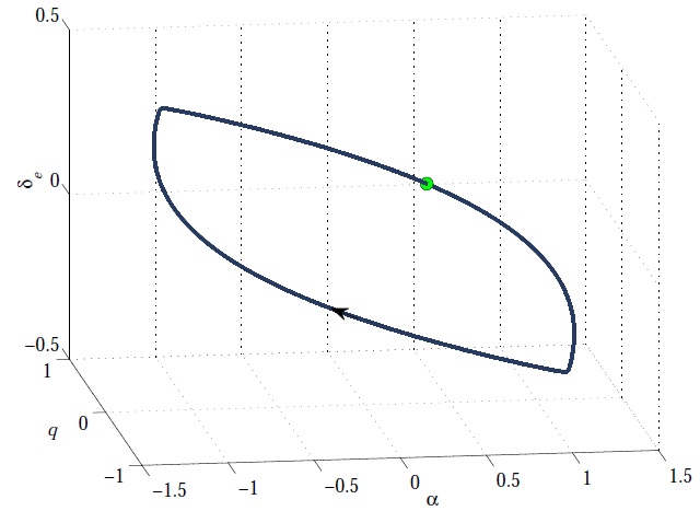
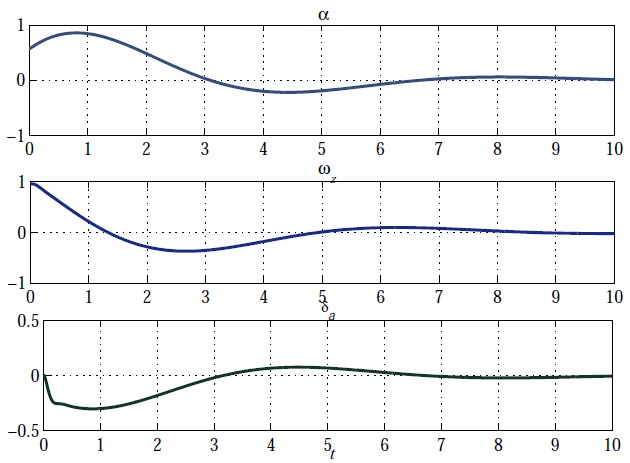
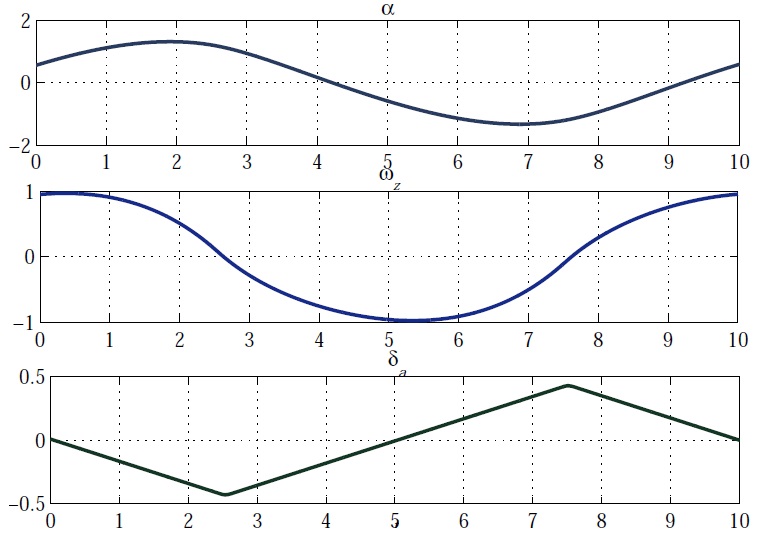
Application the iterative procedure of Sec. II shows existence in the system the limit cycle oscillation with the initial point . Projection of the limit cycle to the subspace is depicted in Fig. 3. Time histories of variables , , for given are plotted in Figs. 4, 5. Figure 4 represents the case when no rate limitations are taken into account (i.e. the case of a linear actuator model (9)), while Fig. 5 refers to the case of nonlinear actuator model (13) and reflects an influence of the rate limitations to the overall system behavior.
V Aircraft-pilot loop
The problem of control with limitations on the magnitude, rate, and energy of the control action due to its relevance for practice has attracted the attention of scientists and developers of automatic control systems for aircrafts for a long time, see AndrievskyKL-2017 ; BriegerKerr_ACC07 ; BriegerKerr_ACC08 ; AviationSafety97 ; QueinnecTarbouriech_IC06 ; TarbouriechTurner09 and the references therein.
Influence of non-linearities like the “saturation” can also cause the so-called Pilot Involved Oscillations (PIOs), which violate the aircraft piloting, cf. Powers84 ; AviationSafety97 ; PachterMiller_CS98 ; BriegerKerr_ACC07 ; BriegerKerr_ACC08 ; BriegerKerrPostlethwaite_JCD12 ; BriegerKerr_JGCD12 ; AndrievskyKLP-2013-IFAC ; AcostaYildiz14 ; AndrievskyKL-2015 ; AndrievskyKL-2017 . This phenomenon is characterized by rapidly developing fluctuations with increasing amplitude of angular velocities, accelerations, and angular movements of manned aircraft. Despite the nature of PIO is not completely clear, it is generally recognized that the main factor leading to PIO is limitations of the rate of deviation of the aircraft control inputs (such as the controlling aerodynamic surfaces). This restriction may result in a delay in the response of the aircraft to the pilot commands.
As noted in AviationSafety97 ; Duda_ASTE98 , PIOs usually arise in situations where the pilot is trying to maneuver by aircraft with a high precision. The study of transient regimes with this motion leads to the need of development a mathematical theory of global analysis of flight control systems.
Below the hidden PIO-like oscillations in aircraft-pilot contour are studied based by the example of piloted research aircraft X-15. The transfer function of X-15 research aircraft longitudinal dynamics from the elevator deflection to pitch angle is taken as follows AlcalGordillo_ACC04 ; AmatoIervolino_ECC01 ; AmatoIervolino_CDC00 ; AndrievskyKL-2017 ; MehraPrasanth_CCA98 :
where denotes the elevator deflection with respect to the trimmed value, stands for the pitch angle (all variables are given in the SI units), .
The pilot is usually modeled as a serial element in the closed-loop system. Having enough flight skills, the pilot develops a stable relationship between his control action and a specific set of flight sensor signals McRuer67 . Based on BarbuReginatto_ACC99 ; LoneCooke_AEST14 ; McRuer67 the following pilot model in the form of a lead-lag-delay unit is taken in the present study:
| (18) |
where is the displayed error between desired pitch angle and actual one ; denotes the pilot’s control action, applied to the elevator servo; is the pilot static gain; is the lead time constant; stands for the lag time constant; denotes the effective time delay, including transport delays and high frequency neuromuscular lags. Since the present paper is focused to studying autonomous systems behavior, it is assumed in the sequel that and, therefore, .
To apply the method of LeonovKV-2012-PhysD ; Bragin_TiSU11 ; LeonovKuznetsovYuldahsev_DM11 ; LeonovKuznetsov_IJBC13 , the time-delay transfer function in pilot model (18) is approximated employing the first-order Pade representation GolubLoan89 as . This leads to the following second-order model of the pilot dynamics:
| (19) |
Finally, the transfer function of the open-loop aircraft-pilot system from elevator deflection to the pilot’s control action has the following form:
| (20) |
In the present study the pilot model parameters are taken as: , s, s, s. Consequently, one obtains the following transfer function :
| (21) |
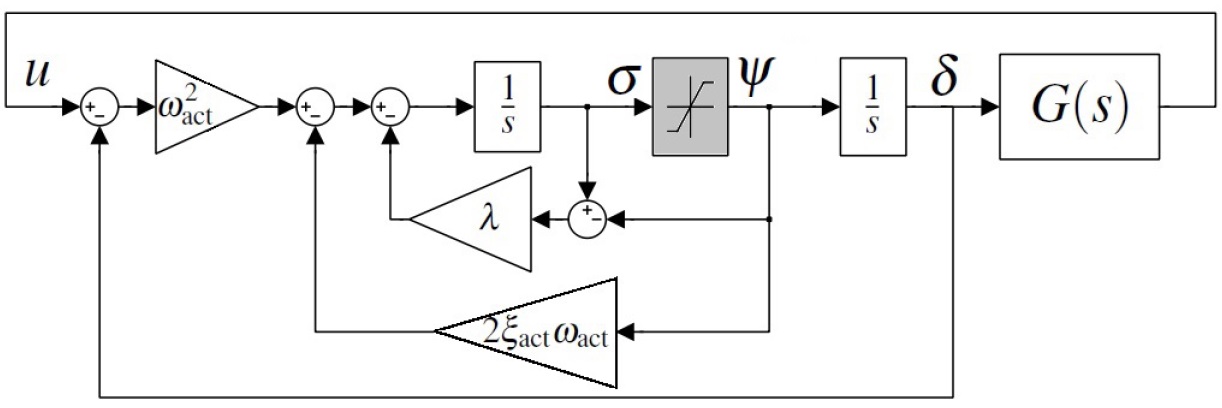
The actuator is modeled as a second-order dynamical unit with a rate limitation (13). The actuator model parameters are taken as rad/s, , rad/s, s-1. Block-diagram of the closed-loop aircraft-pilot system (13), (21) with saturated actuator model is pictured in Fig. 6.
V.1 Localization of hidden oscillations
Let us apply the procedure of hidden oscillations localization to piloted aircraft control system (13), (21). To this end consider the linear subsystem with input and output (see. Fig. 6) and, following Sec. II, represent it in the state-space form (1). In the considered case, and in a certain basis of state space variables, for given above numerical values of the model parameters, one obtains the following matrices in (1):
| (22) |
If the equilibria of system (1) are stable, for the numerical search of hidden oscillations we can use the continuation method of Sec. II.
Several consequent steps of hidden oscillations localization via the above procedure are illustrated by Fig. 7, where phase trajectory projections to subspace , where denotes the pitch rate, for various values of are depicted. Initial value of is taken as .
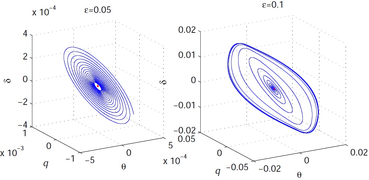
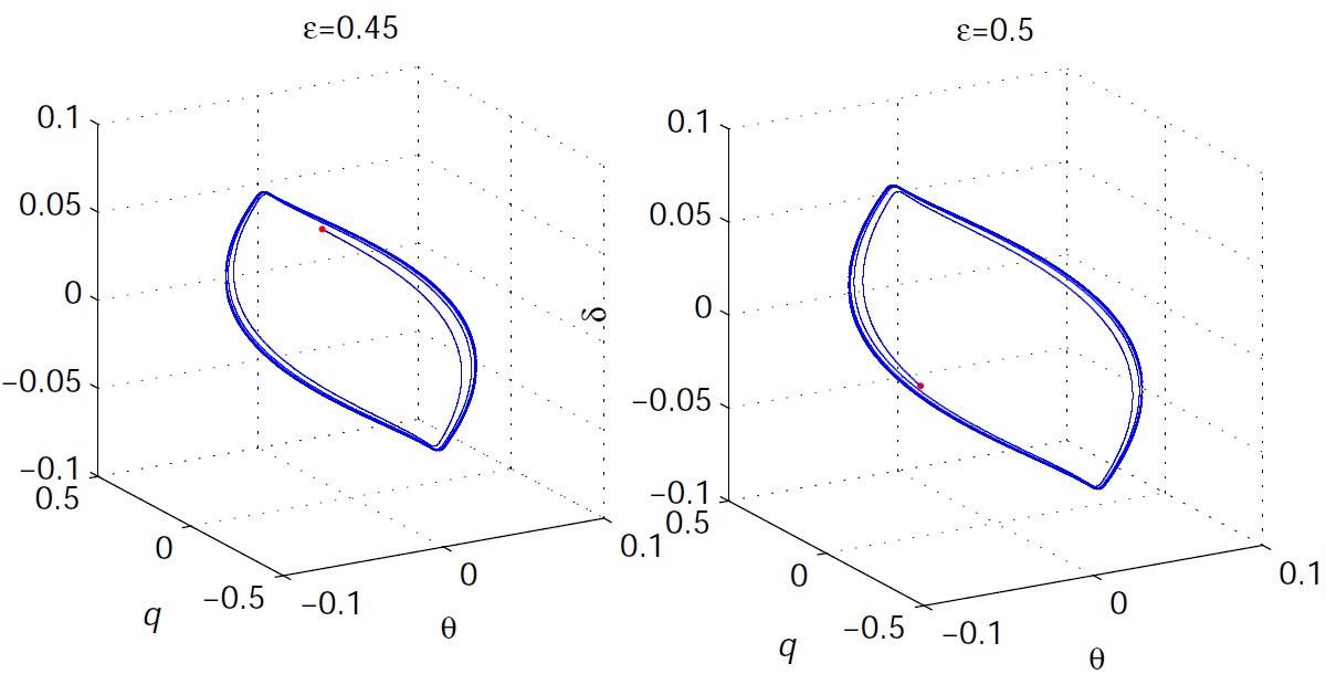
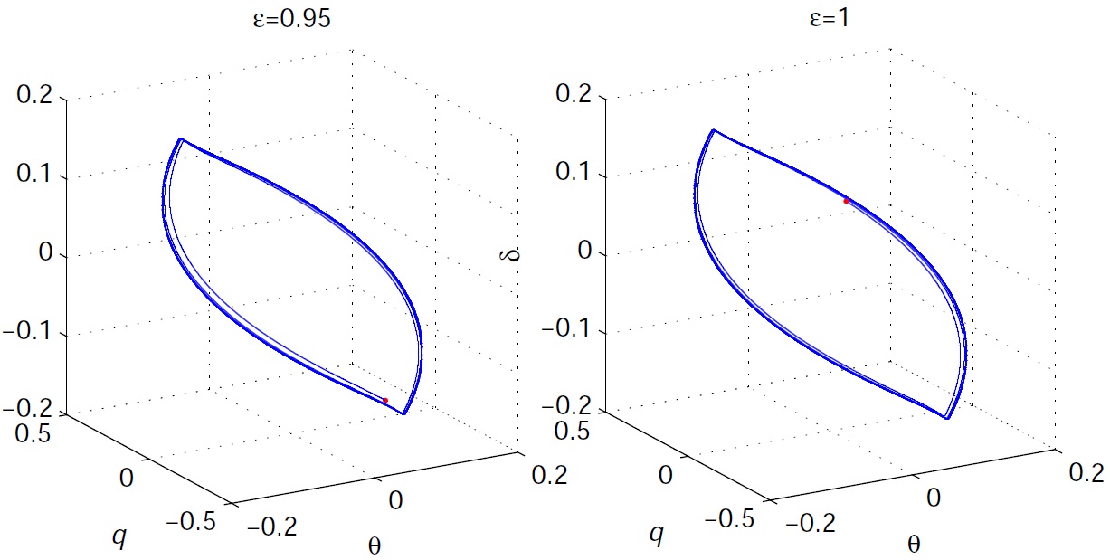
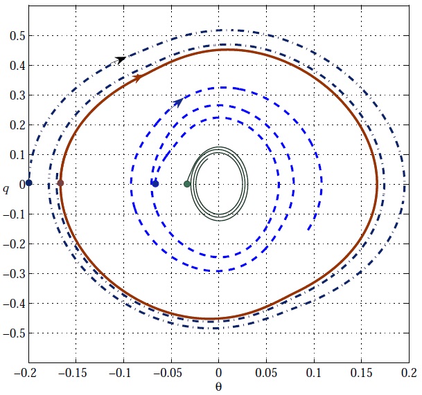
Finally, the following point which belongs to the limit cycle has been found after ten iterations. The simulation results in the form of phase trajectory projections to subspace for various initial conditions are plotted in Fig. 8. Thick solid line on the plot corresponds to the limit cycle oscillation. It is seen that the limit cycle is asymptotically orbitally stable, attracting the neighboring trajectories. The zero equilibrium is asymptotically stable (thin solid line in Fig. 8). The simulations demonstrate that the unstable limit cycle for “intermediate” initial conditions, separating attractivity to the stable limit cycle oscillations and the equilibrium state may also exist.
VI Airfoil flutter suppression
VI.1 Aeroelastic model of an airfoil section
An aeroelastic system describes wing dynamics in the presence of a flow field. Interacting forces between the structure, the moment of inertia and air flow destabilize aircraft by producing flutter and limit cycle oscillation TheodorsenGarrick_TR-685 ; Theodorsen_NACA35 ; Bisplinghoff96 . In the presence of a flow field, the wing at a flight speed oscillates along the plunge displacement direction and rotates at the pitch angle about the elastic axis. Because flutter can eventually damage a wing structure, flutter must be shed during a flight.
Let us use the following steady-state model of the airfoil section flutter dynamics AbdelkefiVasconcellos_ND13 ; Chen_CNSNS12 :
| (23) | |||
| (24) | |||
| (25) |
where denote the plunge displacement; stands for the pitch angle; and are angles of the leading and trailing edges, respectively. The wing structure includes a linear spring oriented along the plunge displacement direction, a rotational spring along the pitch angle, and corresponding dampers. denotes is the total weight of the main wing and supporter, is the weight of the main wing, is the dimensionless distance between the center of mass and the elastic axis, is the moment of inertia, is the midchord, and are the damping coefficients of the pitch angle and the plunge displacement respectively, and are the spring stiffness coefficients of the plunge displacement and the pitch angle respectively, and is a nonlinear term. The nonlinearity of the spring, a hard spring in fact, which is actually a hard spring, is defined as
The aerodynamics force and torque in the low-frequency area and subsonic flight may be represented as follows Theodorsen_NACA35 ; TheodorsenGarrick_TR-685 ; Chen_CNSNS12 :
| (26) | |||
| (27) |
where is air density, is the flight speed, is the dimensionless distance between the elastic axis and the mid-chord; is the windspan length, , are the lift coefficient and moment coefficient per unit angle of attack respectively; , are the lift coefficient and moment coefficient per unit angle respectively against the trailing edge, respectively; , are the lift coefficient and moment coefficient per unit angle, respectively, against the leading edge; , , are the moment derivative coefficient per unit angle of attack, trailing edge and leading edge, respectively. According to Chen_CNSNS12 , they are defined as
| (31) |
Denote the state-space vector as ; . Then
| (37) |
where , , , , , , , , , , , , , are model parameters which are assumed to be constant on the considered time interval.
Let us linearize (37) in the vicinity of the origin and represent it in the vector-matrix form as , where is system matrix, is input matrix, denotes the control action (the controlling surface deflection). Let the airfoil model (37) parameters be taken as in Chen_CNSNS12 , see Appendix Appendix. Aeroelastic model parameters. Matrix eigenvalues are as which shows that system (37) origin is unstable in the Lyapunov sense. Meanwhile, as shown in the series of papers, cf. PriceAlighanbari_JFS95 ; ONeilStrganac_JoA98 ; Ding_AST06 ; LeeLeblanc86 ; ZhangWen_AMC13 ; PriceLee_JA95 ; AlighanbariPrice_ND96 ; KoStrganacKurdila_ND99 ; Highly_Accurate_Cycle ; ADA384971 ; KoStrganacJunkins_JVC02 ; LiGuo_JSV10 ; Chen_CNSNS12 ; AbdelkefiVasconcellos_ND13 ; BichiouHajjNayfeh_ND16 ; IraniSazesh_ND16 ; HeYang_ND17 ; TianYangGu_ND17 ; WeiMottershead_ASTE17 ; FazelzadehAzadi_JVC17 , due to presence of the cubic nonlinearity in the system model, the system trajectories are bounded and the limit cycle oscillations (the airfoil flutter phenomenon) arise. An illustration of the limit cycle oscillations birth for small initial conditions is given by Fig. 10, where projection of the free motion phase trajectory to subspace for deg, is plotted.

VI.2 Airfoil flutter suppression system
Consider the problem of flutter suppression by controlling the airfoil trailing edge (i.e. assume hereafter that ).
There is a plenty of papers devoted to airfoil flutter active suppression systems, see edwards1977unsteady ; StrganacKo_AIAA99 ; KoStrganacKurdila_ND99 ; KoStrganacJunkins_JVC02 ; LiGuo_JSV10 ; Chen_CNSNS12 ; Piovanelli_ECC16 ; BichiouHajjNayfeh_ND16 ; WeiMottershead_ASTE17 ; FazelzadehAzadi_JVC17 for mentioning a few. To simplify the exposition by avoiding unnecessary difficulties in control law synthesis, in the present study the widespread LQR-control design technique is employed.
Consider the static state feedback control law , where state-space vector , as in (37), is a measured plant state, is matrix (row vector) of the controller parameters. Introduce the linear-quadratic performance index with a given positively defined matrix and a non-negative scalar . Employing the standard MATLAB routine lqr one obtains the state feedback vector , minimizing performance index .
Let us pick up , . MATLAB linear-quadratic optimization routine lqr leads then to the following state feedback vector . This gives the closed-loop linearized system matrix with the eigenvalues , ensuring asymptotic convergent system behavior in the close vicinity of the origin. Time histories of , for controlled motion for the case of the “ideal” static state feedback controller at the initial point deg, are depicted in Fig. 11. The case of dynamical actuator with the magnitude and rate limitations is considered below.

Since we focus our attention to existence of hidden oscillation rather than to controller design problems, for simplicity, in the above control law synthesis, the actuator dynamics have been omitted and the assumption that was adopted. Let us check the control system performance taking into account the actuator model. To this end a second-order actuator model with the output magnitude and rate saturations (12), described in Sec. III is used where , , are substituted by , , respectively. In the present study is taken that deg, grad/s. , rad/s. Gain in (12) is set to .


VI.3 Localization of hidden oscillation
The numerical evaluation shows that in the linear approximation, the actuator dynamics do not effect significantly the closed-loop system performance, as is seen from the plots of Fig. 12. In this figure, time histories of variables , for various (the other initial state variables are set to zero), normalized with respect to their maximal values are plotted. Comparing the curves depicted on Fig. 11 with the corresponding (solid) curves of Fig. 12, one may notice that in the linear consideration of actuator dynamics (when the saturations are not active), the unmodelled actuator dynamics (9) do not lead to significant degradation of the overall system performance. The case of deg may be treated as a “boundary” one, when the nonlinearities become active. If the initial conditions are sufficiently large, the feedback controller looses its stabilizing properties and the limit cycle oscillation appears. This oscillation can not be found by linearization of the system model in the vicinity of the origin and, therefore, may be referred to as a “hidden” one. This phenomenon is illustrated by Fig. 13, where the system trajectories in the subspace for deg and deg are plotted. In the first case they tend to the origin, in the second one the limit circle oscillation occurs. By applying the hidden oscillations localization procedure of Sec. II, the initial point of limit cycle oscillation is found as rad, rad/s, m, m/s, rad, rad/s. The projection of the limit cycle phase plot to the subspace is plotted in Fig. 14.
VII Conclusions
In the paper, the control problem with limitations on the magnitude and rate of the control action in aircraft control systems, is studied. Existence of hidden limit cycle oscillations in the case of actuator position and rate limitations is demonstrated by the examples of piloted aircraft PIO phenomenon and the airfoil flutter suppression system. Hidden oscillations in the pilot-aircraft loop are studied and localized by means of the iterative analytical-numerical method.
Acknowledgments
This work was supported by Russian Science Foundation project (14-21-00041).
Appendix. Aeroelastic model parameters
| m | kg m2 | ||
| kg m2/s | |||
| kg/s | N/m | ||
| kg | |||
| kg | |||
| m | |||
| kg/m3 |
Model (37) parameters are defined by the following expressions, see Chen_CNSNS12 :
| (41) |
References
- (1) M. Dornheim, Report pinpoints factors leading to YF-22 crash, Aviation Week and Space Technology 137 (1992) 53–54.
- (2) C. Shifrin, Sweden seeks cause of Gripen crash, Aviation Week and Space Technology 139 (1993) 78–79.
- (3) G. A. Leonov, G. V. Kuznetsov, Hidden attractors in dynamical systems. From hidden oscillations in Hilbert-Kolmogorov, Aizerman, and Kalman problems to hidden chaotic attractors in Chua circuits, Int J. Bifurcation and Chaos 23 (1) (2013) 1–69. doi:10.1142/S0218127413300024.
- (4) N. Kuznetsov, G. Leonov, Hidden attractors in dynamical systems: systems with no equilibria, multistability and coexisting attractors, IFAC Proceedings Volumes 47 (2014) 5445–5454. doi:10.3182/20140824-6-ZA-1003.02501.
- (5) G. Leonov, N. Kuznetsov, T. Mokaev, Homoclinic orbits, and self-excited and hidden attractors in a Lorenz-like system describing convective fluid motion, Eur. Phys. J. Special Topics 224 (8) (2015) 1421–1458. doi:10.1140/epjst/e2015-02470-3.
- (6) N. Kuznetsov, Hidden attractors in fundamental problems and engineering models. A short survey, Lecture Notes in Electrical Engineering 371 (2016) 13–25, (Plenary lecture at International Conference on Advanced Engineering Theory and Applications 2015). doi:10.1007/978-3-319-27247-4\_2.
- (7) N. Kuznetsov, G. Leonov, V. Vagaitsev, Analytical-numerical method for attractor localization of generalized Chua’s system, IFAC Proceedings Volumes 43 (11) (2010) 29–33. doi:10.3182/20100826-3-TR-4016.00009.
- (8) G. A. Leonov, N. V. Kuznetsov, V. I. Vagaitsev, Localization of hidden Chua’s attractors, Physics Letters A 375 (23) (2011) 2230–2233. doi:10.1016/j.physleta.2011.04.037.
- (9) V. Bragin, V. Vagaitsev, N. Kuznetsov, G. Leonov, Algorithms for finding hidden oscillations in nonlinear systems. The Aizerman and Kalman conjectures and Chua’s circuits, Journal of Computer and Systems Sciences International 50 (4) (2011) 511–543. doi:10.1134/S106423071104006X.
- (10) G. A. Leonov, N. V. Kuznetsov, V. I. Vagaitsev, Hidden attractor in smooth Chua systems, Physica D 241 (18) (2012) 1482–1486. doi:10.1016/j.physd.2012.05.016.
- (11) N. Kuznetsov, O. Kuznetsova, G. Leonov, V. Vagaitsev, Analytical-numerical localization of hidden attractor in electrical Chua’s circuit, Lecture Notes in Electrical Engineering 174 (4) (2013) 149–158. doi:10.1007/978-3-642-31353-0\_11.
- (12) M. Kiseleva, E. Kudryashova, N. Kuznetsov, O. Kuznetsova, G. Leonov, M. Yuldashev, R. Yuldashev, Hidden and self-excited attractors in Chua circuit: synchronization and SPICE simulation, International Journal of Parallel, Emergent and Distributed Systems (2017) 1–11 doi:10.1080/17445760.2017.1334776.
- (13) N. Stankevich, N. Kuznetsov, G. Leonov, L. Chua, Scenario of the birth of hidden attractors in the Chua circuit, International Journal of Bifurcation and Chaos 27 (12), accepted.
- (14) I. Burkin, N. Khien, Analytical-numerical methods of finding hidden oscillations in multidimensional dynamical systems, Differential Equations 50 (13) (2014) 1695–1717.
- (15) C. Li, J. Sprott, Coexisting hidden attractors in a 4-D simplified Lorenz system, International Journal of Bifurcation and Chaos 24 (03), art. num. 1450034.
- (16) Q. Li, H. Zeng, X.-S. Yang, On hidden twin attractors and bifurcation in the Chua’s circuit, Nonlinear Dynamics 77 (1-2) (2014) 255–266.
- (17) V.-T. Pham, F. Rahma, M. Frasca, L. Fortuna, Dynamics and synchronization of a novel hyperchaotic system without equilibrium, International Journal of Bifurcation and Chaos 24 (06), art. num. 1450087.
- (18) M. Chen, M. Li, Q. Yu, B. Bao, Q. Xu, J. Wang, Dynamics of self-excited attractors and hidden attractors in generalized memristor-based Chua’s circuit, Nonlinear Dynamics 81 (2015) 215–226.
- (19) A. Kuznetsov, S. Kuznetsov, E. Mosekilde, N. Stankevich, Co-existing hidden attractors in a radio-physical oscillator system, Journal of Physics A: Mathematical and Theoretical 48 (2015) 125101.
- (20) P. Saha, D. Saha, A. Ray, A. Chowdhury, Memristive non-linear system and hidden attractor, European Physical Journal: Special Topics 224 (8) (2015) 1563–1574.
- (21) V. Semenov, I. Korneev, P. Arinushkin, G. Strelkova, T. Vadivasova, V. Anishchenko, Numerical and experimental studies of attractors in memristor-based Chua’s oscillator with a line of equilibria. Noise-induced effects, European Physical Journal: Special Topics 224 (8) (2015) 1553–1561.
- (22) P. Sharma, M. Shrimali, A. Prasad, N. Kuznetsov, G. Leonov, Control of multistability in hidden attractors, Eur. Phys. J. Special Topics 224 (8) (2015) 1485–1491.
- (23) Z. Zhusubaliyev, E. Mosekilde, A. Churilov, A. Medvedev, Multistability and hidden attractors in an impulsive Goodwin oscillator with time delay, European Physical Journal: Special Topics 224 (8) (2015) 1519–1539.
- (24) Z. Wei, P. Yu, W. Zhang, M. Yao, Study of hidden attractors, multiple limit cycles from Hopf bifurcation and boundedness of motion in the generalized hyperchaotic Rabinovich system, Nonlinear Dynamics 82 (1) (2015) 131–141.
- (25) M.-F. Danca, N. Kuznetsov, G. Chen, Unusual dynamics and hidden attractors of the Rabinovich–Fabrikant system, Nonlinear Dynamics 88 (2017) 791–805. doi:10.1007/s11071-016-3276-1.
- (26) S. Jafari, V.-T. Pham, S. Golpayegani, M. Moghtadaei, S. Kingni, The relationship between chaotic maps and some chaotic systems with hidden attractors, Int. J. Bifurcat. Chaos 26 (13), art. num. 1650211.
- (27) T. Menacer, R. Lozi, L. Chua, Hidden bifurcations in the multispiral Chua attractor, International Journal of Bifurcation and Chaos 26 (14), art. num. 1630039.
- (28) O. Ojoniyi, A. Njah, A 5D hyperchaotic Sprott B system with coexisting hidden attractors, Chaos, Solitons & Fractals 87 (2016) 172–181.
- (29) V.-T. Pham, C. Volos, S. Jafari, S. Vaidyanathan, T. Kapitaniak, X. Wang, A chaotic system with different families of hidden attractors, International Journal of Bifurcation and Chaos 26 (08) (2016) 1650139.
- (30) R. Rocha, R. O. Medrano-T, Finding hidden oscillations in the operation of nonlinear electronic circuits, Electronics Letters 52 (12) (2016) 1010–1011.
- (31) Z. Wei, V.-T. Pham, T. Kapitaniak, Z. Wang, Bifurcation analysis and circuit realization for multiple-delayed Wang–Chen system with hidden chaotic attractors, Nonlinear Dynamics 85 (3) (2016) 1635–1650.
- (32) I. Zelinka, Evolutionary identification of hidden chaotic attractors, Engineering Applications of Artificial Intelligence 50 (2016) 159–167.
- (33) M. Borah, B. Roy, Hidden attractor dynamics of a novel non-equilibrium fractional-order chaotic system and its synchronisation control, in: 2017 Indian Control Conference (ICC), 2017, pp. 450–455.
- (34) P. Brzeski, J. Wojewoda, T. Kapitaniak, J. Kurths, P. Perlikowski, Sample-based approach can outperform the classical dynamical analysis - experimental confirmation of the basin stability method, Scientific Reports 7, art. num. 6121.
- (35) Y. Feng, W. Pan, Hidden attractors without equilibrium and adaptive reduced-order function projective synchronization from hyperchaotic Rikitake system, Pramana 88 (4) (2017) 62.
- (36) H. Jiang, Y. Liu, Z. Wei, L. Zhang, Hidden chaotic attractors in a class of two-dimensional maps, Nonlinear Dynamics 85 (4) (2016) 2719–2727.
- (37) N. Kuznetsov, G. Leonov, M. Yuldashev, R. Yuldashev, Hidden attractors in dynamical models of phase-locked loop circuits: limitations of simulation in MATLAB and SPICE, Commun Nonlinear Sci Numer Simulat 51 (2017) 39–49. doi:10.1016/j.cnsns.2017.03.010.
- (38) J. Ma, F. Wu, W. Jin, P. Zhou, T. Hayat, Calculation of Hamilton energy and control of dynamical systems with different types of attractors, Chaos: An Interdisciplinary Journal of Nonlinear Science 27 (5) (2017) 053108. doi:10.1063/1.4983469.
- (39) M. Messias, A. Reinol, On the formation of hidden chaotic attractors and nested invariant tori in the Sprott A system, Nonlinear Dynamics 88 (2) (2017) 807–821.
- (40) J. Singh, B. Roy, Multistability and hidden chaotic attractors in a new simple 4-D chaotic system with chaotic 2-torus behaviour, International Journal of Dynamics and Control doi: 10.1007/s40435-017-0332-8.
- (41) C. Volos, V.-T. Pham, E. Zambrano-Serrano, J. M. Munoz-Pacheco, S. Vaidyanathan, E. Tlelo-Cuautle, Advances in Memristors, Memristive Devices and Systems, Springer, 2017, Ch. Analysis of a 4-D hyperchaotic fractional-order memristive system with hidden attractors, pp. 207–235.
- (42) Z. Wei, I. Moroz, J. Sprott, A. Akgul, W. Zhang, Hidden hyperchaos and electronic circuit application in a 5D self-exciting homopolar disc dynamo, Chaos 27 (3), art. num. 033101.
- (43) G. Zhang, F. Wu, C. Wang, J. Ma, Synchronization behaviors of coupled systems composed of hidden attractors, International Journal of Modern Physics B 31, art. num. 1750180.
- (44) N. Krylov, N. Bogolyubov, Introduction to non-linear mechanics, Princeton Univ. Press, Princeton, 1947.
- (45) E. Popov, I. Pal’tov, Approximate methods for studying non-linear automatic systems, Translation Services, Ohio, 1963.
- (46) H. Khalil, Nonlinear Systems, Prentice Hall, NJ, 2002.
- (47) L. P. Liu, E. H. Dowell, J. P. Thomas, A high dimensional harmonic balance approach for an aeroelastic airfoil with cubic restoring forces, J. Fluids and Structures 23 (3) (2005) 351–363.
- (48) V. Shakhgil’dyan, A. Lyakhovkin, Sistemy fazovoi avtopodstroiki chastoty (in Russian), Svyaz’, Moscow, 1972.
- (49) E. Kudryashova, N. Kuznetsov, G. Leonov, M. Yuldashev, R. Yuldashev, Nonlinear analysis of PLL by the harmonic balance method: limitations of the pull-in range estimation, IFAC-PapersOnLine 50 (1) (2017) 1451–1456. doi:https://doi.org/10.1016/j.ifacol.2017.08.289.
- (50) Y. Z. Tsypkin, Relay Control Systems, Cambridge Univ Press., Cambridge, 1984.
- (51) V. A. Pliss, Some Problems in the Theory of the Stability of Motion (in Russian), Izd LGU, Leningrad, 1958.
- (52) R. E. Fitts, Two counterexamples to Aizerman’s conjecture, Trans. IEEE AC-11 (3) (1966) 553–556.
- (53) N. E. Barabanov, On the Kalman problem, Sib. Math. J. 29 (3) (1988) 333–341.
- (54) J. Bernat, J. Llibre, Counterexample to Kalman and Markus-Yamabe conjectures in dimension larger than 3, Dynamics of Continuous, Discrete and Impulsive Systems 2 (3) (1996) 337–379.
- (55) G. Leonov, V. Bragin, N. Kuznetsov, Algorithm for constructing counterexamples to the Kalman problem, Doklady Mathematics 82 (1) (2010) 540–542. doi:10.1134/S1064562410040101.
- (56) G. Leonov, N. Kuznetsov, Algorithms for searching for hidden oscillations in the Aizerman and Kalman problems, Doklady Mathematics 84 (1) (2011) 475–481. doi:10.1134/S1064562411040120.
- (57) R. Alli-Oke, J. Carrasco, W. Heath, A. Lanzon, A robust Kalman conjecture for first-order plants, IFAC Proceedings Volumes (IFAC-PapersOnline) 7 (2012) 27–32. doi:10.3182/20120620-3-DK-2025.00161.
- (58) W. P. Heath, J. Carrasco, M. de la Sen, Second-order counterexamples to the discrete-time Kalman conjecture, Automatica 60 (2015) 140 – 144.
- (59) G. Leonov, R. Mokaev, Negative solution of the Kalman problem and proof of the existence of a hidden strange attractor via a discontinuous approximation method, Doklady Mathematics 96 (1) (2017) 1–4. doi:10.1134/S1064562417040111.
- (60) J. Biannic, S. Tarbouriech, D. Farret, A practical approach to performance analysis of saturated systems with application to fighter aircraft flight controllers, in: Proc. 5th IFAC Symposium ROCOND. IFAC Proceedings Volumes (IFAC-PapersOnline), Toulouse, France, 2006, http://www.ifac-papersonline.net/ Detailed/30006.html.
- (61) J. Biannic, S. Tarbouriech, Optimization and implementation of dynamic anti-windup compensators with multiple saturations in flight control systems, Control Engineering Practice 17 (2009) 703–713.
- (62) V. Bragin, V. Vagaitsev, N. Kuznetsov, G. Leonov, Algorithms for finding hidden oscillations in nonlinear systems. the aizerman and kalman conjectures and Chua’s circuits, J. Computer and Systems Sciences International 50 (4) (2011) 511–543. doi:10.1134/S106423071104006X.
- (63) D. Dudkowski, S. Jafari, T. Kapitaniak, N. V. Kuznetsov, G. A. Leonov, A. Prasad, Hidden attractors in dynamical systems, Physics Reports 637 (2016) 1 – 50. doi:http://dx.doi.org/10.1016/j.physrep.2016.05.002.
- (64) G. A. Leonov, N. V. Kuznetsov, Hidden attractors in dynamical systems. From hidden oscillations in Hilbert-Kolmogorov, Aizerman, and Kalman problems to hidden chaotic attractors in Chua circuits, International Journal of Bifurcation and Chaos 23 (1), art. no. 1330002. doi:10.1142/S0218127413300024.
- (65) G. A. Leonov, N. V. Kuznetsov, Analytical-numerical methods for investigation of hidden oscillations in nonlinear control systems, IFAC Proceedings Volumes (IFAC-PapersOnline) 18 (1) (2011) 2494–2505. doi:10.3182/20110828-6-IT-1002.03315.
- (66) B. Andrievsky, N. Kuznetsov, G. Leonov, Methods for suppressing nonlinear oscillations in astatic auto-piloted aircraft control systems, Journal of Computer and Systems Sciences International 56 (3) (2017) 455–470.
- (67) O. Brieger, M. Kerr, D. Leißling, J. Postlethwaite, J. Sofrony, M. C. Turner, Anti-windup compensation of rate saturation in an experimental aircraft, in: Proc. American Control Conf. (ACC 2007), AACC, 2007, pp. 924–929.
- (68) O. Brieger, M. Kerr, J. Postlethwaite, J. Sofrony, M. C. Turner, Flight testing of low-order anti-windup compensators for improved handling and PIO suppression, in: American Control Conf. (ACC 2008), AACC, 2008, pp. 1776–1781.
-
(69)
D. T. McRuer and J. D. Warner (Eds.),
Aviation Safety and Pilot
Control: Understanding and Preventing Unfavorable Pilot-Vehicle
Interactions, Committee on the Effects of Aircraft-Pilot Coupling on Flight
Safety Aeronautics and Space Engineering Board Commission on Engineering and
Technical Systems National Research Council National Academy Press,
Washington, DC, 1997.
URL http://www.nap.edu/catalog/5469.html - (70) I. Queinnec, S. Tarbouriech, G. Garcia, Anti-windup design for aircraft flight control, in: Proc. IEEE Int. Symp. Intelligent Control, 2006, pp. 2541–2546.
- (71) S. Tarbouriech, M. Turner, Anti-windup design: an overview of some recent advances and open problems, IET Control Theory Appl. 3 (1) (2009) 1–19, https://lra.le.ac.uk/handle/2381/4813.
- (72) B. Powers, Space shuttle pilot-induced-oscillation research testing, NASA, 1984.
- (73) M. Pachter, R. Miller, Manual flight control with saturating actuators, IEEE Control Syst. Mag. 18 (1) (1998) 10–19.
- (74) O. Brieger, M. Kerr, I. Postlethwaite, M. C. Turner, J. Sofrony, Pilot-Involved-Oscillation suppression using low-order antiwindup: Flight-test evaluation, J. Guidance, Control, and Dynamics 35 (2) (2012) 471–483. doi:10.2514/1.54441.
- (75) O. Brieger, M. Kerr, I. Postlethwaite, M. Turner, J. Sofrony, Pilot-involved-oscillation suppression using low-order antiwindup: Flight-test evaluation, J. of Guidance, Control, and Dynamics 35 (2) (2012) 471–483.
- (76) B. Andrievsky, N. Kuznetsov, G. Leonov, A. Pogromsky, Hidden oscillations in aircraft flight control system with input saturation, IFAC Proceedings Volumes 46 (12) (2013) 75–79. doi:10.3182/20130703-3-FR-4039.00026.
-
(77)
D. M. Acosta, Y. Yildiz, D. H. Klyde,
Avoiding
pilot-induced oscillations in energy-efficient aircraft designs, in:
T. Samad, A. Annaswamy (Eds.), The Impact of Control Technology – 2nd Ed.,
IEEE CSS, 2014.
URL http://ieeecss.org/sites/ieeecss.org/files/CSSIoCT2Update/IoCT2-RC-Acosta-1.pdf - (78) B. Andrievsky, N. Kuznetsov, G. Leonov, Convergence-based analysis of robustness to delay in anti-windup loop of aircraft autopilot, IFAC-PapersOnLine 48 (9) (2015) 144–149.
- (79) H. Duda, Flight control system design considering rate saturation, Aerospace Science and Technology 4 (1998) 265–215.
- (80) I. Alcala, F. Gordillo, J. Aracil, Phase compensation design for prevention of pio due to actuator rate saturation, in: Proc. American Control Conference (ACC 2004), Vol. 5, 2004, pp. 4687–4691 vol.5.
- (81) F. Amato, R. Iervolino, M. Pandit, Stability analysis of linear systems with actuator amplitude and rate saturations, in: Proc. 2001 European Control Conference (ECC 2001), IEEE, Porto, Portugal, 2001, pp. 366 – 371.
- (82) F. Amato, R. Iervolino, M. Pandit, S. Scala, L. Verde, Analysis of pilot-in-the-loop oscillations due to position and rate saturations, in: Proc. 39th IEEE Conf. Decision and Control (CDC 2000), IEEE, Sydney, Australia, 2000, p. 6. doi:10.1109/CDC.2000.912258.
- (83) R. Mehra, R. Prasanth, Application of nonlinear global analysis and system identification to aircraft-pilot coupled oscillations, in: Proc. Int. Conf. Control Applications (CCA’98), Vol. 2, 1998, pp. 1404–1408. doi:10.1109/CCA.1998.721691.
- (84) D. T. McRuer, H. R. Jex, A review of quasi-linear pilot models, IEEE Trans. Hum. Factors Electron. HFE-8 (3) (1967) 231–249.
- (85) C. Barbu, R. Reginatto, A. R. Teel, L. Zaccarian, Anti-windup design for manual flight control, in: Proc. American Control Conf. (ACC’99), Vol. 5, AACC, 1999, pp. 3186–3190.
- (86) M. Lone, A. Cooke, Review of pilot models used in aircraft flight dynamics, Aerospace Science and Technology 34 (2014) 55–74.
- (87) G. Leonov, N. Kuznetsov, M. Yuldahsev, R. Yuldashev, Computation of phase detector characteristics in synchronization systems, Doklady Mathematics 84 (1) (2011) 586–590. doi:10.1134/S1064562411040223.
- (88) G. Golub, C. Loan, Matrix Computations, Johns Hopkins University Press, Baltimore, 1989.
- (89) T. Theodorsen, I. Garrick, Mechanism of flutter: a theoretical and experiment investigation of the flutter problem. Technical Rept. 685, NACA, 1940.
- (90) T. Theodorsen, General theory of aerodynamic instability and the mechanism of flutter. Technical Rept. 496, NACA, 1935.
- (91) R. Bisplinghoff, H. Ashley, R. Halfman, Aeroelasticity, Dover, New York, 1996.
- (92) A. Abdelkefi, R. Vasconcellos, A. Nayfeh, M. Hajj, An analytical and experimental investigation into limit-cycle oscillations of an aeroelastic system, Nonlinear Dynamics 71 (1-2) (2013) 159–173. doi:10.1007/s11071-012-0648-z.
-
(93)
C.-L. Chen, C. C. Peng, H.-T. Yau,
High-order
sliding mode controller with backstepping design for aeroelastic systems,
Communications in Nonlinear Science and Numerical Simulation 17 (4) (2012)
1813 – 1823.
doi:https://doi.org/10.1016/j.cnsns.2011.09.011.
URL http://www.sciencedirect.com/science/article/pii/S1007570411005028 - (94) S. Price, H. Alighanbari, B. Lee, The aeroelastic response of a two-dimensional airfoil with bilinear and cubic nonlinearities, J. Fluids Struct. 9 (1995) 175 93.
- (95) T. O Neil, T. W. Strganac, Aeroelastic response of a rigid wing supported by nonlinear springs, J. of Aircraft 35 (4) (1998) 616–622.
- (96) Q. Ding, D.-L. Wang, The flutter of an airfoil with cubic structural and aerodynamic non-linearities, Aerospace Science and Technology 10 (5) (2006) 427 – 434. doi:http://dx.doi.org/10.1016/j.ast.2006.03.005.
-
(97)
B. Lee, P. LeBlanc, N. A. E. (Canada), N. R. C. Canada,
Flutter Analysis of a
Two-dimensional Airfoil with Cubic Non-linear Restoring Force, Aeronautical
note, National Research Council Canada, 1986.
URL https://books.google.ru/books?id=Kkc7PwAACAAJ - (98) S.-J. Zhang, G.-L. Wen, F. Peng, Z.-Q. Liu, Analysis of limit cycle oscillations of a typical airfoil section with freeplay, Acta Mechanica Sinica 29 (4) (2013) 583 592. doi:10.1007/s10409-013-0050-1.
- (99) S. J. Price, B. H. K. Lee, H. Alighanbari, An analysis of the post instability behaviour of a two dimensional airfoil with a structural nonlinearity, J. of Aircraft 31 (1995) 1395–1401.
- (100) H. Alighanbari, S. J. Price, The post-Hopf-bifurcation response of an airfoil in incompressible two-dimensional flow, Nonlinear Dynamics 10 (1996) 381–400.
- (101) J. Ko, T. Strganac, A. Kurdila, Adaptive feedback linearization for the control of a typical wing section with structural nonlinearity, Nonlinear Dynamics 18 (3) (1999) 289–301. doi:10.1023/A:1008323629064.
- (102) Y. Zhang, Y. Chen, J. Liu, G. Meng, Highly accurate solution of limit cycle oscillation of an airfoil in subsonic flow, Advances in Acoustics and Vibration 2011 (ID 926271) (2011) 1–10. doi:10.1155/2011/926271.
-
(103)
P. C. Chen, D. D. Liu, K. C. Hall, E. H. Dowell, Nonlinear Reduced Order Modeling of Limit Cycle Oscillations
of Aircraft Wings. Final report, Vol. AFRL-SR-BL-TR-00-, Ft. Belvoir
Defense Technical Information Center, Scottsdale, AZ., USA, 2000, performong
Organization: ZONA Technology, Inc.; In collaboration with Duke Univ.,
Durham, NC., USA.
URL InternetResource,handle.dtic.mil - (104) J. Ko, T. Strganac, J. Junkins, M. Akella, A. Kurdila, Structured model reference adaptive control for a wing section with structural nonlinearity, J. Vibration and Control 8 (5) (2002) 553–573.
- (105) D. Li, S. Guo, J. Xiang, Aeroelastic dynamic response and control of an airfoil section with control surface nonlinearities, J. Sound and Vibration 329 (22) (2010) 4756–4771.
- (106) Y. Bichiou, M. Hajj, A. Nayfeh, Effectiveness of a nonlinear energy sink in the control of an aeroelastic system, Nonlinear Dynamics 86 (4) (2016) 2161–2177. doi:10.1007/s11071-016-2922-y.
- (107) S. Irani, S. Sazesh, V. Molazadeh, Flutter analysis of a nonlinear airfoil using stochastic approach, Nonlinear Dynamics 84 (3) (2016) 1735–1746. doi:10.1007/s11071-016-2601-z.
- (108) S. He, Z. Yang, Y. Gu, Nonlinear dynamics of an aeroelastic airfoil with free-play in transonic flow, Nonlinear Dynamics 87 (4) (2017) 2099–2125. doi:10.1007/s11071-016-3176-4.
- (109) W. Tian, Z. Yang, Y. Gu, X. Wang, Analysis of nonlinear aeroelastic characteristics of a trapezoidal wing in hypersonic flow, Nonlinear Dynamics (2017) 1–28(in press). doi:10.1007/s11071-017-3511-4.
- (110) X. Wei, J. E. Mottershead, Robust passivity-based continuous sliding-mode control for under-actuated nonlinear wing sections, Aerospace Science and Technology 60 (2017) 9 – 19. doi:https://doi.org/10.1016/j.ast.2016.10.024.
- (111) S. Fazelzadeh, M. Azadi, E. Azadi, Suppression of nonlinear aeroelastic vibration of a wing/store under gust effects using an adaptive-robust controller, J. Vibration and Control 23 (7) (2017) 1206–1217. doi:10.1177/1077546315591336.
-
(112)
J. Edwards, Unsteady
Aerodynamic Modeling and Active Aeroelastic Control, Department of
Aeronautics and Astronautics, Stanford University., 1977.
URL https://books.google.ru/books?id=dNYDAAAAIAAJ - (113) T. Strganac, J. Ko, D. Thompson, A. Kurdila, Identification and control of limit cycle oscillations in aeroelastic systems, in: Proc. 40th AIAA/ASME/ASCE/AHS/ASC Structures, Structural Dynamics, and Materials Conference and Exhibit, 1999, aIAA Paper No. 99–1463.
- (114) F. Piovanelli, P. Paoletti, G. Innocenti, Enhanced nonlinear model and control design for a flexible wing, in: Proc. European Control Conference (ECC 2016), EUCA, Aalborg, Denmark, 2016, pp. 80–85. doi:10.1109/ECC.2016.7810267.