Inverse-designed photonic fibers and metasurfaces for nonlinear frequency conversion
Abstract
Typically, photonic waveguides designed for nonlinear frequency conversion rely on intuitive and established principles, including index guiding and band-gap engineering, and are based on simple shapes with high degrees of symmetry. We show that recently developed inverse-design techniques can be applied to discover new kinds of microstructured fibers and metasurfaces designed to achieve large nonlinear frequency-conversion efficiencies. As a proof of principle, we demonstrate complex, wavelength-scale chalcogenide–glass fibers and gallium phosphide metasurfaces exhibiting some of the largest nonlinear conversion efficiencies predicted thus far. Such enhancements arise because, in addition to enabling a great degree of tunability in the choice of design wavelengths, these optimization tools ensure both frequency- and phase-matching in addition to large nonlinear overlap factors, potentially orders of magnitude larger than those obtained in hand-designed structures.
pacs:
Valid PACS appear hereI Introduction
Nonlinear frequency conversion plays a crucial role in many photonic applications, including ultra-short pulse shaping DeLong et al. (1994); Arbore et al. (1997), spectroscopy Heinz et al. (1982), generation of novel optical states Kuo et al. (2006); Vodopyanov et al. (2006); Krischek et al. (2010), and quantum information processing Vaziri et al. (2002); Tanzilli et al. (2005); Zaske et al. (2012). Although frequency conversion has been studied exhaustively in bulky optical systems, including large ring-resonators Fürst et al. (2010) and etalon cavities Fejer (1994), it remains largely unstudied in micro- and nano-scale structures where light can be confined to lengthscales on the order or even smaller than its wavelength. By confining light over long times and small volumes, such highly compact devices greatly enhance light–matter interactions, enabling similar as well as new Soljačić and Joannopoulos (2004) functionalities compared to those available in bulky systems but at much lower power levels. Several proposals have been put forward based on the premise of observing enhanced nonlinear effects in structures capable of supporting multiple resonances at far-away frequencies Dumeige and Feron (2006); Wu et al. (1987); Simonneau et al. (1997); Paschotta et al. (1994); Koch and Moore (1999); Liscidini and Andreani (2004); Rivoire et al. (2011a); Ramirez et al. (2011); Lin et al. (2014), among which are micro-ring resonators Pernice et al. (2012); Bi et al. (2012) and photonic crystal cavities Rivoire et al. (2009); Buckley et al. (2014). However, to date, these conventional designs fall short of simultaneously meeting the many design challenges associated with resonant frequency conversion, chief among them being the need to support multiple modes with highly concentrated fields, exactly matched resonant frequencies, and strong mode overlaps Rodriguez et al. (2007). Recently, we proposed to leverage powerful, large-scale optimization techniques (commonly known as inverse design) to allow computer-aided photonic designs that can address all of these challenges.
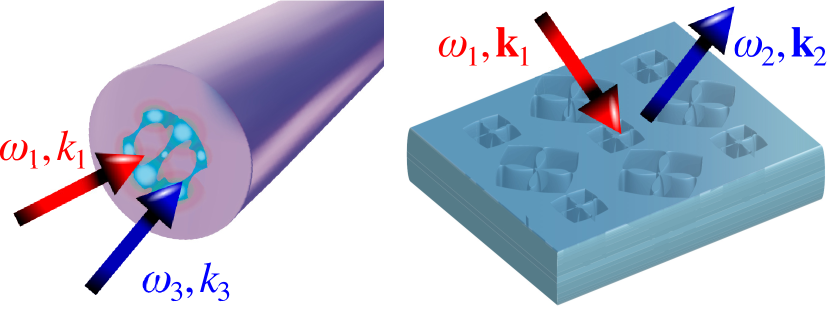
Our recently demonstrated optimization framework allows automatic discovery of novel cavities supporting tightly localized modes at several desired wavelengths and exhibiting large nonlinear mode overlaps. As a proof-of-concept, we proposed doubly-resonant structures, including multi-layered, aperiodic micro-post cavities and multi-track ring resonators, capable of realizing second-harmonic generation efficiencies exceeding Lin et al. (2016, 2017). In this paper, we extend and apply this optimization approach to design extended structures, including micro-structured optical fibers and photonic-crystal (PhC) metasurfaces as shown in Fig. 1, for achieving high-efficiency (second- and third-harmonic) frequency conversion. Harmonic generation, which underlies numerous applications in science, including coherent light sources Goldberg and Kliner (1995), optical imaging and microscopy Yelin (1999); Pantazis et al. (2010) and entangled-photon generation Hamel et al. (2010), is now feasible at lower power requirements thanks to the availability of highly nonlinear and materials such as III-V semiconductor compounds Rivoire et al. (2011b); Buckley et al. (2013) and novel types of chalcogenide glasses Hall et al. (1989). In combination with advances in materials synthesis, emerging fabrication technologies have also enabled demonstrations of sophisticated micro-structured fibers Ahmad et al. (2004) and metasurfaces Lapine et al. (2014); Campione et al. (2014); Lee et al. (2014); Wolf et al. (2015a); O Brien et al. (2015); Yang et al. (2015); Segal et al. (2015); Butet et al. (2015), paving the way for experimental realization of inverse-designed structures of increased geometric and fabrication complexity but which offer orders-of-magnitude enhancements in conversion efficiencies and the potential for augmented functionalities.
Given a material system of intrinsic or nonlinear coefficient, the efficiency of any given frequency-conversion process in a resonant geometry will be determined by a few modal parameters. The possibility of confining light within small mode volumes over long times or distances leads to significant gains in efficiency (i.e. lower power requirements), stemming from the higher intensity and cascadability of nonlinear interactions (compensating for the otherwise small bulk nonlinearities). In particular, the efficiency of such resonant processes depends on the product of mode lifetimes and a nonlinear coefficient , given by Eqs. (6) and (8) below, which generalizes the familiar concept of quasi-phase matching to situations that include wavelength-scale resonators Rodriguez et al. (2007). For propagating modes, leaky or guided, the existence of a propagation phase further complicates this figure of merit, with optimal designs requiring: (1) phase-matching and frequency-matching conditions, (2) large nonlinear mode overlaps and (3) large dimensionless lifetimes (low material absorption and/or radiative losses in the case of leaky modes). The main design challenge is the difficult task of forming a doubly resonant cavity with far-apart modes that simultaneously exhibit long lifetimes, large , along with phase and frequency matching. To date, the majority of prior works on frequency conversion in fibers Bétourné et al. (2008) and metasurfaces Li et al. (2017); Wolf et al. (2015a); Lee et al. (2014); Campione et al. (2014); Liu et al. (2016); Wolf et al. (2015b); Yang et al. (2015); Tymchenko et al. (2015), have focused on only one of these aspects (usually phase-matching) while ignoring the others. The geometries discovered by our optimization framework, in contrast, address the above criteria, revealing complex fibers and metasurfaces supporting TE or TM modes with guaranteed phase and frequency matching, long lifetimes and enhanced overlap factors at any desired propagation wavevector, and resulting in orders-of-magnitude enhancements in conversion efficiencies.
II An overview of optimization
The possibility of fine-tuning spatial features of photonic devices to realize functionalities not currently achievable by conventional optical design methodologies based on index guiding and band-gap confinement (which work exceedingly well but are otherwise limited for narrowband applications), has been a major drive behind the last several decades of interest in the topic of photonic optimization Joannopoulos et al. (2008). Among these techniques are probabilistic Monte Carlo algorithms, e.g. particle swarms, simulated annealing, and genetic algorithms Kim and O’Brien (2004); Darki and Granpayeh (2010); Minkov and Savona (2014). Though sufficient for majority of narrow-band (single-mode) applications, many of these gradient-free methods are limited to typically small sets of design parameters Gondarenko et al. (2006) which often prove inadequate for handling wide-band (multi-mode) problems. On the other hand, gradient-based inverse design techniques are capable of efficiently exploring a much larger design space by making use of analytical derivative information of the specified objective and constraint functions Jensen and Sigmund (2011). Recently, the development of versatile mathematical programming methods and the rapid growth in computational power have enabled concurrent progress in photonic inverse design, allowing theoretical (and more rencently, experimental) demonstrations of complex topologies and unintuitive geometries with unprecedented functionalities that would be arguably difficult to realize through conventional intuition alone. However, to date, most applications of inverse design in photonics are confined to linear devices such as mode converters, waveguide bends and beam splitters Gondarenko et al. (2006); Jensen and Sigmund (2011); Liang and Johnson (2013); Liu et al. (2013); Piggott et al. (2014); Men et al. (2014); Piggott et al. (2015); Shen et al. (2015). We believe that this paper along with our recent works Lin et al. (2016, 2017) provide a glimpse of the potential of photonic optimization in nonlinear optics.
A typical optimization problem seeks to maximize or minimize an objective function , subject to certain constraints , over a set of free variables or degrees of freedom (DOF) Strang (2007). Generally, one can classify photonic inverse design into two different classes of optimization strategies, based primarily on the nature or choice of DOF Deaton and Grandhi (2014). Given a computational domain or grid, the choice of a finite-dimensional parameter space not only determines the degree of complexity but also the convergence and feasibility of the solutions. One possibility is to exploit each DOF in the computational domain as an optimization parameter, known as topology optimization (TO), in which case one typically (though not always) chooses the dielectric permittivity of each pixel as a degree of freedom (known as a continuous relaxation parameter Bendsøe et al. (2004)). Another possibility, known as shape optimization, is to expand the optimization parameter space in a finite set of shapes (independent of the computational discretization), which may be freeform contours represented by so-called level sets Wang et al. (2003) (the level-set method) or basic geometric entities with simpler parametrizations (e.g. polytopes) Haslinger and Mäkinen (2003). In the level-set method, the zeros of a level-set “function” define the boundaries of “binary shapes”; the optimization then proceeds via a level-set PDE characterized by a velocity field which is, in turn, constructed from derivative information Wang et al. (2003). A much simpler variant (which we follow) is to choose a fixed but sufficient number of basic binary shapes whose parameters can be made to evolve by an optimization algorithm. Essentially, for such a parametrization, the mathematical representations of the shapes must yield continuous (analytic) derivatives, which is not feasible a priori due to the finite computational discretization and can instead be enforced by the use of a “smoothing Kernel” (described below).
A generic TO formulation is written down as:
| (1) | ||||
| (2) | ||||
| (3) |
where the DOFs are the normalized dielectric permittivities assigned to each pixel or voxel (indexed ) in a specified volume Jensen and Sigmund (2011); Liang and Johnson (2013). The subscript denotes appropriate spatial discretization with respect to Cartesian or curvilinear coordinates. Depending on the choice of background (bg) and structural materials, is mapped onto position-dependent dielectric constant via . The binarity of the optimized structure is enforced by penalizing the intermediate values or utilizing a variety of filter and regularization methods Jensen and Sigmund (2011). Starting from a random initial guess, the technique discovers complex structures automatically with the aid of powerful gradient-based algorithms such as the method of moving asymptotes (MMA) Svanberg (2002). For an electromagnetic problem, and are typically functions of the electric or magnetic fields integrated over some region, which are in turn solutions of Maxwell’s equations under some incident current or field. In what follows, we exploit direct solution of Maxwell’s equations,
| (4) |
describing the steady-state field in response to incident currents at frequency . While solution of (4) is straightforward and commonplace, the key to making optimization problems tractable is to obtain a fast-converging and computationally efficient adjoint formulation of the problem. Within the scope of TO, this requires efficient calculations of the derivatives at every pixel , which we perform by exploiting the adjoint-variable method (AVM) Jensen and Sigmund (2011).
While the TO technique is quite efficient in handling the enormity of an unconstrained design space, it often leads to geometries with irregular features that are difficult to fabricate. An alternative approach that is in principle more conducive to fabrication constraints is to exploit shape optimization. In this work, we primarily focus on a simple implementation of the latter that employs a small and hence limited set of elementary geometric shapes, e.g. ellipses Wang and Sigmund (2017) and polytopes, parametrized by a few DOFs. In particular, we express the dielectric profile of the computational domain as a sum of basic shape functions with permittivities, , described by shape functions and a finite set of geometric parameters , where denotes the shape index. Here, to deal with potential overlap of two or more shapes, we implement a filter function that enforces the same maximum-permittivity constraint described above. The derivatives of a given objective function (and associated constraints) can then be obtained via the chain rule , where the smoothness of the derivatives is guaranteed by insisting that the shape functions be continuously differentiable functions. Below, we choose non-piecewise-constant ellipsoidal shapes with exponentially varying dielectric profiles near the boundaries, the smoothness of which is determined by a few simple parameters that can, at various points along the optimization, be slowly adjusted to realize fully binary structures upon convergence. Such a “relaxation” process Haslinger and Mäkinen (2003) is analogous to the application of a binary filter in the objective function Jensen and Sigmund (2011).
Any NFC process can be viewed as a frequency mixing scheme in which two or more constituent photons at a set of frequencies interact to produce an output photon at frequency , where can be either negative or positive, depending on whether the corresponding photons are created or destroyed in the process Boyd (1992). Given an appropriate nonlinear tensor component , with , mediating an interaction between the polarization components and , , we begin with a collection of point dipole currents, each at the constituent frequency , such that , where is a polarization vector chosen so as to excite the desired electric-field polarization components () of the corresponding mode at an appropriate position . Given the choice of incident currents , we solve Maxwell’s equations to obtain the corresponding constituent electric-field response , from which one can construct a nonlinear polarization current , where and can be generally polarized () in a (chosen) direction that differs from the constituent polarizations . Here, (*) denotes complex conjugation for negative and no conjugation otherwise. Finally, maximizing the radiated power, , due to , one is immediately led to the following nonlinear optimization problem:
| (5) | ||||
where is given by either the topology or shape parameterizations described above. Writing down the objective function in terms of the nonlinear polarization currents, it follows that solution of (5), obtained by employing any mathematical programming technique that makes use of gradient information, e.g. the adjoint variable method Jensen and Sigmund (2011), maximizes the nonlinear coefficient (mode overlap) associated with the aforementioned nonlinear optical process. The above framework can be easily extended to consider propagating modes once we take into account the appropriate Bloch boundary conditions that may arise from any desired wave vectors imposed at the requisite frequencies Taflove and Hagness (2000). In the case of optical fibers or PhC metasurfaces (or, more generally, any waveguiding system), such an extension naturally guarantees perfect phase- and frequency-matching of the relevant modes in the optimized structure.
III Third harmonic generation in fibers
Conventional microstructured fibers (e.g. Bragg and holey fibers) are typically designed based on intuitive principles like index-guiding and bandgap confinement Joannopoulos et al. (2008), and thus often consist of periodic cross-sections comprising simple shapes Temelkuran et al. (2002); Feng et al. (2003). Below, we apply the aforementioned optimization techniques to propose much more complicated heterostructure fibers designed to enhance third-harmonic generation at any desired wavelength. In order to achieve large third-harmonic generation efficiencies, the fiber must support two co-propagating modes of frequencies and and wavenumbers satisfying the phase-matching condition . Furthermore, the system must exhibit low radiative/dissipative losses or alternatively, attenuation lengths that are much longer than the corresponding interaction lengths , defined as the propagation length at which 50% of the fundamental mode is up-converted. In the small-input signal regime, the converted, third-harmonic output power and the interaction length depend on the incident power , vacuum impedance and nonlinear overlap factor Grubsky and Savchenko (2005),
| (6) |
which involves a complicated spatial overlap of the two modes over the cross-sectional surface of the fiber. Note that the attenuation coefficient of each mode (the inverse of their respective attenuation length) is proportional to their lifetime and group velocity .
We focus on fibers comprising Chalcogenide/PES composites of permittivities and at telecom wavelengths. Although our technique can be readily applied to design the requisite properties at any given wavenumber and for any desired polarization, we specifically focus on designs for operation at wavenumbers in the range , with denoting the corresponding vacuum wavelength and the optimized wavenumber. We consider both leaky and guided modes above and below the PES light line , respectively, along with different choices or transverse electric and transverse magnetic polarizations. modes are those polarized along the plane of the fiber and consist primarily of circulating and electric fields Agrawal (2012), while modes have electric fields polarized mainly along the propagation direction .
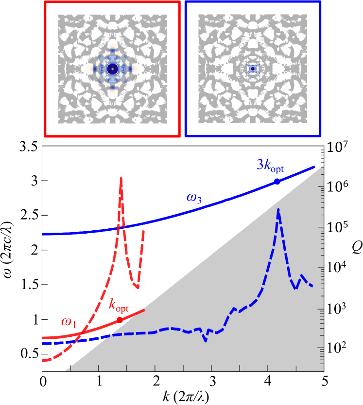
Figure 2 (top insets) shows an inverse-designed fiber cross-section that supports phased-matched fundamental and third-harmonic modes (with profiles superimposed on the insets) at . To ensure that the optimization algorithm selectively finds modes, we employ a magnetic current as the source in (5), resulting in electric fields of the desired polarization. The fiber cross-section is represented by a computational cell consisting of pixels, where the size of each pixel is . From Figure 2 (inset), it is clear that both the fundamental and third harmonic modes are well confined to the fiber core and exhibit substantial modal overlaps, while again, the phase-matching condition is automatically satisfied by the optimization process, with . We find that is almost four orders of magnitude larger than what has been demonstrated in standard plain fibers, which have typical values of Grubsky and Savchenko (2005). Figure 2 shows the dispersion of the two leaky modes (solid lines), with the PES lightline represented by the gray region and their corresponding dimensionless lifetimes, around and at , plotted as dashed lines. Noticeably, while the fiber is optimized to ensure phase matching at a single , any phase mismatch remains small in the vicinity of . In fact, even for , the frequency difference is found to be only around . Technically the only factor limiting the lifetimes is the finite computational cross-section (imposed by the finite computational cell), with much larger lifetimes possible for larger cross sections. Away from , the quality factors decrease while remaining relatively large over a wide range of . Considering the group velocity around , we find that the attenuation length of the fiber . We note that while the fiber supports mutliple modes around these wavelengths, the only modes near are those discovered by the optimization and shown in the figure.
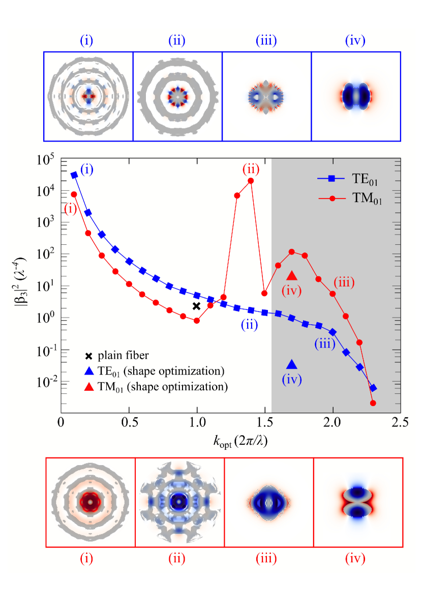
Figure 3 shows the corresponding to fibers optimized for operation at different values of and polarizations, and obtained by application of either topology (squares) or shape (triangles) optimization. The figure shows a general trend in which decreases with increasing for both polarizations, except that fibers tend to exhibit non-monotonic behavior, with increasing sharply at an intermediate below the lightline, above which it drops significantly before increasing again in the guided regime, peaking again at before plummeting once again. We suspect that this complicated behavior is not a consequence of any fundamental limitation or physical consideration, but rather stems from the optimization algorithm getting stuck in local minima. Regardless, our results provide a proof-of-principle of the existence of fiber designs with performance characteristics that can greatly surpass qthose of traditional, hand-designed fibers. Furthermore, Fig. 3 shows typical fiber cross-sections at selective , along with their corresponding superimposed (fundamental) mode profiles, illustrating the fabricability of the structures.
| Structure | () | ||
|---|---|---|---|
| gold split resonators Campione et al. (2014) | 250 | 10 | |
| gold split resonators Wolf et al. (2015b) | 1.3 | 3.4 | * |
| gold cross bars Lee et al. (2014) | 54 | 8 | * |
| all-dielectric cylinders Liu et al. (2016) | 0.2 | 1.02 | * |
| optimized design [Fig. 4] | 0.1 | 1.2 |
Finally, we provide estimates of the power requirements associated with these fiber designs. We find that for a fiber operating at and at a wavelength of m, conversion efficiencies of can be attained at relatively small pump powers over a fiber segment , while the corresponding (radiative) attenuation lengths are cm. For comparison, plain silica fibers Grubsky and Savchenko (2005) exhibit mode-overlap factors , leading to conversion efficiencies on the order of for the same input power and fiber length. Hence, the optimized structures achieve considerably ( times) higher conversion efficiencies, an improvement that is only partially due to the larger of ChG compared to glass (approximately times larger). In particular, defining the normalized interaction fiber length , which removes any source of material enhancement, we find that the optimized fiber leads to a factor of enhancement. Similarly, we find that a fiber operating at results in a factor of enhancement compared to plain fibers.
IV Second harmonic generation in metasurfaces
Metasurfaces offer an advantageous platform for realizing complicated beam generation and wavefront shaping over extended surfaces Yu and Capasso (2014) and have recently been exploited in conjunction with nonlinear materials as a means of generating and controlling light at multiple wavelengths Li et al. (2017); Michaeli et al. (2017); Keren-Zur et al. (2015); Segal et al. (2015). A typical nonlinear metasurfaces can suffer from poor frequency-conversion efficiencies due to a combination of weak confinement, material absorption, and sub-optimal mode overlaps. In particular, typical designs exploit plasmonic Campione et al. (2014); Wolf et al. (2015b); Lee et al. (2014); Wolf et al. (2015a) or all-dielectric Liu et al. (2016); Yang et al. (2015) elements comprising simple shapes distributed over a unit cell, including split ring resonators Campione et al. (2014); Wolf et al. (2015a, b), cross-bars Lee et al. (2014), and cylindrical posts Liu et al. (2016), with the main focus being that of satisfying the requisite frequency- and phase-matching condition Krasnok et al. (2017). Here, we show that inverse design can not only facilitate the enforcement of frequency- and phase-matching requirements but also allow further enhancements stemming from the intentional engineering of nonlinear modal overlaps, often neglected in typical designs.
To achive large second-harmonic generation efficiencies, a metasurface must support two extended resonances at frequencies and and wavevectors satisfying the phase-matching condition . As illustrated schematically in Fig. 4, a typical setup consists of an incident wave of power per unit cell at some frequency and angle (described by wavenumber ) and a corresponding output harmonic wave of power per unit cell, . In the small-signal regime, the output power scales quadratically with , resulting in a conversion efficiency per unit cell,
| (7) |
where and denote total and radiative dimensionless lifetimes and the nonlinear overlap factor,
| (8) |
Note that the conversion efficiency is defined as the efficiency per unit cell, since we are dealing with an extended surface.
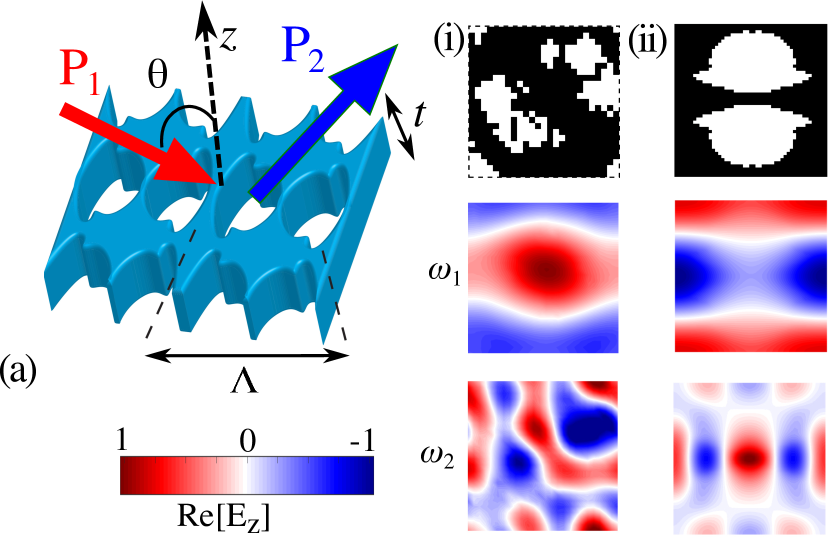
We now apply our optimization framework to discover new all-dielectric metasurfaces, with the permittivity of the medium taken to be that of gallium phospide near telecom wavelengths Bond (1965); Shoji et al. (1997). Note, however, that the same framework can be easily extended to design plasmonic surfaces. The metasurfaces, illustrated schematically in Fig. 4, are square photonic-crystal slabs of in-plane periodcity and finite thickness . To ensure fabricability, the optimization parameters are taken to lie in the plane of the metasurface, resulting in structures that can be fabricated by etching.
Figure 4 shows cross-sections of the unit cell of two GaP metasurfaces of thicknesses nm and nm, designed for operation at a fundamental frequency rad/s ( m) so as to satisfy both frequency- and phase-matching conditions. Also shown are the corresponding fundamental and harmonic mode profiles. The structure on the left is optimized for operation at an incident angle relative to the out-of-plane axis and is found to exhibit large radiative lifetimes and overlap factor . The structure on the right is instead optimized for operation at normal incidence, resulting in a slightly smaller . Due to the symmetry of the structure, the modes exhibit infinite lifetimes (and hence are technically dark modes), though in practice, fabrication imperfections necessarily lead to finite lifetimes. Table 1 compares a few of the relevant figures of merits for representative metasurface designs, which include both plasmonic and dielectric structures. Although comparing appears to be impossible due to a surprising lack of relevant modal parameters in these studies Campione et al. (2014); Wolf et al. (2015b); Lee et al. (2014); Liu et al. (2016). including the absence of radiative and dissipative quality factors, we find that the optimized designs exhibit orders of magnitude larger conversion efficiencies. While it is difficult to distinguish the relative impact of the mode lifetimes and overlap factors, arguably, the optimized structures overcome several limitations associated with previous designs. On the one hand, plasmonic structures exhibit tightly confined modes and therefore lead to large nonlinear overlaps, but absorptive losses and weak material nonlinearities imply that they suffer from small lifetimes. On the other hand, several of the proposed all-dielectric metasurfaces have had negligible material losses and hence larger lifetimes, but have not been designed to ensure large nonlinear overlaps.
V Concluding Remarks
We have demonstrated a novel optimization approach for the design of nonlinear photonic fibers and metasurfaces. The optimized structures demonstrate very high leaky-mode lifetimes for both fundamental and harmonic modes and order-of-magnitude larger overlap factors than traditional designs. Inverse design not only overcomes efficiency limitations of traditional index fibers and photonic crystal metasurfaces but also greatly reduces challenges and difficulties inherent to the design process. Although in this report we have not considered effects resulting from self- or cross-phase modulation, we expect no significant impact on the conversion efficiency in the small-signal limit since the finite bandwidth around the designated phase-matched propagation wavevectors can potentially compensate for any small phase-mismatch that might arise. At larger powers where these effects cannot be ignored, one could account and compensate for them through minor modifications to the optimization objective function, the subject of future work. Furthermore, we will consider extending our inverse design framework to terahertz frequency generation and other novel nonlinear processes.
VI Acknowledgements
This material is based upon work supported by the National Science Foundation under Grant No. DMR-1454836, a MRSEC supported by NSF Grant No. DMR 1420541, and NSF Award EFMA-1640986.
References
- DeLong et al. (1994) K. W. DeLong, R. Trebino, J. Hunter, and W. E. White, J. Opt. Soc. Am. B 11, 2206 (1994).
- Arbore et al. (1997) M. A. Arbore, A. Galvanauskas, D. Harter, M. H. Chou, and M. M. Fejer, Opt. Lett. 22, 1341 (1997).
- Heinz et al. (1982) T. F. Heinz, C. K. Chen, D. Ricard, and Y. R. Shen, Phys. Rev. Lett. 48, 478 (1982).
- Kuo et al. (2006) P. S. Kuo, K. L. Vodopyanov, M. M. Fejer, D. M. Simanovskii, X. Yu, J. S. Harris, D. Bliss, and D.Weyburne, Opt. Lett. 31, 71 (2006).
- Vodopyanov et al. (2006) K. L. Vodopyanov, M. M. Fejer, X. Yu, J. S. Harris, Y.-S. Lee, W. C. Hurlbut, V. G. Kozlov, D. Bliss, and C. Lynch, Appl. Phys. Lett. 89, 141119 (2006).
- Krischek et al. (2010) R. Krischek, W. Wieczorek, A. Ozawa, N. Kiesel, P. Michelberger, T. Udem, and H. Weinfurter, Nature Photonics 4, 170 (2010).
- Vaziri et al. (2002) A. Vaziri, G. Weihs, and A. Zeilinger, Phys. Rev. Lett. 89, 240401 (2002).
- Tanzilli et al. (2005) S. Tanzilli, W. Tittel, M. Halder, O. Alibart, P. Baldi, N. Gisin, and H. Zbinden, Nature 437, 116 (2005).
- Zaske et al. (2012) S. Zaske, A. Lenhard, C. A. Keßler, J. Kettler, C. Hepp, C. Arend, R. Albrecht, W.-M. Schulz, M. Jetter, P. Michler, and C. Becher, Phys. Rev. Lett. 109, 147404 (2012).
- Fürst et al. (2010) J. U. Fürst, D. V. Strekalov, D. Elser, M. Lassen, U. L. Andersen, C. Marquardt, and G. Leuchs, Phys. Rev. Lett. 104, 153901 (2010).
- Fejer (1994) M. M. Fejer, Physics today 47, 25 (1994).
- Soljačić and Joannopoulos (2004) M. Soljačić and J. D. Joannopoulos, Nature materials 3, 211 (2004).
- Dumeige and Feron (2006) Y. Dumeige and P. Feron, Phys. Rev. A 74, 063804 (2006).
- Wu et al. (1987) L.-A. Wu, M. Xiao, and H. J. Kimble, JOSA-B 4, 1465 (1987).
- Simonneau et al. (1997) C. Simonneau, J. P. Debray, J. C. Harmand, P. Vidaković, D. J. Lovering, and J. A. Levenson, Opt. Lett. 22, 1775 (1997).
- Paschotta et al. (1994) R. Paschotta, K. Fiedler, P. Kurz, and J. Mlynek, Appl. Phys. Lett. 58, 117 (1994).
- Koch and Moore (1999) K. Koch and G. T. Moore, J. Opt. Soc. Am. B 16, 448 (1999).
- Liscidini and Andreani (2004) M. Liscidini and L. A. Andreani, Appl. Phys. Lett. 85, 1883 (2004).
- Rivoire et al. (2011a) K. Rivoire, S. Buckley, and J. Vuckovic, Appl. Phys. Lett. 99, 013114 (2011a).
- Ramirez et al. (2011) D. Ramirez, A. W. Rodriguez, H. Hashemi, J. D. Joannopoulos, M. Solijacic, and S. G. Johnson, Phys. Rev. A 83, 033834 (2011).
- Lin et al. (2014) Z. Lin, T. Alcorn, M. Loncar, S. Johnson, and A. Rodriguez, Phys. Rev. A 89, 053839 (2014).
- Pernice et al. (2012) W. H. P. Pernice, C. Xiong, C. Schuck, and H. X. Tang, Applied Physics Letters 100, 223501 (2012), http://dx.doi.org/10.1063/1.4722941.
- Bi et al. (2012) Z.-F. Bi, A. W. Rodriguez, H. Hashemi, D. Duchesne, M. Loncar, K.-M. Wang, and S. G. Johnson, Opt. Express 20, 7526 (2012).
- Rivoire et al. (2009) K. Rivoire, Z. Lin, F. Hatami, W. T. Masselink, and J. Vučković, Opt. Express 17, 22609 (2009).
- Buckley et al. (2014) S. Buckley, M. Radulaski, J. L. Zhang, J. Petykiewicz, K. Biermann, and J. Vučković, Opt. Express 22, 26498 (2014).
- Rodriguez et al. (2007) A. Rodriguez, M. Soljačić, J. D. Joannopulos, and S. G. Johnson, Opt. Express 15, 7303 (2007).
- Lin et al. (2016) Z. Lin, X. Liang, M. Lončar, S. G. Johnson, and A. W. Rodriguez, Optica 3, 233 (2016).
- Lin et al. (2017) Z. Lin, M. Lončar, and A. W. Rodriguez, arXiv preprint arXiv:1701.05628 (2017).
- Goldberg and Kliner (1995) L. Goldberg and D. A. V. Kliner, Opt. Lett. 20, 1640 (1995).
- Yelin (1999) Y. Yelin, D.and Silberberg, Opt. Express 5, 169 (1999).
- Pantazis et al. (2010) P. Pantazis, J. Maloney, D. Wu, and S. E. Fraser, Proceedings of the National Academy of Sciences 107, 14535 (2010).
- Hamel et al. (2010) D. R. Hamel, A. Fedrizzi, S. Ramelow, K. J. Resch, and T. Jennewein, Nature 466, 601 (2010).
- Rivoire et al. (2011b) K. Rivoire, S. Buckley, F. Hatami, and J. Vuckovic, Appl. Phys. Lett. 98, 263113 (2011b).
- Buckley et al. (2013) S. Buckley, M. Radulaski, K. Biermann, and J. Vuckovic, ArXiv:1308.6051v1 (2013).
- Hall et al. (1989) D. W. Hall, M. A. Newhouse, N. F. Borrelli, W. H. Dumbaugh, and D. L. Weidman, Applied Physics Letters 54, 1293 (1989).
- Ahmad et al. (2004) R. Ahmad, M. Soljacic, M. Ibanescu, T. Engeness, M. Skorobogatly, S. Johnson, O. Weisberg, Y. Fink, L. Pressman, W. King, et al., “High index-contrast fiber waveguides and applications,” (2004), uS Patent 6,788,864.
- Lapine et al. (2014) M. Lapine, I. V. Shadrivov, and Y. S. Kivshar, Reviews of Modern Physics 86, 1093 (2014).
- Campione et al. (2014) S. Campione, A. Benz, M. B. Sinclair, F. Capolino, and I. Brener, Applied Physics Letters 104, 131104 (2014).
- Lee et al. (2014) J. Lee, M. Tymchenko, C. Argyropoulos, P.-Y. Chen, F. Lu, F. Demmerle, G. Boehm, M.-C. Amann, A. Alu, and M. A. Belkin, Nature 511, 65 (2014).
- Wolf et al. (2015a) O. Wolf, S. Campione, A. Benz, A. P. Ravikumar, S. Liu, T. S. Luk, E. A. Kadlec, E. A. Shaner, J. F. Klem, M. B. Sinclair, et al., Nature communications 6 (2015a).
- O Brien et al. (2015) K. O Brien, H. Suchowski, J. Rho, A. Salandrino, B. Kante, X. Yin, and X. Zhang, Nature materials 14, 379 (2015).
- Yang et al. (2015) Y. Yang, W. Wang, A. Boulesbaa, I. I. Kravchenko, D. P. Briggs, A. Puretzky, D. Geohegan, and J. Valentine, Nano letters 15, 7388 (2015).
- Segal et al. (2015) N. Segal, S. Keren-Zur, N. Hendler, and T. Ellenbogen, Nature Photonics 9, 180 (2015).
- Butet et al. (2015) J. Butet, P.-F. Brevet, and O. J. Martin, ACS nano 9, 10545 (2015).
- Bétourné et al. (2008) A. Bétourné, Y. Quiquempois, G. Bouwmans, and M. Douay, Opt. Express 16, 14255 (2008).
- Li et al. (2017) G. Li, S. Zhang, and T. Zentgraf, Nature Reviews Materials 2, natrevmats201710 (2017).
- Liu et al. (2016) S. Liu, M. B. Sinclair, S. Saravi, G. A. Keeler, Y. Yang, J. Reno, G. M. Peake, F. Setzpfandt, I. Staude, T. Pertsch, et al., Nano letters 16, 5426 (2016).
- Wolf et al. (2015b) O. Wolf, A. A. Allerman, X. Ma, J. R. Wendt, A. Y. Song, E. A. Shaner, and I. Brener, Applied Physics Letters 107, 151108 (2015b).
- Tymchenko et al. (2015) M. Tymchenko, J. S. Gomez-Diaz, J. Lee, N. Nookala, M. A. Belkin, and A. Alù, Physical review letters 115, 207403 (2015).
- Joannopoulos et al. (2008) J. D. Joannopoulos, S. G. Johnson, J. N. Winn, and R. D. Meade, Photonic Crystals: Molding the Flow of Light, 2nd ed. (Princeton University Press, 2008).
- Kim and O’Brien (2004) W. J. Kim and J. D. O’Brien, J. Opt. Soc. Am. B 21, 289 (2004).
- Darki and Granpayeh (2010) B. S. Darki and N. Granpayeh, Optics Communications 283, 4099 (2010).
- Minkov and Savona (2014) M. Minkov and V. Savona, Sci. Rep. 4 (2014).
- Gondarenko et al. (2006) A. Gondarenko, S. Preble, J. Robinson, L. Chen, H. Lipson, and M. Lipson, Phys. Rev. Lett. 96, 143904 (2006).
- Jensen and Sigmund (2011) J. Jensen and O. Sigmund, Laser and Photonics Reviews 5, 308 (2011).
- Liang and Johnson (2013) X. Liang and S. G. Johnson, Opt. Express 21, 30812 (2013).
- Liu et al. (2013) D. Liu, L. H. Gabrielli, M. Lipson, and S. G. Johnson, Opt. Express 21, 14223 (2013).
- Piggott et al. (2014) A. Y. Piggott, J. Lu, T. M. Babinec, K. G. Lagoudakis, J. Petykiewicz, and J. Vuckovic, Sci. Rep. 4 (2014).
- Men et al. (2014) H. Men, K. Y. K. Lee, R. M. Freund, J. Peraire, and S. G. Johnson, Optics Express 22, 22632 (2014), arXiv:1405.4350 .
- Piggott et al. (2015) A. Y. Piggott, J. Lu, K. G. Lagoudakis, J. Petykiewicz, T. M. Babinec, and J. Vuckovic, Nature Photonics 9, 374 (2015).
- Shen et al. (2015) B. Shen, P. Wang, and R. Menon, Nature Photonics 9, 378 (2015).
- Strang (2007) G. Strang, Computational science and engineering, Vol. 791 (Wellesley-Cambridge Press Wellesley, 2007).
- Deaton and Grandhi (2014) J. D. Deaton and R. V. Grandhi, Structural and Multidisciplinary Optimization 49, 1 (2014).
- Bendsøe et al. (2004) M. P. Bendsøe, O. Sigmund, M. P. Bendsøe, and O. Sigmund, Topology optimization by distribution of isotropic material (Springer, 2004).
- Wang et al. (2003) M. Y. Wang, X. Wang, and D. Guo, Computer methods in applied mechanics and engineering 192, 227 (2003).
- Haslinger and Mäkinen (2003) J. Haslinger and R. A. Mäkinen, Introduction to shape optimization: theory, approximation, and computation (SIAM, 2003).
- Svanberg (2002) K. Svanberg, SIAM Journal on Optimization , 555 (2002).
- Wang and Sigmund (2017) F. Wang and O. Sigmund, in Numerical Simulation of Optoelectronic Devices (NUSOD), 2017 International Conference on (IEEE, 2017) pp. 39–40.
- Boyd (1992) R. W. Boyd, Nonlinear Optics (Academic Press, California, 1992).
- Taflove and Hagness (2000) A. Taflove and S. C. Hagness, Computational Electrodynamics: The Finite-Difference Time-Domain Method (Artech, Norwood, MA, 2000).
- Temelkuran et al. (2002) B. Temelkuran, S. D. Hart, G. Benoit, J. D. Joannopoulos, and Y. Fink, Nature 420, 650 (2002).
- Feng et al. (2003) X. Feng, T. Monro, P. Petropoulos, V. Finazzi, and D. Hewak, Opt. Express 11, 2225 (2003).
- Grubsky and Savchenko (2005) V. Grubsky and A. Savchenko, Opt. Express 13, 6798 (2005).
- Agrawal (2012) G. P. Agrawal, Fiber-optic communication systems, Vol. 222 (John Wiley & Sons, 2012).
- Yu and Capasso (2014) N. Yu and F. Capasso, Nature materials 13, 139 (2014).
- Michaeli et al. (2017) L. Michaeli, S. Keren-Zur, O. Avayu, H. Suchowski, and T. Ellenbogen, Physical Review Letters 118, 243904 (2017).
- Keren-Zur et al. (2015) S. Keren-Zur, O. Avayu, L. Michaeli, and T. Ellenbogen, ACS Photonics 3, 117 (2015).
- Krasnok et al. (2017) A. Krasnok, M. Tymchenko, and A. Alù, arXiv preprint arXiv:1706.07563 (2017).
- Bond (1965) W. Bond, Journal of Applied Physics 36, 1674 (1965).
- Shoji et al. (1997) I. Shoji, T. Kondo, A. Kitamoto, M. Shirane, and R. Ito, JOSA B 14, 2268 (1997).