Optical activity in chiral stacks of 2D semiconductors
Abstract
We show that the stacks of two-dimensional semiconductor crystals with the chiral packing exhibit optical activity and circular dichroism. We develop a microscopic theory of these phenomena in the spectral range of exciton transitions which takes into account the spin-dependent hopping of excitons between the layers in the stack and the interlayer coupling of excitons via electromagnetic field. For the stacks of realistic two-dimensional semiconductors such as transition metal dichalcogenides, we calculate the rotation and ellipticity angles of radiation transmitted through such structures. The angles are resonantly enhanced at the frequencies of both bright and dark exciton modes in the stack. We also study the photoluminescence of chiral stacks and show that it is circularly polarized.
pacs:
Valid PACS appear hereI Introduction
Optical activity, the ability of certain media to rotate the plane of light polarization in the absence of a magnetic field, is a remarkable manifestation of polarization dependent interaction between light and matter Goldstein (2011). It stems from the different strengths of coupling to right-handed and left-handed circularly polarized light leading to circular birefringence and circular dichroism Kaminsky (2000). From the pioneering experiment by J.C. Bose in 1898 with left- and right-twisted jute elements Bose (1898), the optical rotation is commonly associated with chirality. Optically active media attract much attention because they allow one to manipulate the polarization state of light. This is particularly important for superresolution imaging and the development of broadband optical components, such as filters and sensors with high polarization suppression ratio Wang et al. (2017); Chadha et al. (2014). Moreover, the photon polarization is currently considered as the degree of freedom to code and carry quantum information Bennett et al. (1992).
Optical activity, also referred to as gyrotropy, can be of either intrinsic or extrinsic nature. The former occurs in macroscopically homogeneous systems with chiral molecule components or crystals of the gyrotropic symmetry classes Kizel’ et al. (1975). A canonical example of optically active biological media is the tartaric acid, which was discovered by L. Pasteur and explained by the predominance of one of the two possible stereoisomers of the acid molecules Mason (1982). Tellurium is an example of gyrotropic crystals Nomura (1960). This elemental semiconductor can exist in two enantiomorphic forms with the atoms, constituting the crystal lattice, bound into left-handed or right-handed chains. An example of gyrotropic but not chiral bulk crystals is silver gallium sulphide Hobden (1967). Microscopically, optical activity originates from the spatial dispersion of susceptibility Agranovich and Ginzburg (2013). It is increased in the vicinity of exciton resonances, as was observed in bulk wurtzite crystals lvchenko and Sel’kin (1979) and II-VI quantum well structures Kotova et al. (2016). The term “extrinsic optical activity” coined recently is primarily used for metamaterials, metasurfaces, and photonic crystals composed of the arrays of chiral or achiral elements such as gammadions Rogacheva et al. (2006); Lobanov et al. (2015); Demenev et al. (2016), G-shape nanostructures Mamonov et al. (2014), and split-ring resonators Plum et al. (2009). The efficiency of polarization conversion can be enhanced by plasmonic resonances in metal nanostructures Minovich et al. (2015); Collins et al. (2017).
Apart from the above two distinct types of gyrotropic structures, we highlight the opportunity of an intermediate case of artificial materials with chiral stacking of atomic layers. Previously, they would be hypothetical. The emerging technology of van der Waals structures made of two-dimensional (2D) crystals of atomic thickness Geim and Grigorieva (2013); Lotsch (2015) enables the formation of such materials. Recently, it has been experimentally demonstrated that a pair of graphene layers stacked with a twist exhibits the optical activity Kim et al. (2016). The optical rotation angle normalized to the sample thickness was found to be several orders of magnitude larger than that in natural materials. The 2D crystals beyond the graphene, such as transition metal dichalcogenides (TMDC) MoS2, WS2, etc., are of particular interest for application in optics. TMDC layers have optical gaps and demonstrate strong light-matter coupling in the spectral range of exciton transitions Mak et al. (2010); Mak and Shan (2016); Cadiz et al. (2017); Jun et al. (2017). Pronounced exciton resonances have been observed in the reflectance spectra of TMDC layers and thin films Arora et al. (2015); Koperski et al. (2017). The properties of twisted stacks including the interlayer coupling strength are also being widely studied Liu et al. (2014); Huang et al. (2014); van der Zande et al. (2014); Yan et al. (2015); Plechinger et al. (2015); Xia et al. (2017). At the same time, the optical polarization effects related to chirality slipped away from the focus of previous research.
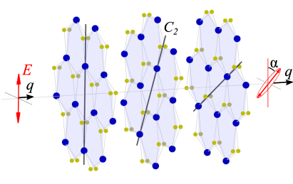
In this paper, we study the optical properties of chiral stacks of 2D gapped crystals. We show that properly arranged stacks (see Fig. 1) exhibit pronounced optical activity while individual layers do not. We develop a microscopic theory of the optical activity and the accompanying phenomenon of circular dichroism. It is also predicted that the photoluminescence of chiral stacks is circularly polarized.
The paper is organized as follows. In Sec. II, we develop a theoretical approach to describe the exciton states in the chiral stacks of TMDC layers and the polarization optical properties of such stacks. We start by considering chiral bilayers and then generalize the model to multi-layer stacks. In Sec. III, we describe the spectral behavior of light transmission, optical activity, and circular dichroism for the chiral bilayers, multi-layers, and thick TMDC stacks. In Sec. IV, we discuss the circularly polarized photoluminescence of chiral stacks. Section V summarizes the results of the paper.
II Model
The spatial symmetry of a single TMDC layer is described by the point group. The layers are optically inactive and demonstrate isotropic linear response at the normal incident of radiation. We consider the optical response associated with bright direct excitons with the spin projections along the normal to the layer which are excited by the circularly polarized light, respectively. The excitons are formed by electrons and holes located at the and valleys of the two-dimensional Brillouin zone. The exciton states with the spin projections at zero in-plane wave vector are degenerate in energy.
Arranging two TMDC layers into a twisted stack reduces the point-group symmetry of the system to . The exciton states in such a bilayer are described by an effective Hamiltonian , where stand for the monolayer index and stand for the spin index. We note that, in multi-layer systems, there are also excitations consisting of electrons and holes localized in different layers Arora et al. (2017); Nagler et al. (2017). Those interlayer excitons are far separated in energy from the intralayer excitons because of the reduced Coulomb interaction and are not considered here.
The point group of the bilayer imposes restrictions on the form of the effective exciton Hamiltonian. The presence of the three-fold rotation axis along the bilayer normal eliminates the matrix elements of the Hamiltonian with , so that . The two-fold rotation axes lying in the bilayer plane impose the constraints and . Finally, the time-reversal symmetry requires . Combining all the above symmetry constraints together with the requirement that the Hamiltonian is Hermitian we arrive to the most general form of the exiton Hamiltonian in a chiral bilayer
| (3) |
with real parameters , , and . Here, is the exciton frequency in an isolated layer, describes the interlayer hopping of excitons due to, e.g., tunneling or Förster excitation transfer, and is the phase acquired at the interlayer hopping due to the chirality of the bilayer. The Planck constant is set to unity. The dependence of the phase on the parameters of particular TMDC bilayers can be obtained from microscopic calculations which are beyond the scope of the present paper. Instead, we focus below on the general optical properties of chiral bilayers and multi-layers. We only note that the phase vanishes in achiral stacks which are realized at the twist angle 0, , , etc.
The model above can be readily generalized to the chiral stack of layers. Assuming the hopping of excitons between the nearest-neighbor layers only, we shall use the exciton Hamiltonian with the matrix elements
| (4) |
with .
Now we consider the interaction of excitons with the electromagnetic field. Due to high symmetry of an individual layer, the strength of exciton-photon coupling in a layer is described by a single parameter which determines the exciton radiative decay rate. For the incident light propagating along the axis (Fig. 1), the exciton polarizations in the layers are determined by the equation set (see Ref. Ivchenko (2005))
| (5) |
where is the electric field amplitude of the incident radiation with a certain helicity, and are the photon frequency and wave vector, respectively, is the position of the -th layer, and is the interlayer distance. The last term in the left-hand side of Eq. (II) describes both the radiative decay of excitons (at ) and the radiative coupling of excitons in different layers (at ). Equation (II) also takes into account the non-radiative decay of excitons with the rate Ivchenko et al. (1994); Poshakinskiy et al. (2012); Kazanov et al. (2017).
The amplitude of a circularly polarized electromagnetic wave transmitted through the stack is given by
| (6) |
By solving Eqs. (II) we calculate and the amplitude transmission coefficients for the right-handed and left-handed circularly polarized radiation .
Consider now the transmission of linearly polarized light through the chiral stack. The spectrum of transmission is determined by
| (7) |
Due to the difference in the transmission coefficients and , the linearly polarized light, when transmitted through the stack, rotates its polarization plane (optical activity) and acquires ellipticity (circular dichroism). The corresponding rotation angle and ellipticity angle are defined by
| (8) |
At , the rotation and ellipticity angles are small and Eq. (8) can be rewritten in the compact form
| (9) |
Below, we use these relations to analyze optical activity and circular dichroism in bilayers and multi-layer stacks.
III Results and discussion
III.1 Chiral bilayer
In a bilayer, the interlayer hopping of excitons leads to the formation of the symmetric and antisymmetric exciton modes denoted by the numbers and , respectively 111The eigen exciton modes are strictly symmetric or antisymmetric only at .. Each of them is two-fold degenerate in the spin index . Diagonalization of the Hamiltonian (3) yields the eigen frequencies of the modes
| (10) |
and the eigen functions
| (15) |
The symmetric (bright) mode is efficiently coupled to the electromagnetic field while the coupling of the antisymmetric (dark) mode to the field is very weak Ivchenko (2005); Ivchenko et al. (1994).
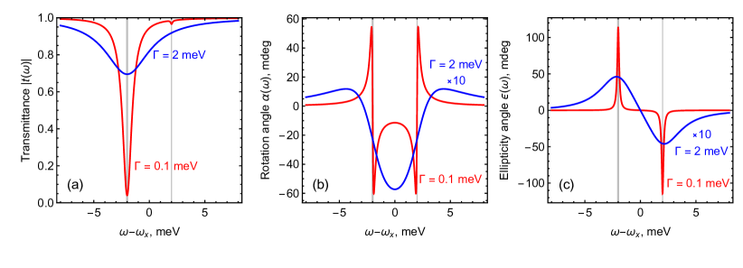
Figure 2a shows the transmission spectra of linearly polarized light for the chiral bilayers. Red and blue curves correspond to the cases of low and high non-radiative exciton decay rate . The frequencies of the symmetric and antisymmetric exciton modes are indicated by vertical lines. The transmission spectra feature a single dip at the frequency of the symmetric mode with a barely noticeable trace of the antisymmetric mode.
At , the symmetric and antisymmetric modes are well separated in frequency and do not interact with each other. It follows from Eq. (II) that the interaction of an individual exciton mode with the circularly polarized light propagating along the axis () or in the opposite direction () is characterized by the rates
| (16) |
where are the components of the columns (15). In particular, the rates of exciton-photon interaction in a bilayer are given by
| (17) | ||||
The total radiative decay rate of excitons in the mode () is . The symmetric exciton mode is supperradiant and is coupled to light twice stronger than the exciton mode in a single layer. The width of the dip in the transmission spectrum (Fig. 2a) associated with the symmetric exciton mode is about Ivchenko et al. (1994); Poshakinskiy et al. (2012). In contrast, the coupling of the antisymmetric mode to light is very weak being determined by the small parameters and .
Figures 2b and 2c show the frequency dependence of the rotation angle and the ellipticity angle , respectively. In contrast to the transmission spectra (Fig. 2a), the spectra of optical rotation (Fig. 2b) and circular dichroism (Fig. 2c) comprise two resonances of the same strength at the frequencies of both eigen exciton modes. Polarization conversion at the frequency of the dark mode is as effective as that at the frequency the bright mode, whereas the bilayer transparency at the dark mode frequency is very high.
This striking result can be explained as follows. The efficiency of polarization conversion at the exciton mode is determined by the difference of the strengths of the exciton coupling to the right-handed and left-handed circularly polarized light propagating in the same direction
| (18) |
These values for the bright and dark exciton modes in the chiral bilayer have the form
| (19) |
which follows from Eq. (17). As a result, the bright and dark exciton modes are revealed in the spectra of optical rotation and circular dichroism as the resonances of equal strengths and opposite signs.
Analytical solution of Eq. (II) shows that the rotation and ellipticity angles in the relevant case of are given by
| (20) |
The widths of the resonance features in and are determined by the nonradiative decay rate . In high-quality structures with , the resonances are very sharp and the rotation and ellipticity angles reach . In the case of , the resonances overlap and partly compensate each other leading to the decrease of the rotation angle and the ellipticity angle by the factor .
III.2 Multi-layer stacks
The stack consisting of layers supports spatial exciton modes. Diagonalization of the Hamiltonian (4) yields the eigen frequencies of the modes
| (21) |
and the eigen functions with the elements
| (22) |
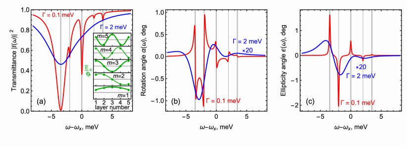
where the index enumerates the spatial modes and the index stands for the spin projection. Neglecting the phase factor, the functions are either even or odd with respect to the center of the stack. The eigen exciton modes in the stack of layers are sketched in the inset of Fig. 3a.
The modes are coupled to the electromagnetic field differently. The rates of exciton-photon interaction for the modes calculated after Eq. (16) have the form
| (23) |
and . It follows that the modes with odd are bright and, at , are characterized by the radiative decay rates
| (24) |
The radiative decay rates of excitons in the modes with even is much lower,
| (25) |
In the case of non-interacting modes, , the amplitude transmission coefficient of circularly polarized radiation through the stack is the sum of resonant contributions stemming from individual exciton modes
| (26) |
Using the definition Eq. (9) we obtain the expression for the rotation and ellipticity angles
| (27) |
where
| (28) | ||||
Figure 3 show the spectra of transmission, optical activity, and circular dichroism of the chiral stacks of layers. Red and blue curves correspond to the stacks with low and high non-radiative exciton decay rates . The transmission spectrum at low (red curve in Fig. 3a) features strong dips at the frequencies of the bright exciton modes (with odd ) and weak dips at the frequencies of the dark modes (with even ). The strengths of the resonances of both kind decrease with the increase of the mode index . At high , the resonances associated with individual exciton modes are widen and the fine structure of the transmission spectrum is not resolved.
The spectral dependences of the rotation angle (Fig. 3b) and the ellipticity angle (Fig. 3c) consist of 5 resonant contributions at the frequencies of eigen exciton modes . The resonances are well resolved in the case of low non-radiative exciton decay rate . The strengths of the resonances are determined by . As it is seen in Figs. 3b and 3c and also follows from Eq. (28), the resonances at the frequencies of bright and dark exciton modes are of comparable strengths and of opposite signs. Interestingly, the strongest resonance occurs at the frequency of the (dark) mode with . At high non-radiative decay rate (see blue curves in Figs. 3b and 3c), the resonances corresponding to the neighboring modes overlap and tend to cancel each other since .
III.3 Thick stacks
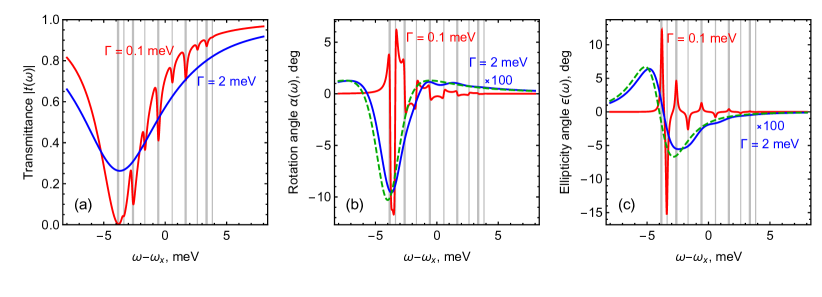
Figure 4 shows the spectra of transmission, optical activity, and circular dichroism for the chiral stack of layers. In stacks with large , the frequencies of eigen exciton modes, indicated by gray vertical lines in Fig. 4, fill the miniband from to . At large enough , the frequency separation between the neighboring modes becomes smaller than the broadening and the individual resonances are overlapped. The resulting angles of optical rotation and ellipticity are determined by the exciton modes with the frequencies close to the miniband bottom , see blue curves in Fig. 4c and 4d.
To describe the optical properties of a thick stack, we replace the set of Eqs. (II) for the exciton polarizations in individual layers with the differential equation for the continuous function
| (29) |
where is the Hamiltonian of excitons with the spin projection at the miniband bottom
| (30) |
, is the effective exciton mass, and is the amplitude of the electric field. The last term in the Hamiltonian (30) has the form of spin-orbit interaction linear in the exciton wave vector Shahnazaryan et al. (2015). It is the term originating from the chirality of the stack that gives rise to the optical activity. We also note that the continuous description above is valid provided , which is well fulfilled in realistic structures.
Equation (29) together with the Maxwell equation
| (31) |
form the closed set of differential equations for the functions and . These coupled equations describe the exciton-polaritons in the stack Agranovich and Ginzburg (2013); Ivchenko (2005).
The solution of Eqs. (29) and (31) in the bulk of the stack has the form with the dispersion given by
| (32) |
where is the exciton-polariton wave vector.
Neglecting the mass term in the exciton dispersion and considering the -linear spin-dependent term as a small correction we obtain
| (33) |
where
| (34) | |||
| (35) |
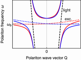
Figure 5 sketches the dispersions of exciton-polaritons with the spin projections along the wave vector (solid red and blue curves, respectively) given by Eq. (32) for a lossless structure. The exciton-polariton dispersion is formed as a result of the avoided crossing of the light dispersion (dashed black line) and the exciton dispersion (dashed red and blue curves). The exciton spin-orbit interaction described by the last term in the Hamiltonian (30) leads to the spin-orbit splitting of the polariton branches. The splitting is particularly strong for the lower polariton branch at high wave vectors, i.e., at the frequencies close to , where the original exciton splitting is strong and the exciton contribution to the polariton state is high. The spin-orbit splitting of polariton branches leads to a difference in the transmission coefficients for the right-handed and left-handed radiation.
To calculate the transmission coefficients we solve Eqs. (29) and (31) with the polariton dispersion (33) and the boundary conditions of the continuity of the functions and at the front and back surfaces of the stack. Since the major contribution to the rotation and ellipticity angles is proportional to the stack thickness, small possible spin-dependent corrections to the boundary conditions can be neglected. The calculation yields
| (36) |
where is the stack thickness.
Finally, for the rotation and ellipticity angles in thick chiral stacks we obtain
| (37) |
The rotation and ellipticity angles grow linearly with the stack thickness. The most pronounced conversion of the light polarization occurs for the light frequencies close to , where the polariton spin-orbit splitting is strongest, see Fig. 5. The dependences and calculated after Eq. (37) for the stack of 10 layers are shown in Figs. 4b and 4c, respectively, by green dashed curves. One can see that the analytical dependences agree well with the results of exact numerical calculations (blue curves). With the further increase of the number of layers or the non-radiative decay rate of excitons , the agreement becomes even better. An estimation after (37) yields rad/ and rad/ for stacks with low non-radiative decay rate meV and high non-radiative decay rate meV, respectively, and the other parameters meV Robert et al. (2016), meV, , and .
IV Polarized photoluminescence of chiral stacks
Finally, we discuss the photoluminescence (PL) of chiral stacks and show that the PL is circularly polarized. To calculate the PL spectrum, we apply the approach developed in Ref. Voronov et al., 2007 for multiple quantum well structures. This approach suggests that the PL is caused by random sources of excitons in the layers. The sources of exciton polarization in the layers are supposed to be identical and incoherent.
In this model, the exciton polarizations in the layers are described by Eq. (II) where the right-hand side is replaced with the rate of polarization generation in the layer ,
| (38) |
The exciton generations in the layers are independent, therefore, the correlation function has the form .
The amplitude of the electric field of the radiation emitted by the stack in the direction is given by Eq. (6) with . This yields the expression for the spectral density of the emitted radiation
| (39) |
and .
Following the procedure described in the previous section we calculate the exciton polarizations (38) in the layers and then the PL spectrum (39). Particularly, in the case of non-interacting exciton modes in the multi-layer structure, the spectral density of the PL with the certain circular polarization assumes the form
| (40) |
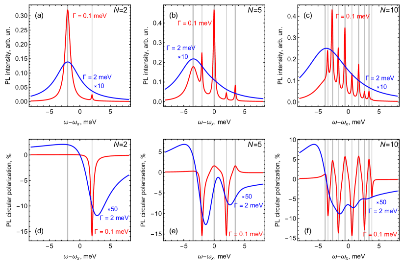
Figures 6a-6c show the total PL spectra of chiral stacks consisting of , 5, and 10 monolayers. The spectra are calculated following Eqs. (38) and (39) for the frequency-independent which corresponds to the pumping of different exciton states with the equal probability. Similarly to the spectra of transmission (Figs. 2a, 3a, and 4a), the PL spectra in the stacks with low non-radiative decay rate comprise peaks associated with the eigen exciton modes. The peaks at the frequencies of bright exciton modes (indicated by thick vertical lines) are stronger than the peaks at the frequencies of dark exciton modes (indicated by thin vertical lines). In the stacks with high non-radiative decay rate the individual peaks are broadened forming the smooth PL spectra.
Figures 6d-6f show the spectral dependence of the PL circular polarization degree defined by
| (41) |
The PL is circularly polarized because of the chiral stacking of the layers. In structures with low non-radiative decay rate (red curves), the degree of circular polarization at the frequencies of dark exciton modes is much higher than that at the frequencies of bright modes. The reason is that of the radiation emitted by the -th exciton mode is determined by the ratio , as follows from Eqs. (40) and (41). While is of the same order for bright and dark modes [Eq. (28)], much smaller value of for dark modes than for bright modes [Eqs. (24) and (25)] leads to the higher degree of circular polarization. In stacks with high (blue curves), the contributions of individual exciton modes overlap and partly compensate each other leading to the decrease of the PL circular polarization degree.
V Summary
To summarize, we have developed a microscopic theory of optical activity and circular dichroism in chiral stacks of two-dimensional crystals, such as the layers of transition metal dichalcogenides, in the spectral range of exciton transitions. The theory takes into account spin-dependent transport of excitons between the layers of the stack and coupling of excitons to an electromagnetic field. We have shown that the frequency dependence of the optical rotation angle and the ellipticity angle exhibits complex behavior reflecting the structure of eigen exciton modes in chiral stacks. In stacks with low non-radiative decay rate of excitons, the spectra of optical activity and circular dichroism comprise sharp resonances associated with individual exciton modes. In stacks with high non-radiative decay rate, the individual resonances overlap and partially compensate each other. The spectra of optical activity and circular dichroism in thick chiral stacks is well described by the developed analytical theory of exciton-polaritons with the effective spin-orbit coupling. We have also calculated the spectra of exciton photoluminescence of chiral stacks in the conditions of non-resonant pumping and shown that the photoluminescence is circularly polarized.
Acknowledgments
We acknowledge fruitful discussions with A.N. Poddubny, E.L. Ivchenko, and L.E. Golub. This work was supported by the Government of the Russian Federation (Project No. 14.W03.31.0011 at the Ioffe Institute). A.V.P. also acknowledges the support from the RF president grant SP-2912.2016.5 and the “Basis” Foundation.
References
- Goldstein (2011) D. H. Goldstein, Polarized Light, Third Edition (Taylor and Francis Group, 2011).
- Kaminsky (2000) W. Kaminsky, “Experimental and phenomenological aspects of circular birefringence and related properties in transparent crystals,” Rep. Prog. Phys. 63, 1575 (2000).
- Bose (1898) J. C. Bose, “On the rotation of plane of polarisation of electric waves by a twisted structure,” Proc. R. Soc. Lond. 63, 146–152 (1898).
- Wang et al. (2017) J. Wang, Z. Shen, and W. Wu, “Broadband and high-efficiency circular polarizer based on planar-helix chiral metamaterials,” Appl. Phys. Lett. 111, 113503 (2017).
- Chadha et al. (2014) A. S. Chadha, D. Zhao, and W. Zhou, “Comparative study of metallic and dielectric helix photonic metamaterial,” Opt. Mater. Express 4, 2460–2467 (2014).
- Bennett et al. (1992) C. H. Bennett, F. Bessette, G. Brassard, L. Salvail, and J. Smolin, “Experimental quantum cryptography,” J. Cryptol. 5, 3–28 (1992).
- Kizel’ et al. (1975) V. A. Kizel’, Yu. I. Krasilov, and V. I. Burkov, “Experimental studies of gyrotropy of crystals,” Sov. Phys. Usp. 18, 745–773 (1975).
- Mason (1982) S. F. Mason, Molecular Optical Activity and the Chiral Discriminations (Cambridge University Press, 1982).
- Nomura (1960) K. C. Nomura, “Optical activity in tellurium,” Phys. Rev. Lett. 5, 500–501 (1960).
- Hobden (1967) M. V. Hobden, “Optical activity in a non-enantiomorphous crystal silver gallium sulphide,” Nature 216, 678–678 (1967).
- Agranovich and Ginzburg (2013) V. M. Agranovich and V. Ginzburg, Crystal Optics with Spatial Dispersion, and Excitons (Springer Series in Solid-State Sciences) (Springer, 2013).
- lvchenko and Sel’kin (1979) E. L. lvchenko and A. V. Sel’kin, “Natural optical activity in semiconductors with wurtzite structure,” Sov. Phys. JETP 49, 933–942 (1979).
- Kotova et al. (2016) L. V. Kotova, A. V. Platonov, V. N. Kats, V. P. Kochereshko, S. V. Sorokin, S. V. Ivanov, and L. E. Golub, “Optical activity of quantum wells,” Phys. Rev. B 94, 165309 (2016).
- Rogacheva et al. (2006) A. V. Rogacheva, V. A. Fedotov, A. S. Schwanecke, and N. I. Zheludev, “Giant gyrotropy due to electromagnetic-field coupling in a bilayered chiral structure,” Phys. Rev. Lett. 97, 177401 (2006).
- Lobanov et al. (2015) S. V. Lobanov, T. Weiss, N. A. Gippius, S. G. Tikhodeev, V. D. Kulakovskii, K. Konishi, and M. Kuwata-Gonokami, “Polarization control of quantum dot emission by chiral photonic crystal slabs,” Opt. Lett. 40, 1528–1531 (2015).
- Demenev et al. (2016) A. A. Demenev, V. D. Kulakovskii, C. Schneider, S. Brodbeck, M. Kamp, S. Höfling, S. V. Lobanov, T. Weiss, N. A. Gippius, and S. G. Tikhodeev, “Circularly polarized lasing in chiral modulated semiconductor microcavity with GaAs quantum wells,” Appl. Phys. Lett. 109, 171106 (2016).
- Mamonov et al. (2014) E. A. Mamonov, I. A. Kolmychek, S. Vandendriessche, M. Hojeij, Y. Ekinci, V. K. Valev, T. Verbiest, and T. V. Murzina, “Anisotropy versus circular dichroism in second harmonic generation from fourfold symmetric arrays of g-shaped nanostructures,” Phys. Rev. B 89, 121113 (2014).
- Plum et al. (2009) E. Plum, X.-X. Liu, V. A. Fedotov, Y. Chen, D. P. Tsai, and N. I. Zheludev, “Metamaterials: Optical activity without chirality,” Phys. Rev. Lett. 102, 113902 (2009).
- Minovich et al. (2015) A. E. Minovich, A. E. Miroshnichenko, A. Y. Bykov, T. V. Murzina, D. N. Neshev, and Y. S. Kivshar, “Functional and nonlinear optical metasurfaces,” Laser. Photon. Rev. 9, 195–213 (2015).
- Collins et al. (2017) J. T. Collins, C. Kuppe, D. C. Hooper, C. Sibilia, M. Centini, and V. K. Valev, “Chirality and chiroptical effects in metal nanostructures: Fundamentals and current trends,” Adv. Opt. Mater. 5, 1700182 (2017).
- Geim and Grigorieva (2013) A. K. Geim and I. V. Grigorieva, “Van der waals heterostructures,” Nature 499, 419 (2013).
- Lotsch (2015) B. V. Lotsch, “Vertical 2D heterostructures,” Annu. Rev. Mater. Res. 45, 85–109 (2015).
- Kim et al. (2016) C.-J. Kim, A. Sánchez-Castillo, Z. Ziegler, Y. Ogawa, C. Noguez, and J. Park, “Chiral atomically thin films,” Nat. Nanotechnol. 11, 520 (2016).
- Mak et al. (2010) K. F. Mak, C. Lee, J. Hone, J. Shan, and T. F. Heinz, “Atomically thin MoS2: A new direct-gap semiconductor,” Phys. Rev. Lett. 105, 136805 (2010).
- Mak and Shan (2016) K. F. Mak and J. Shan, “Photonics and optoelectronics of 2D semiconductor transition metal dichalcogenides,” Nat. Photon. 10, 216–226 (2016).
- Cadiz et al. (2017) F. Cadiz, E. Courtade, C. Robert, G. Wang, Y. Shen, H. Cai, T. Taniguchi, K. Watanabe, H. Carrere, D. Lagarde, M. Manca, T. Amand, P. Renucci, S. Tongay, X. Marie, and B. Urbaszek, “Excitonic linewidth approaching the homogeneous limit in MoS2-based van der waals heterostructures,” Phys. Rev. X 7, 021026 (2017).
- Jun et al. (2017) X. Jun, Z. Mervin, W. Yuan, and Z. Xiang, “Excitons in atomically thin 2D semiconductors and their applications,” Nanophotonics 6, 1309 (2017).
- Arora et al. (2015) A. Arora, M. Koperski, K. Nogajewski, J. Marcus, C. Faugeras, and M. Potemski, “Excitonic resonances in thin films of WSe2: from monolayer to bulk material,” Nanoscale 7, 10421–10429 (2015).
- Koperski et al. (2017) M. Koperski, M.R. Molas, A. Arora, K. Nogajewski, A. O. Slobodeniuk, C. Faugeras, and M. Potemski, “Optical properties of atomically thin transition metal dichalcogenides: observations and puzzles,” Nanophotonics 6, 1289 (2017).
- Liu et al. (2014) K. Liu, L. Zhang, T. Cao, C. Jin, D. Qiu, Q. Zhou, A. Zettl, P. Yang, S. G. Louie, and F. Wang, “Evolution of interlayer coupling in twisted molybdenum disulfide bilayers,” Nat. Commun. 5, 4966 (2014).
- Huang et al. (2014) S. Huang, X. Ling, L. Liang, J. Kong, H. Terrones, V. Meunier, and M. S. Dresselhaus, “Probing the interlayer coupling of twisted bilayer MoS2 using photoluminescence spectroscopy,” Nano Lett. 14, 5500–5508 (2014).
- van der Zande et al. (2014) A. M. van der Zande, J. Kunstmann, A. Chernikov, D. A. Chenet, Y. You, X. Zhang, P. Y. Huang, T. C. Berkelbach, L. Wang, F. Zhang, M. S. Hybertsen, D. A. Muller, D. R. Reichman, T. F. Heinz, and J. C. Hone, “Tailoring the electronic structure in bilayer molybdenum disulfide via interlayer twist,” Nano Lett. 14, 3869–3875 (2014).
- Yan et al. (2015) J. Yan, J. Xia, X. Wang, L. Liu, J.-L. Kuo, B. K. Tay, S. Chen, W. Zhou, Z. Liu, and Z. X. Shen, “Stacking-dependent interlayer coupling in trilayer MoS2 with broken inversion symmetry,” Nano Lett. 15, 8155–8161 (2015).
- Plechinger et al. (2015) G. Plechinger, F. Mooshammer, A. Castellanos-Gomez, G. A. Steele, C. Schüller, and T. Korn, “Optical spectroscopy of interlayer coupling in artificially stacked MoS2 layers,” 2D Materials 2, 034016 (2015).
- Xia et al. (2017) J. Xia, J. Yan, and Z. X. Shen, “Transition metal dichalcogenides: structural, optical and electronic property tuning via thickness and stacking,” FlatChem. 4, 1 – 19 (2017).
- Arora et al. (2017) A. Arora, M. Drüppel, R. Schmidt, T. Deilmann, R. Schneider, M. R. Molas, P. Marauhn, S. Michaelis de Vasconcellos, M. Potemski, M. Rohlfing, and R. Bratschitsch, “Interlayer excitons in a bulk van der waals semiconductor,” Nat. Commun. 8, 639 (2017).
- Nagler et al. (2017) P. Nagler, G. Plechinger, M. V. Ballottin, A. Mitioglu, S. Meier, N. Paradiso, C. Strunk, A. Chernikov, P. C. M. Christianen, C. Schüller, and T. Korn, “Interlayer exciton dynamics in a dichalcogenide monolayer heterostructure,” 2D Materials 4, 025112 (2017).
- Robert et al. (2016) C. Robert, D. Lagarde, F. Cadiz, G. Wang, B. Lassagne, T. Amand, A. Balocchi, P. Renucci, S. Tongay, B. Urbaszek, and X. Marie, “Exciton radiative lifetime in transition metal dichalcogenide monolayers,” Phys. Rev. B 93, 205423 (2016).
- Ivchenko (2005) E. L. Ivchenko, Optical Spectroscopy of Semiconductor Nanostructures (Alpha Science International, Harrow, UK, 2005).
- Ivchenko et al. (1994) E.L. Ivchenko, A. I. Nesvizhskii, and S. Jorda, “Bragg reflection of light from quantum-well structures,” Phys. Solid State 36, 1156 (1994).
- Poshakinskiy et al. (2012) A. V. Poshakinskiy, A. N. Poddubny, and S. A. Tarasenko, “Reflection of short polarized optical pulses from periodic and aperiodic multiple quantum well structures,” Phys. Rev. B 86, 205304 (2012).
- Kazanov et al. (2017) D.R. Kazanov, A.V. Poshakinskiy, and T.V. Shubina, “Resonant photonic crystals based on van der waals heterostructures for effective light pulse retardation,” Superlattices Microstruct. 112, 639 – 643 (2017).
- Note (1) The eigen exciton modes are strictly symmetric or antisymmetric only at .
- Shahnazaryan et al. (2015) V. Shahnazaryan, S. Morina, S. A. Tarasenko, and I. A. Shelykh, “Spin currents of exciton polaritons in microcavities with (110)-oriented quantum wells,” Phys. Rev. B 92, 155305 (2015).
- Voronov et al. (2007) M.M. Voronov, E.L. Ivchenko, M.V. Erementchouk, L.I. Deych, and A.A. Lisyansky, “Photoluminescence spectroscopy of one-dimensional resonant photonic crystals,” J. Lumin. 125, 112–117 (2007).