Electromagnetically induced transparency in an isotopically purified Nd3+:YLiF4 crystal
Abstract
We report the first observation of electromagnetically induced transparency (EIT) in an isotopically purified Nd3+:YLiF4 crystal. This crystal demonstrates inhomogeneous broadening of optical transitions of about 35 MHz. EIT is observed in a symmetrical -like system formed by two hyperfine sublevels of the ground state corresponding to a zero first order Zeeman (ZEFOZ) transition and a hyperfine sublevel of the excited state, which is not coupled to other ground-state sublevels. It is found that transmission of the probe field as a function of the two-photon detuning demonstrates a comb-like structure that can be attributed to superhyperfine coupling between Nd3+ ions and fluorine nuclei. The observed structure can be resolved only in the vicinity of the ZEFOZ point where the homogeneous linewidth of the spin transition is sufficiently small. The results pave the way for implementing solid-state quantum memories based on off-resonant Raman interaction without spectral tailoring of optical transitions.
Electromagnetically induced transparency (EIT) is a quantum interference effect which can be observed in a multilevel atomic system where resonant absorption is suppressed and a narrow transparency window is created via coherent interaction with a strong coupling field Harris1997 ; Fleischhauer2005 . Appearance of the transparency window is accompanied by strong dispersion and enhanced nonlinearity, which has led to a variety of applications including slow light propagation Hau1999 ; Budker1999 , optical storage Phillips2001 , precision measurements Budker2002 ; Acosta2013 , amplification and lasing without inversion Zibrov1995 , etc. In particular, EIT is a promising approach to creating optical quantum memory Fleischhauer2000 , which is a basic component required for scalable quantum computing and long-distance quantum communication Lvovsky2009 ; Bussieres2013 ; Heshami2016 . In this respect, it is important to study EIT in materials promising for quantum storage. Among them, rare-earth-ion doped crystals at low temperature have been one of the best candidates Thiel2011 since they provide long coherence times both on optical and spin transitions, high optical density, no atomic diffusion, possibility of controlling resonant frequencies and atomic interactions by external electric and magnetic fields, etc. In particular, EIT has been extensively studied in the crystals doped by praseodymium ions Ham1997 ; Ichimura1998 ; Turukhin2002 ; Longdell2005 ; Goldner2009 ; Akhmedzhanov2006 ; Heinze2013 ; Schraft2016 , and up to now the largest EIT storage time ( min) and efficiency (%) have been demonstrated in the Pr3+:Y2SiO5 crystal Heinze2013 ; Schraft2016 . EIT was also reported at the telecom wavelength around 1.5 m in the same host material doped by erbium ions Baldit2010 .
In this work, we present experimental results demonstrating EIT in an isotopically purified Nd3+:YLiF4 crystal. Neodymium doped crystals are among promising materials for quantum memory applications since they demonstrate allowed transitions at the wavelength around 850 nm, which corresponds to transparency windows both in optical fibres and atmosphere. In addition, this wavelength is accessible for modern diode lasers and convenient for single photon detection. Odd neodymium isotopes demonstrate hyperfine structures with overall splitting in the GHz range, which is promising for storing broadband photons and microwave photons. They have long spin coherence times reaching 9 ms at cryogenic temperatures Wolfowicz2015 . On the other hand, it has long been known that erbium and neodymium ions doped into isotopically purified YLiF4 crystals, where only the 7Li isotope is present, demonstrate very narrow optical transitions ( MHz) Macfarlane1992 ; Macfarlane1998 . Such small inhomogeneous broadening proves to be very attractive for implementing off-resonant Raman quantum memory protocols Moiseev2011 ; Moiseev2013 ; Zhang2013 ; Kalachev2013 ; Zhang2014 , which has recently made these crystals a subject of active research Zhou2013 ; Marino2016 ; Akhmedzhanov2016 ; Gerasimov2016 ; Kukharchyk2017 . Since hyperfine structure of the optical transition is clearly resolved in the present material, observing EIT needs no special ensemble preparation such as spectral tailoring with anti-hole creating and optical pumping. Moreover, even superhyperfine structure can be resolved in the EIT process, which opens way for optical addressing nuclear spin states of surrounding ions and for quantum storage on the superhyperfine states as well.
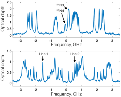
Our experiments were carried out using the Y7LiF4 crystal (99.7% 7Li) containing 0.005 at.% of 143Nd3+ impurities (96.5% 143Nd). The same material was used in Akhmedzhanov2016 ; Akhmedzhanov2016b for implementing quantum memory protocols based on atomic frequency combs. The crystal was grown by using Bridgman-Stockbarger method in an argon atmosphere of high purity (see Akhmedzhanov2016 ; Kukharchyk2017 for details). We started by measuring the absorption spectrum ( polarization) of the sample on the 4I–4F transition (867.5 nm) at 2 K as a function of dc magnetic field directed along the crystal axis. Two examples are shown in Fig. 1. The isotope 143Nd has a nuclear spin of , while the doubly degenerate electronic states are described by the effective electron spin . The hyperfine structure of the ground and excited states is described by the effective spin Hamiltonian
| (1) |
where MHz/mT is the Bohr magneton, and are the components of the factor parallel and perpendicular to the axis, are the components of the external magnetic field, and are the electron- and nuclear-spin operators, respectively, and are the hyperfine parameters, and is the quadrupole constant. The ground state parameters are known from electron paramagnetic resonance (EPR) measurements Sattler1971 (see also Macfarlane1998 ): MHz, MHz, and . The excited state parameters can be determined from the measured optical spectra as was done in Macfarlane1998 , which is posssible due to small inhomogeneous broadening of the optical transition. In the present work, the resulting parameters for the excited state are determined to be MHz, MHz, and , which are close to the values obtained in Macfarlane1998 . In both cases, the quadrupole constant is found to be negligibly small.
Considering the ground electronic state, for certain values of the external magnetic field it is expected to observe hyperfine transitions which are insensitive to the magnetic field fluctuations. Such zero first order Zeeman (ZEFOZ) transitions Fraval2004 ; Lovric2011 ; McAuslan2012 can demonstrate extremely long spin coherence times Zong2015 thereby providing the optimal conditions for quantum storage. The calculations show that the most interesting ZEFOZ transition appears under application of the longitudinal magnetic field of about 63.6 mT. In this case, the hyperfine sublevels of the ground state form an ideal symmetric -scheme with a hyperfine sublevel of the excited state. To be more precise, under such a magnetic field we have the following states:
| (2) | ||||
| (3) | ||||
| (4) |
where and correspond to th sublevel of the ground () and excited () state, respectively, while stands for the eigenstate of the Hamiltonian (Electromagnetically induced transparency in an isotopically purified Nd3+:YLiF4 crystal) with specific values of the axial component of the nuclear spin () and of the effective electron spin (). The excited state sublevel is coupled only to the pair of the ground state sublevels, and , by equally strong optical transitions with polarization (Fig. 2). The resulting most efficient and symmetric -scheme is very convenient for observing Raman interaction between the atoms and two optical fields. In particular, numerics show that it provides a large signal-to-noise ratio when single photon states are stored and reconstructed via off-resonant Raman scattering Berezhnoi2017 . It is worth noting that in the external magnetic field the inhomogeneous broadening of the optical transitions involved is reduced to MHz compared to MHz observed in the zero field case.
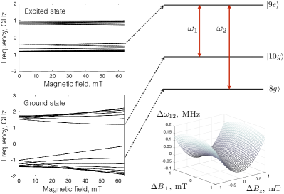
The frequency of the hyperfine transition as a function of magnetic field around the ZEFOZ point is described by the formula
| (5) |
where MHz is the ZEFOZ transition frequency, is the deviation of magnetic field from the ZEFOZ point, and are the curvatures which are calculated to be kHz/mT2 and kHz/mT2. The opposite signs of the second derivatives correspond to a saddle-type dependence (Fig. 2). At the same time, the frequencies and are linearly proportional to the magnetic field with the gradient MHz/mT.
The experimental setup for studying electromagnetically induced transparency is shown in Fig. 3. The emission of a single mode Ti:Sa laser (0.5 W power, 500 kHz linewidth) is split into two separate beams using a polarizing beam splitter. One of the beams is used as pump, the other as probe. The relative intensities of the two beams can be adjusted using a halfwave plate placed in front of the beam splitter. In order to implement the required pulse sequences and frequency scans, each beam is then passed through an acousto optic modulator (AOM). The pump beam AOM (AOM2) is set up in a single pass scheme while the probe AOM (AOM1) is set up in the double pass scheme to avoid the beam walk during the frequency scan. The probe beam is then passed through an electro optic modulator (EOM) to create the required frequency detuning from the coupling beam. The two beams are then combined on the beam splitter and focused onto the crystal of 8 mm length that is placed inside a superconducting solenoid. The crystal and the solenoid are kept at 2 K inside a liquid helium cryostat. Both laser fields propagate along the optical -axis and are polarized perpendicular to it ( polarization). After the cryostat the coupling field is cut off using a polarizer (a Glan prism), while the probe field is then sent into a tunable confocal Fabry-Perot cavity for additional frequency filtering. One of the mirrors is mounted onto a piezoceramic element so that the cavity length can be controlled by external voltage. The free spectral range of the cavity was 9.4 GHz with the finesse of 11.
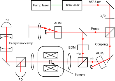
The described setup is meant to accomplish two tasks. The first is to control how well the coupling and probe beams spatially overlap. This is done by using the coupling beam to burn a long lived spectral hole in the inhomogeneously broadened line which is then read out using the scanned probe beam. The beams are adjusted until the depth of this hole is maximized. For this experiment, the EOM is turned off while the AOM frequencies are tuned so that the central frequencies of the two beams are the same. The second task is to select the appropriate frequency sideband of the probe beam that is modulated by the EOM. This is done by measuring the absorption spectra for different sidebands. Initially, the EOM is turned off and the laser is tuned to the transition (Line 1 in Fig. 1). Then, the EOM is turned on and the frequency is scanned around the expected ZEFOZ transition frequency. We select one of the sidebands using the Fabry-Perot cavity and measure the absorption profile. For the correct sideband, the observed profile corresponds to the part of the spectrum around the transition (Line 2 in Fig. 1). For the wrong sideband, no absorption is observed. In addition, the interferometer also filters out the part of the coupling beam that is not cut off by the polarizer. In experiments the coupling field is tuned to the transition (Line 1) while the probe field is tuned either to the same transition for the hole burning measurements or to the transition (Line 2) for studying the electromagnetically induced transparency.
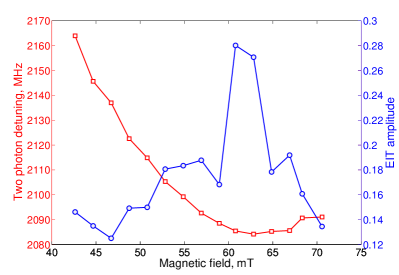
EIT can be observed by comparing the intensities of the probe pulse with and without the coupling field present. When the two-photon resonance condition is satisfied, the coupling field makes the crystal more transparent for the probe pulse. The effect is described by the EIT amplitude which is defined as the ratio , where () is the resonant absorption coefficient with the coupling field tuned on (off). The experiment is performed for different values of the external magnetic field. The resulting values of the EIT amplitude and EIT resonance positions (the values of the two-photon transition frequency) are shown in Fig. 4. It can be seen that the highest transparency coincides with the location of the ZEFOZ point (the point where the two-photon transition frequency attains minimum as a function of the longitudinal field ). The dependence of on the magnetic field is in good agreement with the difference between the and sublevels calculated from the Hamiltonian (Electromagnetically induced transparency in an isotopically purified Nd3+:YLiF4 crystal).
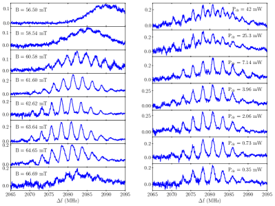
It is worth noting that the total width of the EIT feature is around 12 MHz and it does not depend on the pump intensity or the value of the external magnetic field. However, under certain conditions the internal structure of the transparency window changes. For instance, when the external magnetic field is set to the value corresponding to the ZEFOZ point, it can be seen that the EIT feature is composed of nine peaks. The peaks are separated by about 2.8 MHz and each peak is around 1 MHz wide. When the magnetic field is detuned from the ZEFOZ point, the width of each peak increases while the distance between the peaks remains the same (Fig. 5, left). As a result, about 7 mT away from the ZEFOZ point the peaks completely overlap, forming a single 12 MHz wide EIT feature without any resolvable internal structure. In addition, an interesting effect can be observed when the pump intensity is increased (see Fig. 5, right). The resulting high pump intensities cause additional peaks to appear in the EIT feature. These peaks are located exactly between the peaks that can be observed at lower intensities.
We believe that the splitting of the EIT feature at low coupling field intensities is caused by superhyperfine interaction between the Nd3+ electronic spins and the neighbouring fluorine nuclear spins. Superhyperfine structure in Nd doped YLiF crystals has been previously studied using EPR in external magnetic fields both parallel and perpendicular to the crystal -axis Aminov2015 . Similarly to this work, we observe nine separate components in the EIT feature, and the splitting between the peaks is approximately equal to the nuclear Zeeman energy of the fluorine ions (2.5 MHz for the field around 63 mT). The picture is quite similar to what is expected in the case when the superhyperfine interaction is smaller than the Zeeman energy Aminov2013 . The latter is reasonable because the expectation value of the neodymium magnetic moment in the states and is equal to zero. It is worth noting that the hole burned on the transition shows a similar but much less pronounced comb-like structure, which is most likely caused by the superhyperfine splitting of the excited sublevel (cf. Akhmedzhanov2016 ).
While the present experiment demonstrates the power of EIT as a spectroscopy method, the existence of the superhyperfine structure made it impossible to obtain transparencies close to 100%. High EIT transmission could be achieved by preparing the atomic ensemble in one of the superhyperfine states, which corresponds to polarizing fluorine nuclear spins. It has long been known that the YLiF4 matrix is quite promising for the dynamic polarization of 7Li and 19F nuclei Antipin1978 so that higher EIT transmission seems feasible.
The blurring of the comb-like EIT structure with detuning of the magnetic field from the ZEFOZ point can be explained by increasing homogeneous broadening of the two-photon transition due to the magnetic noise. To estimate this effect, we take advantage of a simple model developed in Lovric2011 and consider Gaussian magnetic noise, which allows us to write the linewidth as
| (6) |
where is the amplitude (variance) of the magnetic field fluctuations created by surrounding spins, is the detuning of the external magnetic field from the ZEFOZ point, and is the broadening due to other effects including non-resolved overlapping of superhyperfine lines (see Aminov2013 for more details). Then the dependence shown in Fig. 5, left is simulated quite well with the curvature values calculated above, MHz and mT. The latter value proves to be close the local magnetic field estimation obtained in Macfarlane1998 . On the other hand, such a line broadening should be accompanied by the decrease of the EIT amplitude, which indeed has been clearly observed in our experiment (Fig. 4).
To sum up, in this work we observe electromagnetically induced transparency in an isotopically pure 143Nd3+:Y7LiF4 crystal demonstrating narrow optical transitions. We find that when the crystal is placed into an appropriate external magnetic field corresponding to the ZEFOZ point, we can resolve narrow peaks in the EIT profile. We believe that these peaks are caused by the superhyperfine splitting of the Nd3+ hyperfine levels in the ground electronic state. Thus, our results demonstrate that the crystal is potentially attractive for implementing Raman schemes of quantum memory involving not only hyperfine but also superhyperfine states without spectral tailoring of optical transitions.
The authors thank S.L. Korableva for the crystal growth and Pavel Bushev for useful comments and discussions. The work was supported by the Russian Science Foundation, Grant No. 14-12-00806.
References
- (1) S. E. Harris, Physics Today 50(7), 36 (1997).
- (2) M. Fleischhauer, A. Imamoglu, and J. P. Marangos, Rev. Mod. Phys. 77, 633 (2005).
- (3) L. V. Hau, S. E. Harris, Z. Dutton, and C. H. Behroozi, Nature 397, 594 (1999).
- (4) D. Budker, D. F. Kimball, S. M. Rochester, and V. V. Yashchuk, Phys. Rev. Lett. 83, 1767 (1999).
- (5) D. F. Phillips, A. Fleischhauer, A. Mair, R. L. Walsworth, and M. D. Lukin, Phys. Rev. Lett. 86, 783 (2001).
- (6) D. Budker, W. Gawlik, D. F. Kimball, S. M. Rochester, V. V. Yashchuk, and A. Weis, Rev. Mod. Phys. 74, 1153 (2002).
- (7) V. M. Acosta, K. Jensen, C. Santori, D. Budker, and R. G. Beausoleil, Phys. Rev. Lett. 110, 213605 (2013).
- (8) A. S. Zibrov, M. D. Lukin, D. E. Nikonov, L. Hollberg, M. O. Scully , V. L. Velichansky, and H. G. Robinson, Phys. Rev. Lett. 75, 1499 (1995).
- (9) M. Fleischhauer, and M. D. Lukin, Phys. Rev. Lett. 84, 5094 (2000).
- (10) A. I. Lvovsky, B. C. Sanders, and W. Tittel, Nature Photonics 3, 706 (2009).
- (11) F. Bussieres, N. Sangouard, M. Afzelius, H. de Riedmatten, C. Simon, and W. Tittel, Journal of Modern Optics 60, 1519 (2013).
- (12) K. Heshami, D. G. England, P. C. Humphreys, P. J. Bustard, V. M. Acosta, J. Nunn, and B. J. Sussman, Journal of Modern Optics 63, 2005 (2016).
- (13) C. W. Thiel, T. Bottger, and R. L. Cone, Journal of Luminescence 131, 353 (2011).
- (14) B. S. Ham, M. S. Shahriar, and P. R. Hemmer, Opt. Lett. 22. 1138 (1997).
- (15) K. Ichimura, K. Yamamoto, and N. Gemma, Phys. Rev. A 58, 4116 (1998).
- (16) A. V. Turukhin, V. S. Sudarshanam, M. S. Shahriar, J. A. Musser, B. S. Ham, and P. R. Hemmer, Phys. Rev. Lett. 88, 023602 (2001).
- (17) J. J. Longdell, E. Fraval, M. J. Sellars, and N. B. Manson, Phys. Rev. Lett. 95, 063601 (2005).
- (18) R. Akhmedzhanov, L. Gushin, E. Kuznetsova, A. Litvak, V. Yasenkov, and N. Zharova, J. Mod. Opt. 53, 2449 (2006).
- (19) P. Goldner, O. Guillot-Noel, F. Beaudoux, Y. Le Du, J. Lejay, T. Chaneliere, J.-L. Le Gouet, L. Rippe, A. Amari, A. Walther, and S. Kroll, Phys. Rev. A 79, 033809 (2009).
- (20) G. Heinze, C. Hubrich, and T. Halfmann, Phys. Rev. Lett. 111, 033601 (2013).
- (21) D. Schraft, M. Hain, N. Lorenz, and T. Halfmann, Phys. Rev. Lett. 116, 073602 (2016).
- (22) E. Baldit, K. Bencheikh, P. Monnier, S. Briaudeau, J. A. Levenson, V. Crozatier, I. Lorgere, F. Bretenaker, J.-L. Le Gouet, O. Guillot-Noel, and P. Goldner, Phys. Rev. B 81, 144303 (2010).
- (23) G. Wolfowicz, H. Maier-Flaig, R. Marino, A. Ferrier, H. Vezin, J. J. L. Morton, and P. Goldner, Phys. Rev. Lett. 114, 170503 (2015).
- (24) R. M. Macfarlane, A. Cassanho, and R. S. Meltzer, Phys. Rev. Lett. 69, 542 (1992).
- (25) R. M. Macfarlane, R. S. Meltzer, and B. Z. Malkin, Phys. Rev. B 58, 5692 (1998).
- (26) S. A. Moiseev, and W. Tittel, New J. Phys. 13, 063035 (2011).
- (27) S. A. Moiseev, Phys. Rev. A 88, 012304 (2013).
- (28) X. Zhang, A. Kalachev, and O. Kocharovskaya, Phys. Rev. A 87, 013811 (2013).
- (29) A. Kalachev, and O. Kocharovskaya, Phys. Rev. A 88, 033846 (2013).
- (30) X. Zhang, A. Kalachev, and O. Kocharovskaya, Phys. Rev. A 90, 052322 (2014).
- (31) Z.-Q. Zhou, J. Wang, C.-F. Li, and G.-C. Guo, Scientific Reports 3, 2754 (2013).
- (32) R. Marino, I. Lorgere, O. Guillot-Noel, H. Vezin, A. Toncelli, M. Tonelli, J.-L. Le Gouet, and P. Goldner, Journal of Luminescence 169, 478 (2016).
- (33) R. A. Akhmedzhanov, L. A. Gushchin, A. A. Kalachev, S. L. Korableva, D. A. Sobgayda, and I. V. Zelensky, Laser Phys. Lett. 13, 015202 (2016).
- (34) K. I. Gerasimov, M. M. Minnegaliev, B. Z. Malkin, E. I. Baibekov, and S. A. Moiseev, Phys. Rev. B 94, 054429 (2016).
- (35) N. Kukharchyk, D. Sholokhov, S. Korableva, A. Kalachev, and P. Bushev, New J. Phys. 20, 023044 (2018).
- (36) R. A. Akhmedzhanov, L. A. Gushchin, A. A. Kalachev, N. A. Nizov, V. A. Nizov, D. A. Sobgayda, and I. V. Zelensky, Laser Phys. Lett. 13, 115203 (2016).
- (37) J. P. Sattler, and J. Nemarich, Phys. Rev. B 4, 1 (1971).
- (38) E. Fraval, M. J. Sellars, and J. J. Longdell, Phys. Rev. Lett. 92, 077601 (2004).
- (39) M. Lovrić, P. Glasenapp, D. Suter, B. Tumino, A. Ferrier, P. Goldner, M. Sabooni, L. Rippe, and S. Kröll, Phys. Rev. B 84, 104417 (2011).
- (40) D. L. McAuslan, J. G. Bartholomew, M. J. Sellars, and J. J. Longdell, Phys. Rev. A 85, 032339 (2012).
- (41) M. Zhong, M. P. Hedges, R. L. Ahlefeldt, J. G. Bartholomew, S. E. Beavan, S. M. Wittig, J. J. Longdell, and M. J. Sellars, Nature 517, 177 (2015).
- (42) A. D. Berezhnoi, and A.A. Kalachev, Quantum Electronics 47, 790 (2017).
- (43) L. K. Aminov, M. R. Gafurov, S. L. Korableva, I. N. Kurkin, and A. A. Rodionov, Phys. Solid State 57, 2400 (2015).
- (44) L. K. Aminov, I. N. Kurkin, and B. Z. Malkin, Phys. Solid State 55, 1343 (2013).
- (45) A. A. Antipin, B. N. Kazakov, S. L. Korableva, R. M. Rakhmatullin, Yu. K. Chirkin, and A. A. Fedii, Soviet Physics Journal 21, 1187 (1978).