Optimizing TCP Goodput and Delay in next generation IEEE 802.11 (ax) devices
Abstract
In this paper we suggest three scheduling strategies for the IEEE 802.11ax transmission of DL unidirectional TCP data from the Access Point to stations. Two strategies are based on the Single User operation mode and one is based on the Multi User operation mode, using Multi User Multiple-Input-Multiple-Output (MU-MIMO) and OFDMA. We measure the Goodput of the system as a function of the time intervals over which these Goodputs are received in all three strategies. For up to 8 stations the MU strategy outperforms the SU. For 16 and 32 stations it is not clear whether MU outperforms SU or vice versa. For 64 stations the SU strategies outperform the MU significantly. We also checked the influence of the Delayed Acks feature on the received Goodputs and found that this feature has significance only when the TCP data segments are relatively short.
Keywords: 802.11ax; TCP; Aggregation; Reverse Direction; Transmission Opportunity; Goodput; MIMO; Multi User; OFDMA;
1 Introduction
1.1 Background
The latest IEEE 802.11 Standard (WiFi) [1], created and maintained by the IEEE LAN/MAN Standards Committee (IEEE 802.11), is currently the most effective solution within the range of Wireless Local Area Networks (WLAN). Since its first release in 1997 the standard provides the basis for Wireless network products using the WiFi brand, and has since been improved upon in many ways. One of the main goals of these improvements is to increase the system throughput provided by users and to improve the standard’s Quality-of-Service (QoS) capabilities. To fulfill the promise of increasing IEEE 802.11 performance and QoS capabilities, a new amendment (IEEE 802.11ax - also known as High Efficiency (HE) ) was recently introduced [2]. IEEE 802.11ax is considered to be the sixth generation of a WLAN in the IEEE 802.11 set of WLAN types and is a successor to IEEE 802.11ac [3, 4]. The scope of the IEEE 802.11ax amendment is to define modifications for both the IEEE 802.11 PHY and MAC layers that enable at least four-fold improvement in the average throughput per station in densely deployed networks [5, 6, 7, 8]. Currently IEEE 802.11ax project is finalizing revision 2.0, which will be the baseline for WFA IEEE 802.11ax certification.
1.2 Research question
In order to achieve its goals, one of the main challenges of IEEE 802.11ax is to enable UL and DL simultaneous transmissions by several stations and to improve Quality-of-Service performance. The current paper is a continuation to papers [11, 9, 10]. In these papers the authors suggest scheduling strategies for the parallel transmissions of the AP to a given set of stations using new features of IEEE 802.11ax . The authors assume UDP-like traffic where the AP transmits data MSDUs to the stations, which reply with MAC acknowledgments. In this paper we assume a DL unidirectional TCP-like traffic in which the AP transmits TCP Data MSDUs to a given set of stations, and the stations reply with TCP Ack MSDUs. As far as we know the issue of transmitting TCP traffic over IEEE 802.11ax has not yet been investigated. We suggest several scheduling strategies for the transmissions of TCP traffic over the DL using Single User (SU) and Multi User (MU) modes for 1, 4, 8, 16, 32 and 64 stations scenarios over a reliable channel. This is one of the aspects to compare between new amendments of the IEEE 802.11 standard [12]. In this paper we are interested in finding an upper bound on the maximum DL unidirectional TCP Goodput that can be achieved by IEEE 802.11ax and comparing between the various scheduling strategies. Therefore, we assume the traffic saturation model where TCP connections always have data to transmit and the TCP Ack is generated immediately by receivers. Second, we neutralize any aspects of the PHY layer as the number of Spatial Streams (SS) in use and channel correlation when using Multi User Multiple Input Multiple Output (MU-MIMO), the use in the sounding protocol etc.
As mentioned, we assume that every TCP connection has an unlimited number of TCP Data segments to transmit, and we assume that transmissions are made using an optimized (in terms of overhead reduction) two level aggregation scheme to be described later. Our goal is to find an upper bound on the maximum possible Goodput that the wireless channel enables the TCP connections, where the TCP itself does not impose any limitations on the offered load, i.e. on the rate that MSDUs are given for transmission to the MAC layer of the IEEE 802.11ax. We also assume that the AP and the stations are the end points of the TCP connections. Following e.g. [13, 14, 15, 16] it is quite common to consider short Round Trip Times (RTT) in this kind of high speed network such that no retransmission timeouts occur. Moreover, we assume that every TCP connections’ Transmission Window can always provide as many MSDUs to transmit as the IEEE 802.11ax protocol limits enable. This assumption follows the observation that aggregation is useful in a scenario where the offered load on the channel is high. Finally, we assume that every TCP Ack either acknowledges one TCP Data segment, or it acknowledges two TCP Data segments. The latter possibility is denoted Delayed Acks, a feature in TCP that enables a TCP Ack to acknowledge two TCP Data segments.
This research is only a first step in investigating TCP traffic in IEEE 802.11ax. In our further papers we plan to address other TCP traffic scenarios to investigate such as UL unidirectional TCP traffic and bi-directional TCP traffic.
1.3 Previous works
The issue of TCP traffic over IEEE 802.11ax that involves bidirectional data packet exchange has not yet been studied. Most of the research papers on IEEE 802.11ax thus far examine different access methods to enable efficient multi-user access to random sets of stations. For example, in [17] the authors deal with the introduction of Orthogonal Frequency Division Multiple Access (OFDMA) into IEEE 802.11ax to enable multi user access. They introduce an OFDMA based multiple access protocol, denoted Orthogonal MAC for IEEE 802.11ax (OMAX), to solve synchronization problems and reduce overhead associated with using OFDMA. In [18] the authors suggest an access protocol over the UL of an IEEE 802.11ax WLAN based on MU-MIMO and OFDMA PHY. In [19] the authors suggest a centralized medium access protocol for the UL of IEEE 802.11ax in order to efficiently use the transmission resources. In this protocol, stations transmit requests for frequency sub-carriers, denoted Resource Units (RU), to the AP over the UL. The AP allocates RUs to the stations which later use them for data transmissions over the UL. In [20] a new method to use OFDMA over the UL is suggested, where MAC Protocol Data Units (MPDU) from the stations are of different lengths. In [21, 22, 23, 24] a new version of the Carrier Sense Multiple Access with Collision Avoidance (CSMA/CA) protocol, denoted Enhanced CSMA/CA (CSMA/ECA) is suggested for MU transmissions, which is suitable for IEEE 802.11ax . A deterministic BackOff is used after a successful transmission, and the BackOff stage is not reset after service. The BackOff stage is reset only when a station does not have any further MPDUs to transmit. CSMA/ECA enables more efficient use of the channel and enhanced fairness. In [25] the authors assume a network with legacy and IEEE 802.11ax stations and examine fairness issues between the two sets of stations.
We would like to mention that the issue of TCP traffic over IEEE 802.11ac networks (the predecessor standard of IEEE 802.11ax) has already been investigated, e.g. in [26, 27, 28], for DL TCP traffic, UL TCP traffic and both DL and UL TCP traffic. However, in all these works there is no possibility of using the MU operation mode over the UL, a feature that was first introduced in IEEE 802.11ax .
The remainder of the paper is organized as follows: In Section 2 we describe the new mechanisms of IEEE 802.11ax relevant to this paper. In Section 3 we describe the scheduling strategies that we suggest in SU and MU modes. We assume the reader is familiar with the basics of PHY and MAC layers of IEEE 802.11 described in previous papers, e.g. [29]. In Section 4 we analytically compute the Goodputs of the various scheduling strategies. In Section 5 we present the Goodputs of the various scheduling strategies and Section 6 summarizes the paper. In the Appendix we show how to efficiently schedule MPDUs in the various scheduling strategies. Lastly, moving forward, we denote IEEE 802.11ax by 11ax .
2 The new features in IEEE 802.11ax
IEEE 802.11ax focuses on implementing mechanisms to efficiently serve more users, enabling consistent and reliable streams of data ( average throughput per user ) in the presence of multiple users. In order to meet these targets 11ax addresses several new mechanisms in both the PHY and MAC layers. At the PHY layer, 11ax enables larger OFDM FFT sizes (4X larger) and therefore every OFDM symbol is compared to in IEEE 802.11ac, the predecessor of 11ax . By narrower sub-carrier spacing (4X closer) the protocol efficiency is increased because the same Guard Interval (GI) is used both in 11ax and in previous versions of the standard.
In addition, to increase the average throughput per user in high-density scenarios, 11ax introduces two new Modulation Coding Schemes (MCSs), MCS10 (1024 QAM ) and MCS 11 (1024 QAM 5/6), applicable for transmission with bandwidth larger than 20 MHz.
In this paper we use the Transmission Opportunity (TXOP) feature first introduced in IEEE 802.11n [30]. This feature allows a station, after gaining access to the channel, to transmit several PHY Protocol Data Units (PPDUs) in a row without interruption, and can also allocate some of the TXOP time interval to one or more receivers in order to allow data transmission in the reverse link. This is termed Reverse Direction (RD). For scenarios with bidirectional traffic such as TCP Data segments/Ack segments, this approach is very efficient as it reduces contention in the wireless channel.
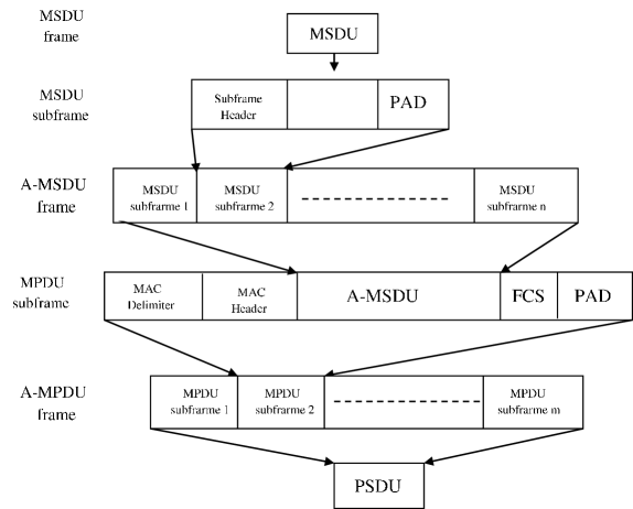
We focus on optimizing the TXOP duration and pattern, PPDU duration and the 11ax’s two-level aggregation scheme working point first introduced in IEEE 802.11n [30], in which several MPDUs can be aggregated to be transmitted in a single PHY Service Data Unit (PSDU). Such aggregated PSDU is denoted Aggregate MAC Protocol Data Unit (A-MPDU) frame. In two-level aggregation every MPDU can contain several MAC Service Data Units (MSDU). MPDUs are separated by an MPDU Delimiter field of 4 bytes and each MPDU contains MAC Header and Frame Control Sequence (FCS) fields. MSDUs within an MPDU are separated by a SubHeader field of 14 bytes. Every MSDU is rounded to an integral multiple of 4 bytes together with the SubHeader field. Every MPDU is also rounded to an integral multiple of 4 bytes.
In 11ax the size of an MPDU is limited to 11454 bytes and the size of the A-MPDU frame is limited to 4,194,304 bytes. The transmission time of the PPDU (PSDU and its preamble) is limited to () due to the L-SIG (one of the legacy preamble’s fields) duration limit [1]. The A-MPDU frame structure in two-level aggregation is shown in Figure 1.
IEEE 802.11ax also enables extension of the acknowledgment mechanism by using an acknowledgment window of 256 MPDUs. In this paper we also assume that all MPDUs transmitted in an A-MPDU frame are from the same Traffic Stream (TS). In this case up to 256 MPDUs are allowed in an A-MPDU frame of 11ax.
Finally, in 11ax it is possible to transmit/receive simultaneously to/from up to 74 stations over the DL/UL respectively using MU.
3 Model
3.1 HE scheduling strategies for TCP Usage
We compare between 11ax contention based Single User (SU), Reverse Direction (RD) SU and Multi User (MU) TCP DL unidirectional scheduling strategies in order to optimize the performance of DL single direction TCP connections, from the AP to stations.
3.1.1 Scheduling strategy 1 - HE DL Single User Reverse Direction unidirectional TCP
Recall that Reverse Direction (RD) is a mechanism by which the owner of a Transmission Opportunity (TXOP), the AP in our case, can enable its receiver to immediately transmit back the TCP Acks during the TXOP so that the receiver does not need to initiate UL transmission by using the Extended Distributed Coordination Function (EDCF) channel access method defined in IEEE 802.11e [1]. This is particularly efficient for bi-directional traffic such as TCP Data/Ack segments as it reduces overhead caused by collisions.
We examine a HE RD based scheduling strategy in which the AP transmits DL HE SU A-MPDU frames containing MPDUs of TCP Data segments to a station and enables the station to answer with an UL HE SU A-MPDU frame containing MPDUs frames of TCP Acks segments. Both the AP and the stations apply the two-level aggregation. We assume the following scenario to use RD, as is illustrated in Figure 2.
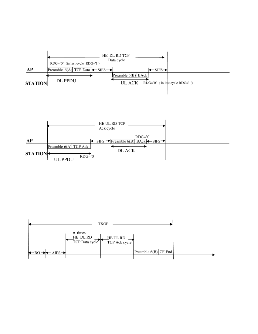
After waiting AIFS and BackOff according to the 802.11 air access EDCA procedure, the AP initiates a TXOP by transmitting DL HE SU A-MPDU frames in a row. Every such DL PPDU transmission, followed by receiving the BAck frame from the station, is denoted a HE DL RD TCP Data cycle. In its last DL HE SU A-MPDU frame the AP sets the RDG bit [1], enabling the station to respond with an UL HE SU A-MPDU frame containing TCP Ack segments. The AP then responds with a BAck frame and terminates the TXOP with the CF-End frame [1]. The transmission of the UL HE SU A-MPDU frame by the station, followed by the BAck transmission from the AP, is denoted a HE UL RD TCP Ack cycle.
In this HE RD based scheduling strategy we assume that there are no collisions and TXOP are repeated over the channel one after the other. This is made possible by configuring the stations in a way that prevents collisions. For example, the stations are configured to choose their BackOff intervals from very large contention intervals, other than the default ones [1]. Thus, the AP always wins over the channel without collisions.
In the case where the AP maintains TCP connections with stations in parallel, it transmits to the stations using Round Robin i.e. , after maintaining a TXOP with a station the AP initiates a TXOP with the next station and so on.
3.1.2 Scheduling strategy 2 - HE DL Single User contention based unidirectional TCP
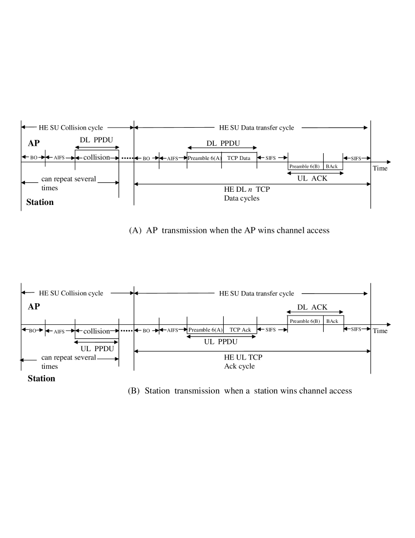
This HE SU scheduling strategy is shown in Figure 3. In this strategy the AP uses TXOPs but not RD: when the AP gets access to the channel it transmits DL HE SU A-MPDU frames containing TCP Data segments to a station in a row. Every transmission of a single DL HE SU A-MPDU frame from the AP is followed by a BAck frame transmission from the destination station; see Figure 3(A).
In this scheduling strategy both the AP and the stations contend in parallel for accessing the air channel in every transmission attempt, using the EDCF channel access method. In case the AP fails to gain access to the channel during its first attempt, it tries to access the channel again according to EDCF, with re-try penalty (longer BackOff interval) as shown in Figure 3(A).
The AP transmits to the stations in a Round Robin fashion. After transmitting TCP Data segments to a station, the AP does not serve that station again before receiving TCP Ack segments from the station and before the AP returns again to the station in the Round Robin order. Notice from the above that if the AP returns to a station in the Round Robin order before that station transmits TCP Ack segments to the AP, the AP skips over the station.
A station transmits to the AP only when it has TCP Ack segments, and it transmits the TCP Acks in one UL HE SU A-MPDU frame. See Figure 3(B).
3.1.3 Scheduling strategy 3 - HE DL simultaneous Multi User unidirectional TCP
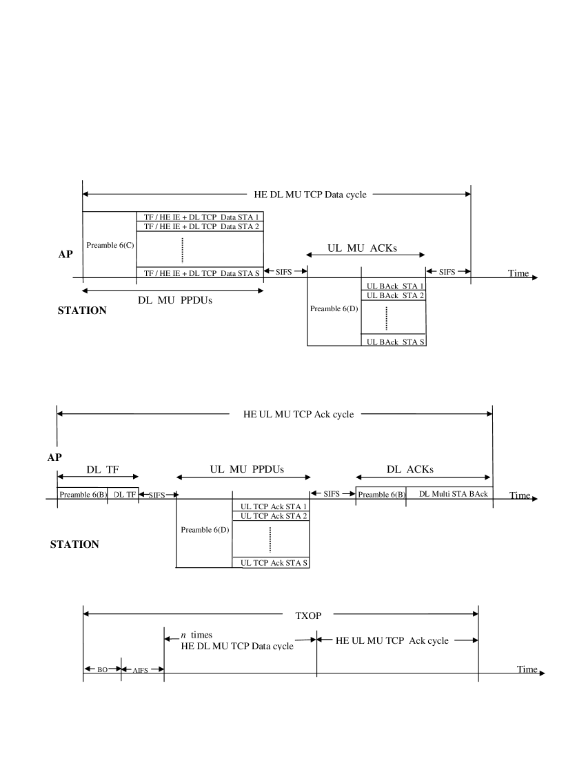
In the HE DL unidirectional TCP Multi User mode the AP transmits TCP Data to and receives TCP Acks from several stations in parallel. We assume the following DL unidirectional TCP where simultaneous DL TCP Data is sent by the AP to multiple stations in the same PPDU and the TCP Acks are sent simultaneously by the stations at the same TXOP by using Multi User, as is illustrated in Figure 4.
In this HE DL MU scheduling strategy, after waiting the BackOff and AIFS intervals, the AP receives an air access and starts a TXOP by transmitting DL HE MU A-MPDU frames containing TCP Data segments to a group of stations simultaneously. In every DL HE MU A-MPDU frame the AP transmits to a different set of stations in the group. After receiving the UL HE MU BAck frames from the group of stations simultaneously, the so-called HE DL MU TCP Data cycle ends and such a cycle can now repeats itself several times.
In order to transmit to a group of stations simultaneously, the AP allocates Resource Units (RU), i.e. sub-channels, per served station. RU allocation is done at the DL for TCP Data segments and at the UL for the TCP Acks. The AP signals the stations when and how to transmit, i.e. their UL RU allocation using one of two possible methods. In the first method the AP transmits a unicast Trigger Frame (TF) to every station that contains the UL RU allocation. This frame is a control MPDU frame that is added to the other Data MPDUs that the AP transmits to a station in a DL HE MU A-MPDU frame. The alternative method is to add an HE Control Element to MPDU in the DL HE MU A-MPDU frame that is transmitted to every station. In the following Goodput computations we optimize the amount of overhead used due to the above methods by computing the minimum overhead needed as a function of the number of data MPDUs in the DL HE MU A-MPDU frame.
At the end of the last HE DL MU TCP Data cycle the AP initiates a HE UL MU TCP Ack cycle by transmitting the broadcast Trigger Frame (TF). This TF solicits TCP Ack transmissions from the stations to the AP. At this transmission the stations transmit TCP Ack segments using UL HE MU A-MPDU frames. Every station transmits its TCP Ack segments in a different UL HE MU A-MPDU frame. The AP acknowledges the stations’ UL HE MU A-MPDU frames by generating and transmitting a single DL Multi Station BAck frame. At this stage the HE UL MU TCP Ack cycle ends and a new series of HE DL MU TCP Data cycle(s) and HE MU UL TCP Ack cycle begin.
As in the SU RD based scheduling strategy we assume that there are no collisions by increasing the size of the congestion interval from which the stations choose their EDCF BackOff extended interval.
3.2 IEEE 802.11 Frames/PPDU formats
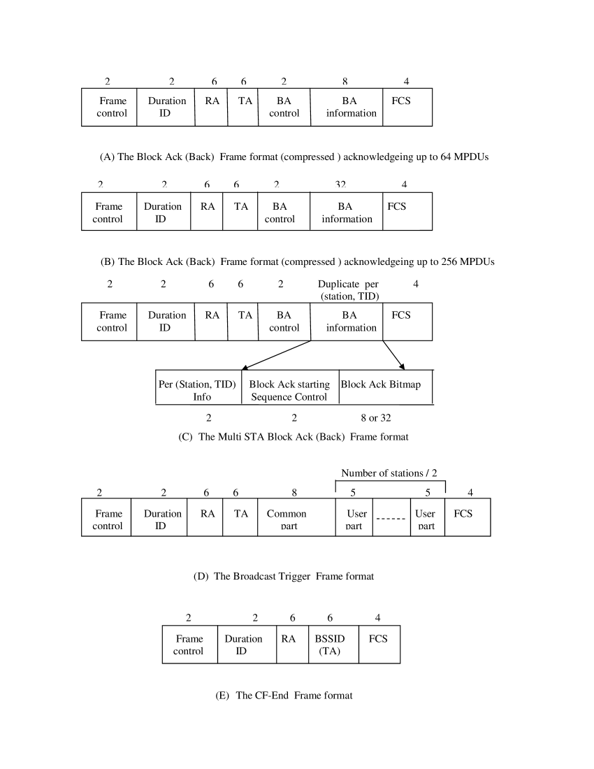
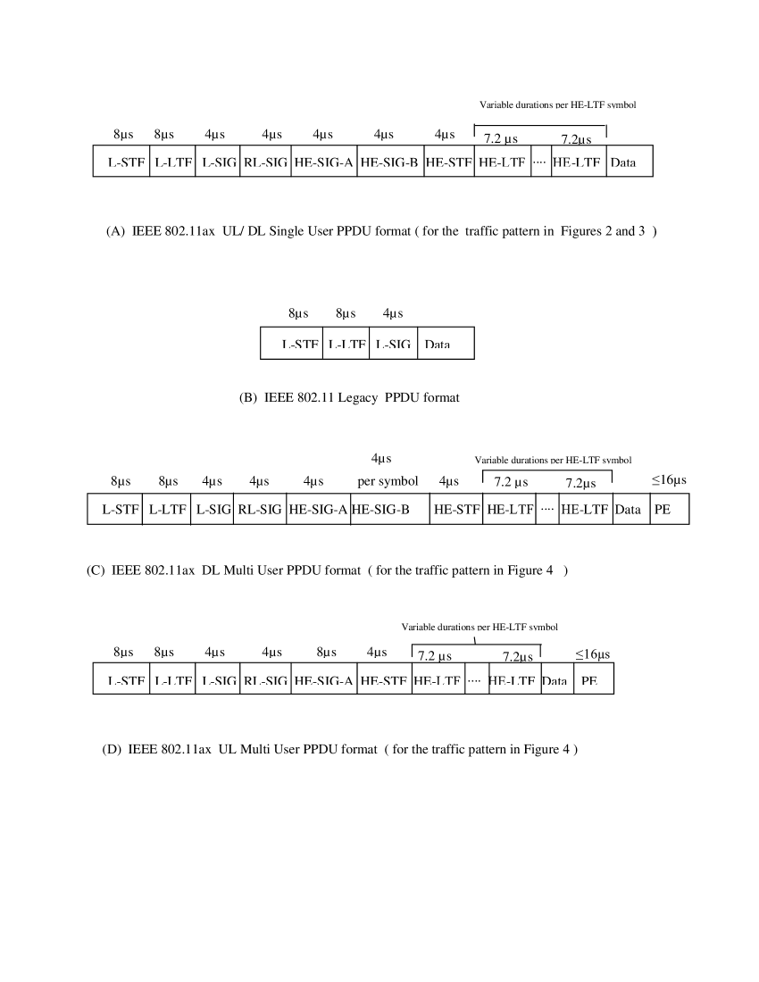
In Figure 5 we show the 802.11 frames’ formats of the BAck, Multi Station BAck, TF and CF-End frames used in the various scheduling strategies. In Figure 6 we show the various PPDUs’ formats used in the various scheduling strategies shown in Figures 2-4.
For the TCP Data/Ack segments’ transmission in Figure 2, scheduling strategy 1, the PPDU format in Figure 6(A) is used while the BAck and CF-End frames are transmitted using the legacy mode in Figure 6(B).
For the TCP Data/Ack segments’ transmission in Figure 3, scheduling strategy 2, the PPDU in Figure 6(A) is used while the BAck frames are transmitted by the legacy mode shown in Figure 6(B).
For the TCP DL Data segments’ transmission in Figure 4, scheduling strategy 3, the PPDU format in Figure 6(C) is used and the BAcks are transmitted using the PPDU format in Figure 6(D). The TCP UL Ack segments are transmitted by the PPDU format in Figure 6(D) and the TF and DL Multi Station Ack frames are transmitted by the legacy PPDU format in Figure 6(B).
In the 11ax PPDU formats we find the HE-LTF fields, the number of which equals the number of SSs in use; 4 in our case. In this paper we assume that each such field is composed of 2X LTF and therefore of duration [2].
Notice also that the PSDU frame in 11ax contains a Packet Extension (PE) field. This field is mainly used in MU mode and we assume that it is in SU and the longest possible in MU, .
In the HE-SIG-B field used in the PPDU format of Figure 6(C) the Modulation/Coding Scheme (MCS) that is used for this field is the minimum between MCS4 and the one used for the data transmissions [2]. The length of this field is also a function of the number of stations to which the AP transmits simultaneously. Therefore, in the case of 4 stations for example, the HE-SIG-B field duration is for MCS0 and MCS1 and for MCS2-4 following section 23.3.9.8 in [2]. For MCS5-MCS11 it is as for MCS4.
3.3 Parameters’ values
We assume the 5GHz band, a 160MHz channel and that the AP and each station has 4 antennae. In SU mode, i.e. in scheduling strategies 1 and 2, the AP and the stations use up to 4 Spatial Streams and the entire channel is devoted to transmissions of the AP and stations. The BAck frames are transmitted using legacy mode and the basic rates’ set is used. The PHY rate is set to the largest basic rate that is smaller or equal to the TCP Data/Ack segments’ transmission rate .
In Table 1 we show the PHY rates and the length of preambles used in SU mode in scheduling strategies 1 and 2 and in the various MCSs. The values are taken from [2].
| 1 | 2 | ||||
| SU UL/DL data | SU UL/DL BAck | ||||
| transmission rate | transmission rate | ||||
| PHY Rate | Preamble | PHY Rate (legacy) | Preamble | ||
| MCS | (Mbps) | () | (Mbps) | () | |
| GI | GI | ||||
| 0 | 288.2 | 64.8 | 48.0 | 20.0 | |
| 1 | 576.5 | 64.8 | 48.0 | 20.0 | |
| 2 | 864.7 | 64.8 | 48.0 | 20.0 | |
| 3 | 1152.9 | 64.8 | 48.0 | 20.0 | |
| 4 | 1729.4 | 64.8 | 48.0 | 20.0 | |
| 5 | 2305.9 | 64.8 | 48.0 | 20.0 | |
| 6 | 2594.1 | 64.8 | 48.0 | 20.0 | |
| 7 | 2882.4 | 64.8 | 48.0 | 20.0 | |
| 8 | 3458.8 | 64.8 | 48.0 | 20.0 | |
| 9 | 3848.1 | 64.8 | 48.0 | 20.0 | |
| 10 | 4323.5 | 64.8 | 48.0 | 20.0 | |
| 11 | 4803.9 | 64.8 | 48.0 | 20.0 | |
When using MU mode in scheduling strategy 3, the 160MHz channel is divided into channels of MHz each, . When the 160MHz is used in MU-MIMO. For MU-MIMO+OFDMA is used. The AP transmits over the DL to 4 stations in every such channel, by allocating a single Spatial Stream per station i.e. in every channel 4 Spatial Streams are allocated. For example, for there are 16 channels of 10MHz each; in each one the AP transmits to 4 stations. The stations transmit to the AP over the UL in a symmetrical way to that of the AP over the DL.
The TF and the Multi Station BAck frames are transmitted using the legacy mode and the PHY rate is set to the largest basic rate that is smaller or equal to the TCP Data/Ack segments’ transmission rate . The minimal basic PHY rate is 6Mbps. In the case of smaller than 6Mbps, is never less than 6Mbps. This can occur in the case of 64 stations.
In Table 2 we show the PHY rates and the preambles used in scheduling strategy 3, in the various MCSs and in all cases of the number of stations , i.e. and 64.
| 1 | 2 | 3 | |||||
| MU UL data | MU DL data | DL TF/Multi Station BAck | |||||
| transmission rate | transmission rate | transmission rate | |||||
| PHY Rate | Preamble | PHY Rate | Preamble | PHY Rate (legacy) | Preamble | ||
| MCS | (Mbps per 1 SS) | () | (Mbps per 1 SS) | () | (Mbps) | () | |
| GI | GI | GI | |||||
| 4 stations | |||||||
| 0 | 68.1 | 64.8 | 72.1 | 72.8 | 48.0 | 20.0 | |
| 1 | 136.1 | 64.8 | 144.1 | 72.8 | 48.0 | 20.0 | |
| 2 | 204.2 | 64.8 | 216.2 | 68.8 | 48.0 | 20.0 | |
| 3 | 272.2 | 64.8 | 288.2 | 68.8 | 48.0 | 20.0 | |
| 4 | 408.3 | 64.8 | 432.4 | 68.8 | 48.0 | 20.0 | |
| 5 | 544.4 | 64.8 | 576.5 | 68.8 | 48.0 | 20.0 | |
| 6 | 612.5 | 64.8 | 648.5 | 68.8 | 48.0 | 20.0 | |
| 7 | 680.6 | 64.8 | 720.6 | 68.8 | 48.0 | 20.0 | |
| 8 | 816.7 | 64.8 | 864.7 | 68.8 | 48.0 | 20.0 | |
| 9 | 907.4 | 64.8 | 960.7 | 68.8 | 48.0 | 20.0 | |
| 10 | 1020.8 | 64.8 | 1080.4 | 68.8 | 48.0 | 20.0 | |
| 11 | 1134.2 | 64.8 | 1201.0 | 68.8 | 48.0 | 20.0 | |
| 8 stations | |||||||
| 0 | 34.0 | 64.8 | 36.0 | 76.8 | 36.0 | 20.0 | |
| 1 | 68.1 | 64.8 | 72.1 | 76.8 | 48.0 | 20.0 | |
| 2 | 102.1 | 64.8 | 108.1 | 72.8 | 48.0 | 20.0 | |
| 3 | 136.1 | 64.8 | 144.1 | 72.8 | 48.0 | 20.0 | |
| 4 | 204.2 | 64.8 | 216.2 | 68.8 | 48.0 | 20.0 | |
| 5 | 272.2 | 64.8 | 288.2 | 68.8 | 48.0 | 20.0 | |
| 6 | 306.3 | 64.8 | 324.3 | 68.8 | 48.0 | 20.0 | |
| 7 | 340.3 | 64.8 | 360.3 | 68.8 | 48.0 | 20.0 | |
| 8 | 408.3 | 64.8 | 432.4 | 68.8 | 48.0 | 20.0 | |
| 9 | 453.7 | 64.8 | 480.4 | 68.8 | 48.0 | 20.0 | |
| 10 | 510.4 | 64.8 | 540.4 | 68.8 | 48.0 | 20.0 | |
| 11 | 567.1 | 64.8 | 600.4 | 68.8 | 48.0 | 20.0 | |
| 16 stations | |||||||
| 0 | 16.3 | 64.8 | 17.2 | 84.8 | 12.0 | 20.0 | |
| 1 | 32.5 | 64.8 | 34.4 | 84.8 | 12.0 | 20.0 | |
| 2 | 48.8 | 64.8 | 51.6 | 76.8 | 24.0 | 20.0 | |
| 3 | 65.0 | 64.8 | 68.8 | 76.8 | 48.0 | 20.0 | |
| 4 | 97.5 | 64.8 | 103.2 | 72.8 | 48.0 | 20.0 | |
| 5 | 130.0 | 64.8 | 137.6 | 72.8 | 48.0 | 20.0 | |
| 6 | 146.3 | 64.8 | 154.9 | 72.8 | 48.0 | 20.0 | |
| 7 | 162.5 | 64.8 | 172.1 | 72.8 | 48.0 | 20.0 | |
| 8 | 195.0 | 64.8 | 206.5 | 72.8 | 48.0 | 20.0 | |
| 9 | 216.7 | 64.8 | 229.4 | 72.8 | 48.0 | 20.0 | |
| 10 | 243.8 | 64.8 | 258.1 | 72.8 | 48.0 | 20.0 | |
| 11 | 270.8 | 64.8 | 286.8 | 72.8 | 48.0 | 20.0 | |
| 1 | 2 | 3 | |||||
| MU UL data | MU DL data | DL TF/Multi Station BAck | |||||
| transmission rate | transmission rate | transmission rate | |||||
| PHY Rate | Preamble | PHY Rate | Preamble | PHY Rate (legacy) | Preamble | ||
| MCS | (Mbps per 1 SS) | () | (Mbps per 1 SS) | () | (Mbps) | () | |
| GI | GI | GI | |||||
| 32 stations | |||||||
| 0 | 8.1 | 64.8 | 8.6 | 104.8 | 6.0 | 20.0 | |
| 1 | 16.3 | 64.8 | 17.2 | 104.8 | 12.0 | 20.0 | |
| 2 | 24.4 | 64.8 | 25.8 | 84.8 | 24.0 | 20.0 | |
| 3 | 32.5 | 64.8 | 34.4 | 84.8 | 24.0 | 20.0 | |
| 4 | 48.8 | 64.8 | 51.6 | 80.8 | 48.0 | 20.0 | |
| 5 | 65.0 | 64.8 | 68.8 | 80.8 | 48.0 | 20.0 | |
| 6 | 73.1 | 64.8 | 77.4 | 80.8 | 48.0 | 20.0 | |
| 7 | 81.3 | 64.8 | 86.0 | 80.8 | 48.0 | 20.0 | |
| 8 | 97.5 | 64.8 | 103.2 | 80.8 | 48.0 | 20.0 | |
| 9 | 108.3 | 64.8 | 114.7 | 80.8 | 48.0 | 20.0 | |
| 10 | 121.9 | 64.8 | 129.0 | 80.8 | 48.0 | 20.0 | |
| 11 | 135.4 | 64.8 | 143.4 | 80.8 | 48.0 | 20.0 | |
| 64 stations | |||||||
| 0 | 3.5 | 64.8 | 3.8 | 136.8 | 6.0 | 20.0 | |
| 1 | 7.1 | 64.8 | 7.5 | 136.8 | 6.0 | 20.0 | |
| 2 | 10.6 | 64.8 | 11.3 | 100.8 | 9.0 | 20.0 | |
| 3 | 14.2 | 64.8 | 15.0 | 100.8 | 12.0 | 20.0 | |
| 4 | 21.3 | 64.8 | 22.5 | 88.8 | 18.0 | 20.0 | |
| 5 | 28.3 | 64.8 | 30.0 | 88.8 | 24.0 | 20.0 | |
| 6 | 31.9 | 64.8 | 33.8 | 88.8 | 24.0 | 20.0 | |
| 7 | 35.4 | 64.8 | 37.5 | 88.8 | 24.0 | 20.0 | |
| 8 | 42.5 | 64.8 | 45.0 | 88.8 | 36.0 | 20.0 | |
| 9 | 47.2 | 64.8 | 50.0 | 88.8 | 36.0 | 20.0 | |
| 10 | N/A | N/A | N/A | N/A | N/A | N/A | |
| 11 | N/A | N/A | N/A | N/A | N/A | N/A | |
We assume the Best Effort Access Category in which for the AP and for a station, and for the transmissions of the AP. Recall that in scheduling strategies 1 and 3 we assume there are no collisions between the AP and the stations. The BackOff interval is a random number chosen uniformly from the range . Since we consider a very ’great’ number of transmissions from the AP in scheduling strategies 1 and 3, we take the BackOff average value of , and the average BackOff interval for the AP is which equals for a .
Concerning the transmission in non-legacy mode, an OFDM symbol is . In the DL we assume a GI of and therefore the symbol in this direction is . In the UL MU we assume a GI of and therefore the symbol in this direction is . The UL GI is due to UL arrival time variants. In UL SU the GI is . When considering transmissions in legacy mode, the symbol is containing a GI of .
We assume that the MAC Header field is of 28 bytes and the Frame Control Sequence (FCS) field is of 4 bytes. Finally, we assume TCP Data segments of and bytes. Therefore, the resulting MSDUs’ lengths are and bytes respectively ( 20 bytes of TCP header plus 20 bytes of IP header plus 8 bytes of LLC SNAP are added ). Together with the SubHeader field and rounding to an integral multiple of 4 bytes, every MSDU is now of and bytes respectively. Due to the limit of 11454 bytes on the MPDU size, 7, 21 and 42 such MSDUs are possible respectively in one MPDU.
The TCP receiver transmits TCP Acks. Every MSDU containing a TCP Ack is of bytes ( 20 bytes of TCP Header + 20 bytes of IP header + 8 bytes of LLC SNAP ). Adding 14 bytes of the SubHeader field and rounding to an integral multiple of 4 bytes, every MSDU is of bytes, and every single MPDU, again due to the size limit of 11454 bytes, can contain up to 178 MSDUs (TCP Acks). Thus, the receiver can transmit up to TCP Acks in a single HE UL A-MPDU frame.
4 Goodput analysis
The system Goodput analysis has two targets. The first is to find the optimal working point for each of the proposed scheduling strategies, i.e. finding the working point that maximizes the Goodput of a TXOP. By an optimal working point we refer to the number of DL TCP Data MSDUs to transmit in a TXOP, how many HE DL TCP Data cycles to transmit in a TXOP, and the optimal HE DL A-MPDU structure within each HE DL TCP Data cycle i.e. the number of MPDUs in the HE DL A-MPDU and the number of MSDUs within every MPDU.
Notice that the Goodput computed is actually the system TCP Goodput, i.e. the average number of TCP Data bits that are transmitted in the system per time unit. However, in SU, scheduling strategies 1 and 2, when stations are served by the AP, a single station enjoys a given TCP Googput in every TXOP only. The system provides a TCP Goodput to all the stations over TXOPs. In the MU strategy, scheduling strategy 3, the TCP Goodput of a TXOP is that provided to all the stations together over one TXOP.
The second target of the analysis is to find the time intervals over which the system enables a given TCP Goodput to all of its stations. A scheduling strategy that enables a given TCP Goodput to all stations over shorter time intervals is more efficient.
4.1 Maximum Goodput of a TXOP
Computing the optimal working point per scheduling strategy, i.e. the one that maximizes the Goodput of a TXOP, is done in 3 stages:
-
1.
The number of TCP Data segments that can be transmitted in a TXOP is limited by the number TCP Ack segments that can be transmitted in one HE UL A-MPDU frame. The number 256 is the Block Ack window size and 178 is the number of TCP Ack segments possible in one MPDU. was computed in Section 3.3 and if more than TCP Data segments are transmitted in a TXOP, stations begin to accumulate TCP Acks and the Goodput decreases.
-
2.
In order to maximize the Goodput the TCP Acks shall be transmitted in the minimal possible number of MPDUs in order to minimize overhead associated with MPDUs containing TCP Acks. For TCP Acks, the number of MPDUs is . See Section 3.3 .
-
3.
For every number of TCP Data segments transmitted in a TXOP, , it is necessary to determine what is the number of HE DL A-MPDU frames for transmission in a TXOP, and the structure of each HE DL A-MPDU frame, i.e. how many MPDUs are in every HE DL A-MPDU frame and how many MSDUs are in every MPDU. This is necessary in order to minimize overhead associated with MPDU and HE DL A-MPDU frames that contain TCP Data segments. This computation is carried on in the appendix.
For scheduling strategies 1 and 3 we provide a mathematical analysis to compute the Goodput of a TXOP. This analysis was verified by the NS3 simulator. The analysis and simulation results match perfectly. This is not surprising as there is no stochastic process in these strategies. Therefore, we later omit their simulation results. For scheduling strategy 2 we only use simulation to compute the Goodput.
4.1.1 Goodput analysis for scheduling strategy 1 - HE DL Single User Reverse Direction unidirectional TCP
For this HE SU RD scheduling strategy notice that TCP Acks that a station can transmit in one HE UL RD TCP Ack cycle is an upper bound on the number of DL TCP Data MSDUs that can be transmitted by the AP in a TXOP. Using a larger number will cause the receiver to accumulate TCP Acks and the Goodput to decrease. See Section 3.3 .
An HE SU RD TXOP has a fixed overhead of the AIFS and BackOff intervals, and the transmission time of the CF-End frame and its associated preamble 6(B). In addition there are overheads associated with the transmission of an MPDU frame and a HE DL SU A-MPDU frame. The MPDU’s overhead is composed of the MAC Header, MPDU Delimiter and the FCS fields. The HE DL SU A-MPDU overhead for scheduling strategy 1 is . See Figure 2 .
Due to the various overheads it may not always be worthwhile to transmit TCP Data MSDUs in a TXOP. For instance, a single MSDU can cause the creation of both a new HE DL SU A-MPDU and an MPDU with all of the associated overhead that overall can reduce the Goodput.
Assume that TCP Data MSDUs are transmitted in a TXOP. For a reliable clearly it is most efficient to transmit the TCP Ack MSDUs in the smallest number of MPDUs, i.e. in MPDUs. This will reduce the overhead associated with MPDUs containing TCP Ack MSDUs to a minimum. Recall that all the TCP Ack MSDUs are transmitted in one HE UL SU A-MPDU frame.
Recall now that in the appendix we show how to schedule TCP Data MSDUs in the most efficient way in a TXOP, i.e. the scheduling that results in the smallest HE UL SU A-MPDUs’ and MPDUs’ overheads. Assume that the optimal scheduling of TCP Data MSDUs is in HE DL SU A-MPDUs. Let and be the numbers of MPDUs and MSDUs respectively in HE DL SU A-MPDU number .
Let and denote the length, in , of the AIFS and average BackOff intervals. Let be the total length, in bytes, of the MAC Header, MPDU Delimiter and FCS fields. The Goodput of scheduling strategy 1 is given by Eq. 1, assuming the AP transmits TCP Data MSDUs in HE DL SU RD TCP Data cycles:
| (1) |
Where:
| (2) |
and are the transmission times of the BAck and the CF-End frames respectively. The times are based on the frames’ lengths shown in Figure 5. assumes the BAck frame acknowledging 256 MPDUs, Figure 5(B). If the number of MPDUs is smaller than or equal to 64, the BAck frame of Figure 5(A) is used, and in this case the term 54 in the numerator of is replaced by 30.
and are the lengths of the OFDM symbols in the DL and UL respectively, including the GI, when transmitting in a non-legacy mode, and every transmission must be of an integral number of OFDM symbols. and it is the length of the OFDM symbol that is used in legacy transmissions. and are the PHY rates for TCP Data/Ack transmissions on the DL and the UL respectively, and is the legacy PHY rate used for the transmission of the BAck and CF-End frames. See Table 1. The additional 22 bits in the various numerators of the frames’ transmission times are due to the SERVICE and TAIL fields that are added to every transmission by the PHY layer conv. protocol [1].
4.1.2 Goodput analysis for Scheduling strategy 2 - HE DL Single User contention based unidirectional TCP
In this scheduling strategy the AP transmits DL TCP Data segments, , to a station after accessing the channel. The number of HE DL SU A-MPDU frames containing these TCP Data segments and their structure is determined as in scheduling strategy 1. The AP does not transmit to a station again before it receives UL TCP Acks from the station and transmits to the stations in Round Robin fashion. We check the performance of this scheduling strategy for various values of , the number of DL TCP Data segments that the AP transmits in one transmission to the station, .
4.1.3 Goodput analysis for Scheduling strategy 3 - HE DL simultaneous Multi User unidirectional TCP
In scheduling strategy 3 every single DL TCP connection between the AP and a station can be considered as the TCP connection in scheduling strategy 1. The only difference is that in scheduling strategy 3 the AP can transmit in several DL TCP connections parallel to several stations, and several stations can transmit their BAck and UL TCP Ack segments parallel to the AP. The analysis in scheduling strategy 3 is therefore basically the same as for scheduling strategy 1 with some differences specified below.
The Goodput of scheduling strategy 3 shown in Figure 4 is given by Eq. 3, assuming the AP transmits DL TCP Data MSDUs in every TCP connection in HE DL MU A-MPDUs:
| (3) |
where:
| (4) |
The quantity 4 in the numerator of the second term in stands for the HE IE added to every MPDU in order to schedule parallel transmissions of the BAck frames from the stations on the UL. This holds for . For it is more efficient to contain a unicast TF frame of length 72 bytes, containing the unicast TF frame (33 bytes) and the MAC Header, MPDU Delimiter and FCS fields, and rounding to an integral multiple of 4 bytes.
, and are the transmission times of the BAck, multicast TF and the Multi Station BAck frames respectively. is based on the Multi Station BAck frame length given in Figure 5(C) assuming the acknowledgment of 256 MPDUs per HE DL A-MPDU frame. When considering the acknowledgment of 64 MPDUs the term 36 in the numerator is replaced by 12. The term in and denote the number of stations transmitting data simultaneously over the UL.
and are the lengths of the OFDM symbols, containing the GIs, used over the UL and DL respectively when transmitting in non-legacy mode, and every transmission must be of an integral number of OFDM symbols. and it is the length of the OFDM symbol that is used in legacy transmissions. and are the DL and UL PHY rates respectively used for the transmission of TCP Data and TCP Acks segments. is the legacy PHY rate used for the transmission of the TF and Multi Station BAck frames. The additional 22 bits in the various numerators of the frames’ transmission times are due to the SERVICE and TAIL fields that are added to every transmission by the PHY layer conv. protocol [1].
4.2 Goodput vs. delay computation
For scheduling strategies 1 and 3 we measured the Goodput received in every TXOP according to Eqs. 2 and 4 respectively. In these equations the total number of TCP Data bits transmitted in a TXOP is divided by the TXOP length, measured in seconds. However, since we assume that the same TXOPs repeat themselves one after another, the computed Goodput of a TXOP is also the Goodput of the system.
We now measure for every number of TCP Data segments transmitted in a TXOP, the resulted length of the TXOP interval containing the TCP Data segments’ and as mentioned the Goodput is computed using Eqs. 2 and 4 respectively.
For scheduling strategy 2 we also measure the Goodput when transmitting TCP Data segments. However, in this scheduling strategy there is no TXOP with RD and instead we measure the average time elapsed from the time the AP transmits to a station TCP Data segments until it receives TCP Acks from the station.
From now on we denote by cycle the TXOPs in scheduling strategies 1 and 3, and the above time interval that we described for scheduling strategy 2. By cycle length we denote the length, in seconds, of the cycle.
The next step is as follows: Notice that for every number of TCP Data segments transmitted in a cycle, there is a resulting cycle length which shows how much time is needed in a cycle for the transmission of these TCP Data segments to a specific station. Thus, for every number of TCP Data segments, we attach two measures: the cycle length in which these TCP Data segments are transmitted and the resulting Goodput. We now arrange the cycle lengths in a list together with the associated Goodputs in increasing order of the cycle lengths.
Notice that two different cycle lengths can have the same Goodput. One of the cycles has more TCP Data segments but it can also have more A-MPDU/MPDUs’ overhead. IN addition, the number of TCP Data segments can be large enough so that the addition of one more TCP Data segment barely changes the Goodput. For a set of cycle lengths with the same Goodput we leave only the shortest cycle in the list.
Consider now a cycle length of L ms with a Goodput . In scheduling strategies 1 and 2 (the SU ones) when the AP is communicating with stations in Round Robin, a station receives TCP Data segments in every cycle. Thus, a station receives a service for L ms with a Goodput , and then waits before receiving TCP Data segments again. In total the system provides a Goodput for all stations during an interval of .
In scheduling strategy 3 (the MU one) where stations transmit in a TXOP, every station has a Goodput during an interval of . Overall the system provides a Goodput to all the stations during every interval of .
5 Goodput results
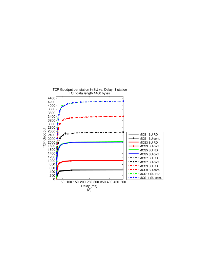
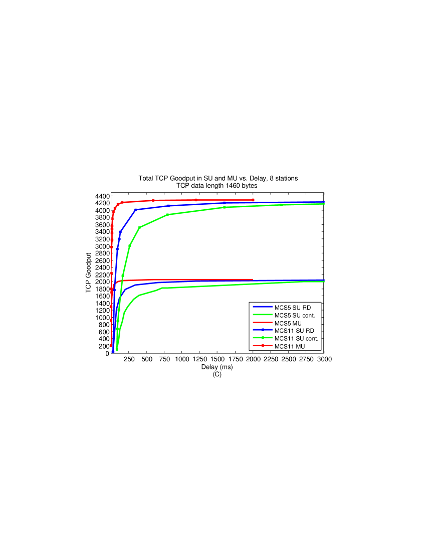
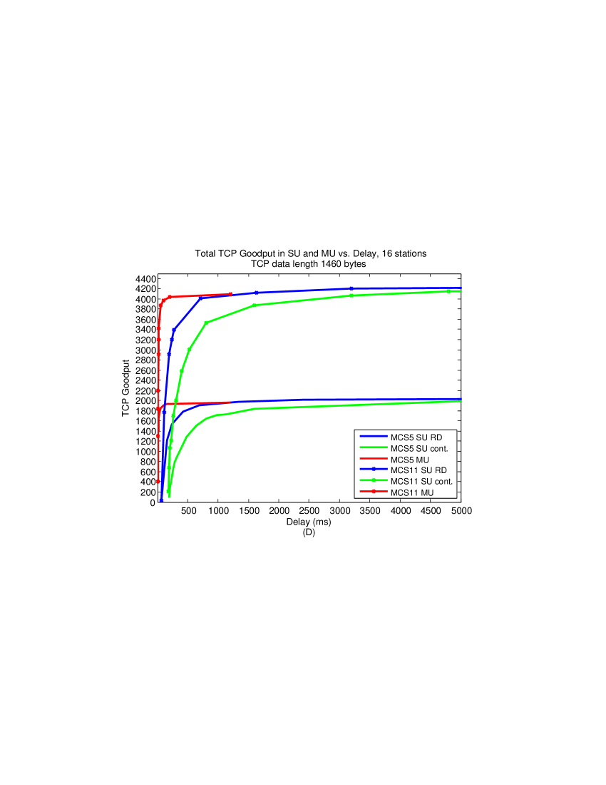
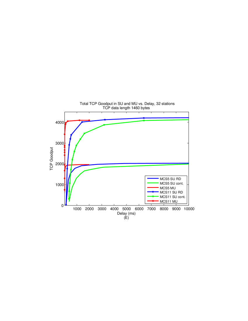
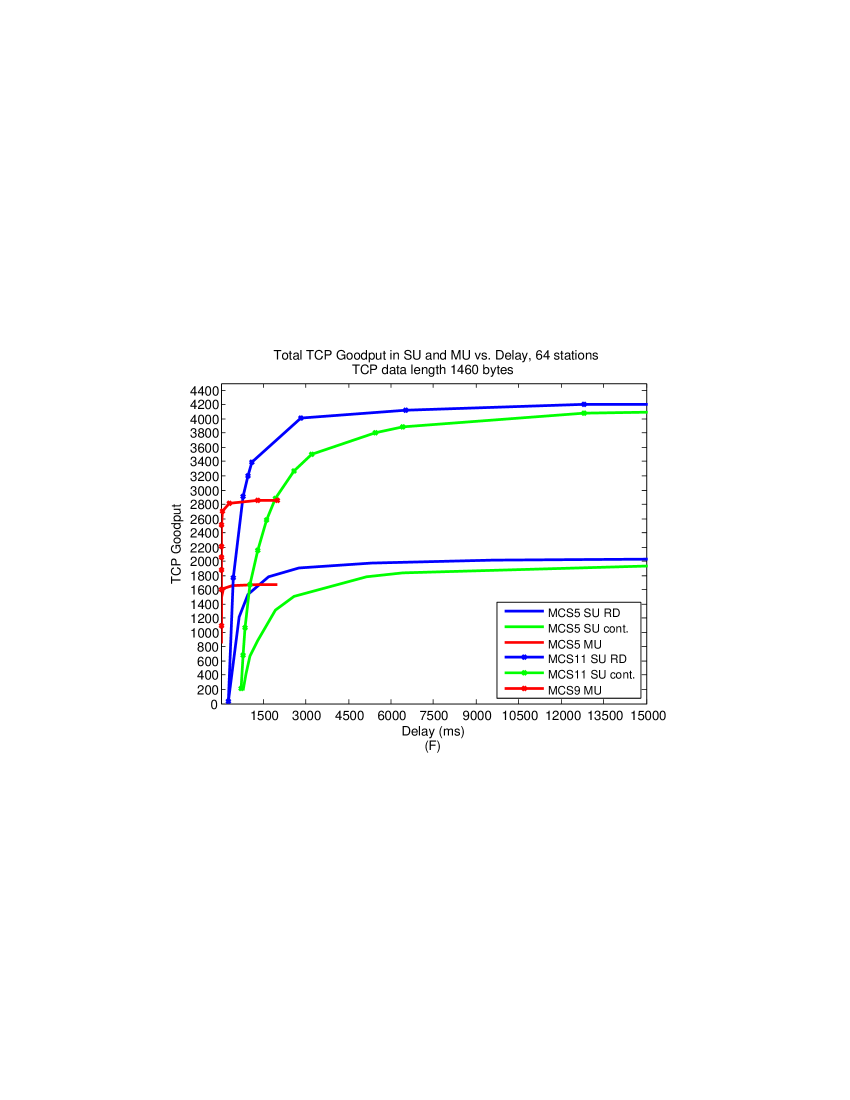
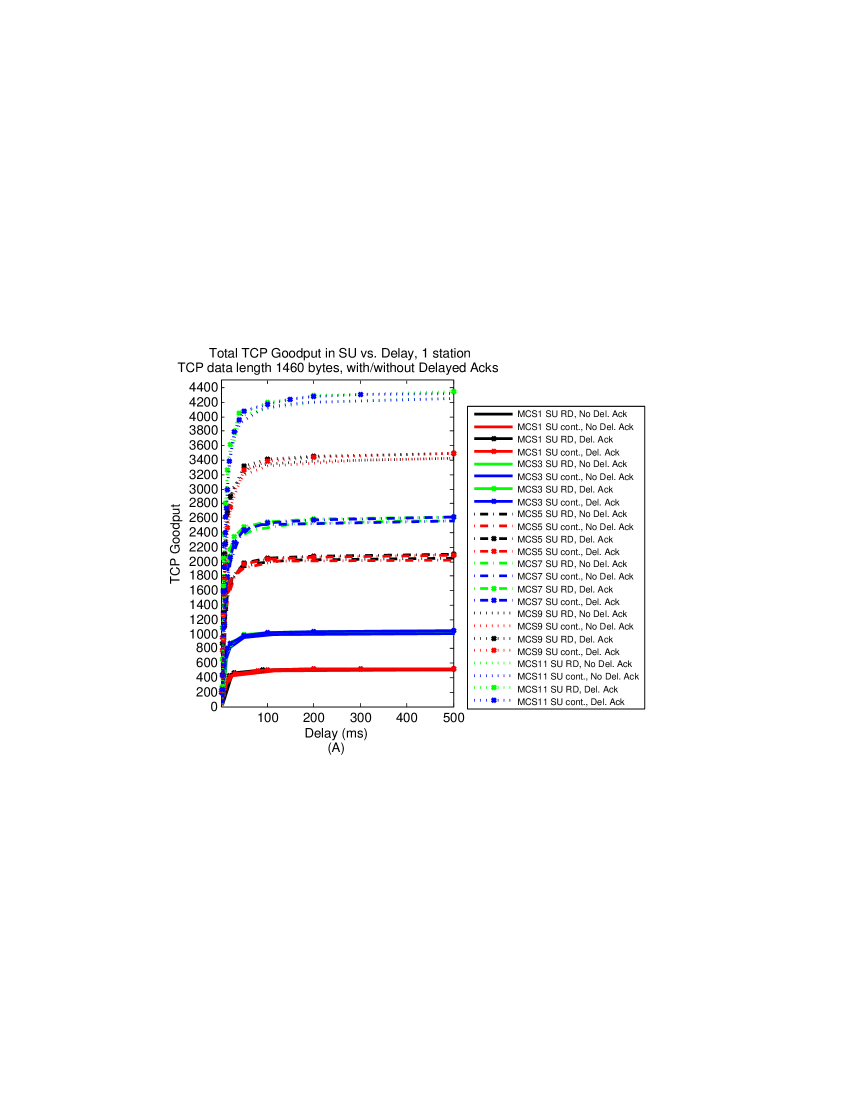
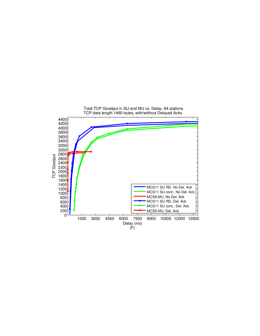
In Figure 7 we plot 6 graphs showing the Goodput of the system vs. the delay (cycle length) for the cases of and 64 stations in Figures 7(A), (B), (C), (D), (E) and (F) respectively, for TCP Data segments of length 1460 bytes and for the case where Delayed Acks are not used, i.e. every TCP Ack acknowledges one TCP Data segment. The results for TCP Data segments of 464 and 208 bytes are similar. As mentioned, the graphs for scheduling strategies 1 and 3 were obtained by analysis and simulation. The results for scheduling strategy 2 were obtained by simulation only.
In Figure 7(A) we show results for a single station and therefore only scheduling strategies 1 and 2 are relevant. We show results for MCSs 1, 3, 5, 7, 9 and 11. We see that the two scheduling strategies have similar results because there are no collisions in scheduling strategy 2 - the AP and the single station transmit alternately.
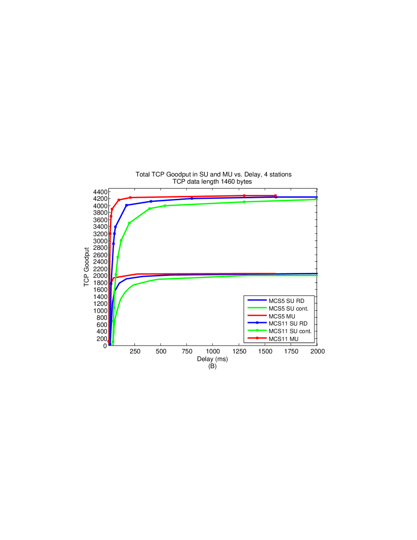
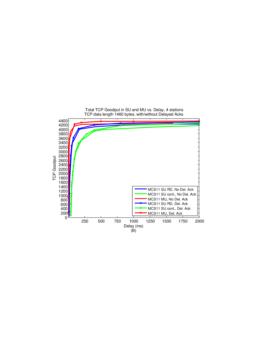
In Figure 7(B) we show results for 4 stations and for MCSs 5 and 11, this time for all the scheduling strategies. The results for all the other MCSs are similar. We see that the maximum Goodput is received in MU for about while in SU the same maximum Goodput is received in much longer times, i.e. more TCP Data segments need to be transmitted. Therefore, the MU strategy outperforms the SU strategies, while using RD outperforms the contention based strategy. We can therefore conclude that the MU uses the channel more efficiently in this case, and enables a better performance for TCP than SU.
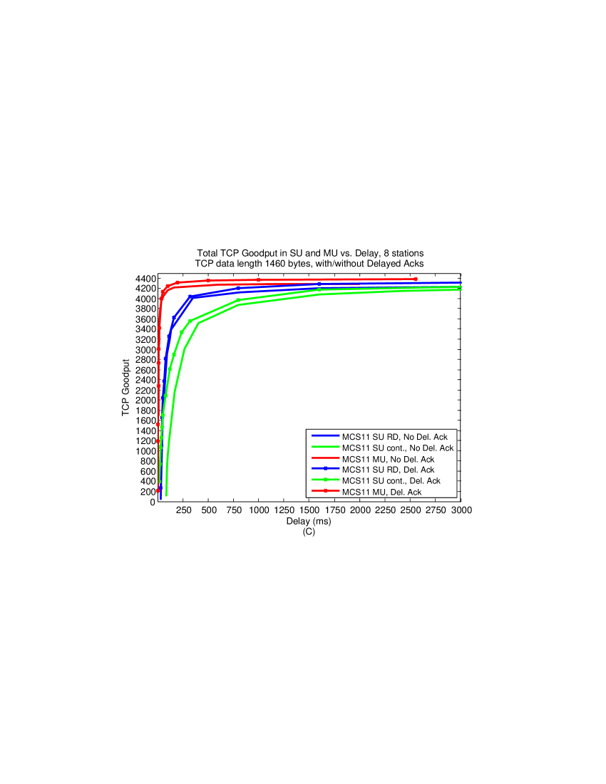
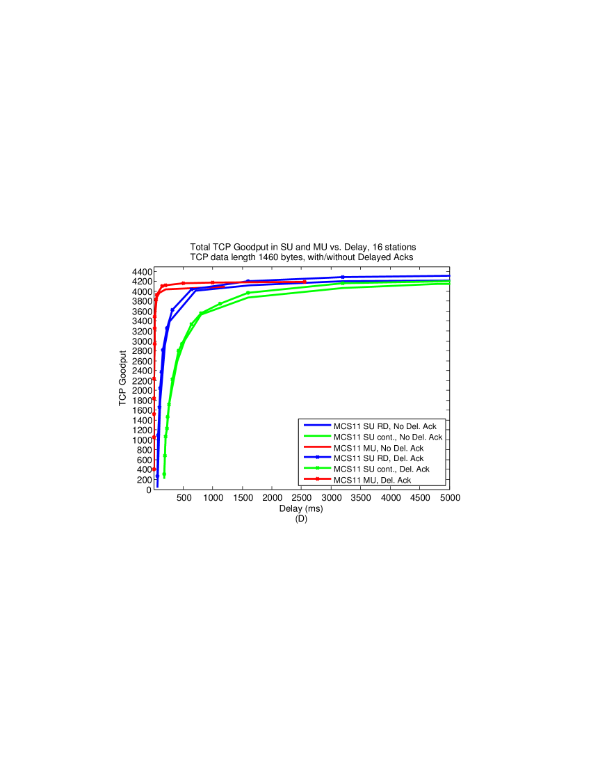
The same result also holds for 8 stations, Figure 7(C). In the case of 16 stations the MU strategy almost achieves the maximum Goodput. The RD strategy achieves the maximum Goodput, although in much larger delays. The MU strategy has small PHY rates that do not enable transmission of many TCP Acks due to the limit on transmission time of the HE UL MU A-MPDU frame containing the TCP Acks. As a consequence the number of TCP Data segments that can be transmitted in a TXOP is relatively small. Therefore, it is not possible to transmit as many TCP Data segments in a TXOP as in the SU strategies, and the resulting Goodput is smaller.
Notice that the above phenomena is also observed in the case of 32 stations, Figure 7(E). In Figure 7(F), the case for 64 stations, the very small PHY rates in MU cause the SU modes to outperform MU significantly.
In Figure 8 we show the same results as in Figure 7, this time with results for the Delayed Acks feature. For 4, 8, 16, 32 and 64 stations we show results only for MCS11. It can be concluded that the improvement in the Goodput is only marginal. Using Delayed Acks enables transmission of more TCP Data segments in a cycle. However, there is no save in the overhead of A-MPDUs and MPDUs containing TCP Data segments. There is only a small save in the overhead involved in the transmission of the TCP Acks, which is marginal, and so is the Goodput gain.
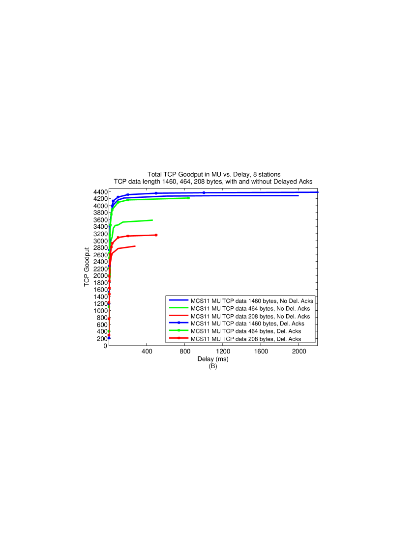
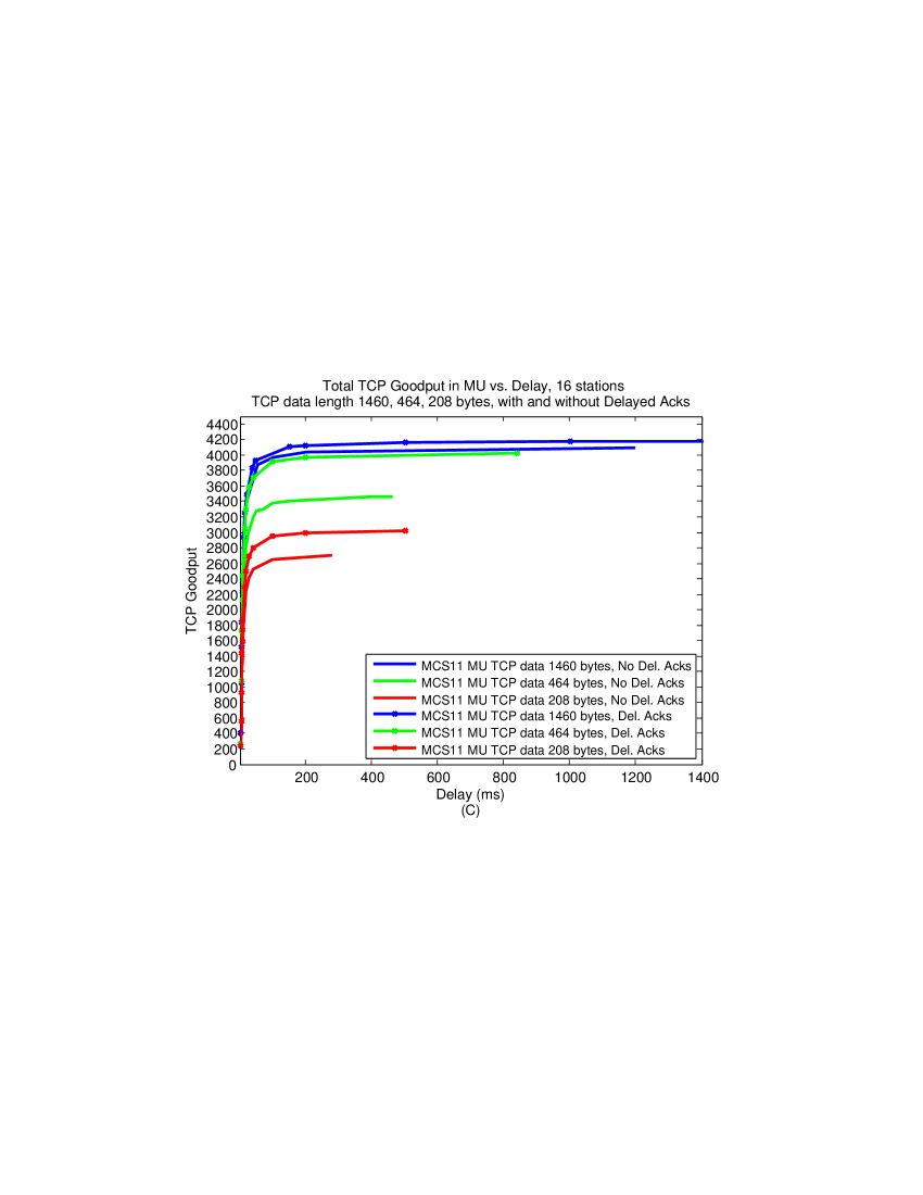
In Figure 9 we show results for the various TCP Data segments’ sizes, 208, 464 and 1460 bytes for MCS11, for the cases of 4, 8 and 16 stations in Figures 8 (A), (B) and (C) respectively. We also show results with and without Delayed Acks. Since the number of TCP Acks that can be transmitted in a cycle does not change, one can expect that as the length of the TCP Data segments decreases, the length of the respective cycles also decrease. This also is true for the respective Goodputs since the overhead of transmitting TCP Ack segments remains unchanged.
We see these expected results in Figure 9. Notice that for all cases the curves end at the longest cycles possible and these lengths decrease as the TCP Data segment lengths decrease.
We can also see that while for TCP Data segments of 1460 bytes the use of Delayed Acks results only in marginal Goodput improvement, the other TCP Data segments’ lengths such as 464 and 208 bytes show significant improvement. in the order of . With short TCP Data segments one can add many such segments without increasing the number of MPDUs and A-MPDUs significantly, while greatly increasing the number of TCP Data bytes transmitted. Therefore, the ratio between the increase in the TCP data to the increase in the A-MPDUs/MPDUs overheads is much better than in the case of long TCP Data segments and the increase in the Goodput is more significant.

6 Summary
In this paper we have introduced three scheduling strategies for the transmission of TCP Data over the DL of an IEEE 802.11ax system, where the AP is the TCP Data transmitter and the stations are the receivers. Two of the strategies are SU, and one strategy is an MU. We measured the Goodput of the system as a function of the time it takes the system to provide this Goodput.
We found that for up to 8 stations the MU strategy outperforms those of SU, i.e. the maximum Goodput is achieved in the MU strategy in much shorter time intervals than in the SU strategies. For the case of 16 and 32 stations the MU strategy achieves almost the same Goodput of the SU strategies, but does so in much shorter time intervals. The SU strategies achieve a slightly larger Goodput but with much longer time intervals. Therefore, in these cases it is not clear which is the best strategy. For the case of 64 stations the SU strategies are much better than the MU because the latter has very small PHY rate channels.
Finally, we found that using Delayed Acks has only marginal influence on the Goodput when transmitting long TCP Data segments. The Delayed Acks feature results with significant improvement in the achieved Goodput, in the order of when the TCP Data segments are short.
7 Appendix
In this appendix we show how to schedule TCP Data MSDUs into MPDUs and A-MPDUs frames in the HE DL TCP Data cycles of various scheduling strategies, in a way that minimizes the MPDUs’ overhead when the number of A-MPDUs is given. We first compute upper and lower limits on the number of A-MPDUs needed for the transmission of TCP Data MSDUs. For every number of A-MPDUs in the range we show scheduling that uses a minimal number of MPDUs, i.e. the smallest MPDUs’ overhead.
We begin with several definitions.
Definitions:
-
1.
: The maximum possible number of TCP Data MSDUs in an MPDU.
-
2.
Full MPDU: An MPDU containing TCP Data MSDUs.
-
3.
Partial MPDU: An MPDU containing less than TCP Data MSDUs.
-
4.
: The maximum possible number of Full MPDUs in an A-MPDU.
-
5.
Full A-MPDU: An A-MPDU containing the maximum possible number of TCP Data MSDUs.
-
6.
Partial A-MPDU: An A-MPDU that contains less than the maximum possible number of TCP Data MSDUs.
Consider an A-MPDU frame that contains Full MPDUs and possibly one more Partial MPDU. The Partial MPDU contains the maximum possible number of MSDUs given the limit on transmission time of a PPDU. We denote such a scheduling of MSDUs within an A-MPDU by .
Claim 1: An A-MPDU with an F-construction is a Full A-MPDU.
Proof: Let X and Y be the numbers of the MPDUs and MSDUs in the F-construction respectively. Assume it is possible to schedule MSDUs in an A-MPDU given the limit on the transmission time of a PPDU.
It must hold that the MSDUs are scheduled in the A-MPDU within X or more MPDUs because it is immediately seen that X is the minimum number of MPDUs necessary for the transmission of MSDUs.
It is not possible to schedule the MSDUs in X MPDUs only because this will violate the limit on the transmission time of the PPDU containing the A-MPDU. Therefore, at least X+1 MPDUs are required. This means that the transmission time of the A-MPDU with MSDUs is larger than that of an A-MPDU with an F-construction by at least the transmission time of one MPDUs’ overhead and one MSDU. However, this violates the given that it is not possible to add even one more MSDU to an A-MPDU with an F-construction without violating the transmission time of a PPDU.
Let be the minimum number of MPDUs necessary to contain TCP Data MSDUs. It is possible to schedule the MSDUs into the MPDUs such that MPDUs are Full MPDUs and one more MPDU is either a Full or a Partial MPDU.
Let be an upper limit on the number of A-MPDUs that are needed to contain the MPDUs. A-MPDUs contain MPDUs and the last A-MPDU possibility contains less than MPDUs and possibility one Partial MPDU.
Let be a lower limit on the number of A-MPDUs needed to transmit the TCP Data MSDUs. One possibility for scheduling the TCP Data MSDUs in these A-MPDUs is by defining Full A-MPDUs and possibly one Partial A-MPDU.
Notice that by using A-MPDUs one uses the smallest amount of overhead caused by MPDUs and the largest amount of overhead caused by A-MPDUs. The MPDU’s overhead is the MAC Header, MPDU Delimiter and the FCS fields. The A-MPDU overhead for scheduling strategies 1 and 2 is . For scheduling strategy 3 the preambles are and .
By using A-MPDUs one uses the largest amount of overhead caused by MPDUs and the smallest amount of overhead caused by A-MPDUs. To find the maximum Goodput when transmitting TCP Data MPDUs, one needs to review all numbers of A-MPDUs , , and determine the minimum MPDUs’ overhead when using A-MPDUs. We then need to find the minimum sum of overheads of both A-MPDUs and MPDUs for all in the range.
In the following we show the scheduling that results with the smallest amount of MPDUs’ overhead given TCP Data MSDUs and A-MPDUs,
For this purpose we now define the following scheduling of TCP Data MSDUs into A-MPDUs, .
Scheduling :
-
•
A-MPDUs contain only Full MPDUs. The last A-MPDU contains as many as possible Full MPDUs and possibly one Partial MPDU.
-
•
: All the A-MPDUs contain Full MPDUs. The remaining MSDUs are used to construct as many as possible Full A-MPDUs (F-construct).
Claim 2: Assume A-MPDUs, in scheduling , such that every A-MPDU contains Full MPDUs. Scheduling then contains the minimal number of Partial MPDUs needed for the scheduling of the remaining TCP Data MSDUs in the A-MPDUs.
Proof: Assume that every Partial MPDU in an A-MPDU with Full MPDUs can contain at most MSDUs. To schedule MSDUs in such Partial MPDUs one needs at least such MPDUs, which is the number of MPDUs that scheduling uses.
Claim 3: Let be the number of MPDUs defined by scheduling when scheduling TCP Data MSDUs in X A-MPDUs, ). is then the minimal number of MPDUs necessary to schedule TCP Data MSDUs in the A-MPDUs.
Proof: Assume that and thus is the number of MSDUs in Partial MPDUs in scheduling .
Assume on the contrary that there is another scheduling in which the TCP Data MSDUs are scheduled in A-MPDUs within less than MPDUs.
Notice that if an A-MPDU in scheduling contains two or more Partial MPDUs then it is possible to re-arrange the scheduling of the MSDUs within the A-MPDU such that the number of MPDUs is not changed and that all the MPDUs in the A-MPDU are Full MPDUs except possibly one Partial MPDU.
We re-arrange all the A-MPDUs in scheduling as described above. We go then through the A-MPDUs and for every A-MPDU number , , we do the following: If A-MPDU does not contain Full MPDUs, we borrow MSDUs from Partial MPDUs in other A-MPDUs and schedule them in A-MPDU such that we form Full MPDUs in A-MPDU . Notice that such a process does not increase the overall number of MPDUs; if a new MPDU is generated in A-MPDU , a Partial MPDU in another A-MPDU must be canceled.
The above process can be performed over all the A-MPDUs as there are at least MSDUs to schedule. During the process the number of MPDUs does not increase, but does not decrease due to the optimality of scheduling . By Claim 2 scheduling cannot have a smaller number of MPDUs than scheduling .
Lemma 1: For A-MPDUs, and TCP Data MSDUs, scheduling results in the smallest MPDUs’ overhead.
Proof: For every in the given range, scheduling generates the smallest possible number of MPDUs needed for the scheduling of TCP Data MSDUs. Therefore, scheduling results in the smallest MPDUs’ overhead.
References
- [1] IEEE Std. 802.11TM-2016, IEEE Standard for Information Technology - Telecommunications and Information Exchange between Systems - Local and Metropolitan Area Networks - Specific Requirements. Part 11: Wireless LAN Medium Access Control (MAC) and Physical Layer (PHY) Specifications, IEEE, NewYork, (December 2016)
- [2] IEEE P802.11axTM/D1.4, IEEE Draft Standard for Information Technology - Telecommunications and Information Exchange between Systems - Local and Metropolitan Area Networks - Specific Requirements. Part 11: Wireless LAN Medium Access Control (MAC) and Physical Layer (PHY) Specific requirements. IEEE, NewYork, (2017)
- [3] IEEE Std. 802.11acTM-2013, IEEE Standard for Information Technology - Telecommunications and Information Exchange between Systems - Local and Metropolitan Area Networks - Specific Requirements. Part 11: Wireless LAN Medium Access Control (MAC) and Physical Layer (PHY) Specific requirements. Amendment 4: Enhancements for Very High Throughput for Operation in Bands below 6 GHz, IEEE, NewYork, (2013)
- [4] E. Perahia, R. Stacey, Next Generation Wireless LANs: 802.11n and 802.11ac, 2nd Edition, Cambridge Press, 2013
- [5] E. Khorov, A. Kiryanov, A. Lyakhov, IEEE 802.11ax: How to Build High Efficiency WLANs, Int. Conf. on Eng. and Telecommunication (2015) 14-19
- [6] M. S. Afaqui, E. G. Villegas, E. L. Aguilera, IEEE 802.11ax: Challenges and Requirements for Future High Efficiency WiFi, IEEE Wireless Communications 99 (2016) 2-9
- [7] D. J. Deng, K. C. Chen, R. S. Cheng, IEEE 802.11ax: Next Generation Wireless Local Area Networks, 10th Int. Conf. on Heterogeneous Networking for Quality, Security and Robustness (QSHINE), (2014) 77-82
- [8] B. Bellalta, IEEE 802.11ax: High-efficiency WLANs, IEEE Wireless Communications, 23(1) (2016) 38-46
- [9] O. Sharon, Y. Alpert, Scheduling strategies and Throughput optimization for the Uplink for IEEE 802.11ax and IEEE 802.11ac based networks, Wireless Sensor Networks,9 (2017) pp. 250-273
- [10] O. Sharon, Y. Alpert, Scheduling strategies and throughput optimization for the Downlink for IEEE 802.11ax and IEEE 802.11ac based networks, Submitted, Physical Communications
- [11] O. Sharon, Y. Alpert, Single User MAC level Throughput comparision: IEEE 802.11ax vs. IEEE 802.11ac, Wireless Sensor Networks, 9 (2017), pp. 166-177
- [12] R. Karmakar, S. Chattopadhyay, S. Chakraborty, Impact of IEEE 802.11n/ac PHY/MAC High Throughput Enhancement over Transport/Application layer protocols - A Survey, IEEE Communication surveys and tutorials (2017)
- [13] Miorandi, D., Kherani, A. A. and Altman, E. (2006) A Queueing model for HTTP traffic over IEEE 802.11 WLANs. Computer Networks, 50, 63-79.
- [14] Bruno, R., Conti, M. and Gregori, E. (2005) Throughput Analysis of UDP and TCP Flows in IEEE 802.11b WLANs: A Simple Model and its Validation. Workshop on Techniques, Methodologies and Tools for Performance Evaluation of Complex Systems, 2005, 54-63.
- [15] Bruno, R., Conti, M. and Gregori, E. (2008) Throughput Analysis and Measurements in IEEE 802.11 WLANs with TCP and UDP Traffic Flows. IEEE Trans. on Mobile Computing, 7, 171-186.
- [16] Kumar, A., Altman, E., Miorandi, D. and Goyal, M. (2007) New Insights from a Fixed Point Analysis of Single Cell IEEE 802.11 WLANs. IEEE/ACM Trans. on Networking, 15, 588-601.
- [17] Q. Qu, B. Li, M. Yang, Z. Yan, An OFDMA based Concurrent Multiuser MAC for Upcoming IEEE 802.11ax, IEEE Wireless Comm. and Networking Conf. Workshops (WCNCW) (2015) 136-141
- [18] W. Lin, B. Li, M. Yang, Q. Qn, Z. Yan, X. Zuo, B. Yang, Integrated Link-System level Simulation Platform for the Next Generation WLAN - IEEE 802.11ax, IEEE Globecom (2016)
- [19] J. Lee, D. J. Deng, K. C. Chen, OFDMA-based hybrid channel access for IEEE 802.11ax WLAN, unpublished.
- [20] M. Karaca, S. Bastani, B. E. Priyanto, M. Safavi, B. Landfeldt, Resource Management for OFDMA based Next Generation 802.11ax WLANs, 9th IFIP Wireless and Mobile Networking Conf. (WMNC) (2016)
- [21] V. Jones, H. Sampath, Emerging technologies for WLAN, IEEE Commu. Mag., 5 (2015) 141-9
- [22] L. Sanabria-Russo, A. Faridi, B. Bellalta, J. Barcelo, M. Oliver, Future evolution of CSMA protocols for the IEEE 802.11 standard IEEE Int. Conf. on Comm. (ICC) (2013) 1274-9
- [23] L. Sanabria-Russo, J. Barcelo, A. Faridi, B. Bellalta, WLANs throughput improvement with CSMA/ECA, IEEE Conf. on Computer Comm. Workshops (INFOCOM WKSHPS) (2014) 125-6
- [24] Y. He, R. Yuan, J. Sun, W. Gong, Semi-Random Backoff: Towards resource reservation for channel access in wireless LANs, IEEE Int. Conf. on Network Protocols (ICNP) (2009) 21-30
- [25] E. Khorov, V. Loginov, A. Lyakhov, Several EDCA Parameters Sets for Improving Channel Access in IEEE 802.11ax Networks, Int. Symposium on Wireless Communication Systems (ISWCS) (2016) 419-423
- [26] O. Sharon, Y. Alpert, Coupled IEEE 802.11ac and TCP performance evaluation in various aggregation schemes and Access Categories, Computer Networks 100 (2016) 141-156
- [27] O. Sharon, Y. Alpert, Couples IEEE 802.11ac and TCP Goodput improvement using Aggregation and Reverse Direction, Wireless Sensor networks 8(7) (2016) 107-136
- [28] O. Sharon, Y. Alpert, Comparison between TCP scheduling strategies in IEEE 802.11ac based Wireless networks, Ad Hoc Networks 61C (2017) pp. 95-113
- [29] O. Sharon, Y. Alpert, MAC level Throughput comparison: 802.11ac vs. 802.11n, Physical Communication Journal 12 (2014) 33-49
- [30] IEEE Std. 802.11TM-2012, Standard for Information Technology - Telecommunications and Information Exchange between Systems - Local and Metropolitan Area Networks - Specific Requirements. Part 11: Wireless LAN Medium Access Control (MAC) and Physical Layer (PHY) specifications, IEEE, NewYork, (2012)
- [31] Network Simulator 2 (NS-2). Available: http://www.isi.edu/nsnam/ns.
- [32] E. Modiano, An adaptive alogorithm for optimizing the packet size used in wireless ARQ protocols, Wirel. Netw. 5 (1999) 279-286.
- [33] F. Yang, Q. Zhang, W. Zhu, Y.Q. Zhang, An efficient transport scheme for multimedia over wireless internet, IEEE Int. Conf. on 3G wireless and beyond (3Gwireless), 2001
- [34] K. Ramin, K. Sabmatian, Evaluation of packet error rate in wireless networks, 7th IEEE/ACM Int. Sym. on Mobility, Analysis and Simulation of Wireless Mobile Systems (MSWIM), 2004
- [35] D. Gomez, R. Aguero, M. Garcia-Arranz, L. Munoz, Replication of the Bursty Behavior of Indoor WLAN Channels, Proc. of the 6th Int. ICST Conf. on Simulation Tools and Techniques, (2013) pp. 219-226