]Received 6 November 2017
Three dimensional fast tracker for central drift chamber based level 1 trigger system in the Belle II experiment
Abstract
The Belle II detector at the SuperKEKB accelerator has a level 1 trigger implemented in field-programmable gate arrays. Due to the high luminosity of the beam, a trigger that effectively rejects beam induced background is required. A three dimensional tracking algorithm for the level 1 trigger that uses the Belle II central drift chamber detector response is being developed to reduce the recorded beam background while having a high efficiency for physics of interest. In this paper, we describe the three dimensional track trigger that finds and fits track parameters which we developed.
pacs:
29.85.Ca, 29.40.CsI INTRODUCTION
The Belle II detector BelleIITDR is located at the asymmetric-energy electron positron collider SuperKEKB SuperKEKB . The high luminosity of SuperKEKB will open the possibility to a new panorama of measurements in heavy flavor physics BelleIITDR . In order to take advantage of the high luminosity, the trigger is required to have a high efficiency for physics of interest while suppressing other physics processes such as the beam-wall background that are not originated near the interaction point (IP). Also due to the hardware limits of the vertex detectors, the level 1 trigger is required to provide a trigger within 5 s . Due to these requirements, the level 1 trigger is being developed with boards which have large field-programmable gate arrays (FPGAs) and high speed optical transceivers level1triggerBelleII .
The level 1 trigger will utilize the sub-detector responses where the main sub-detectors are the central drift chamber (CDC) CDC and electric calorimeter. The CDC will provide information for charged particles. It consists of nine super-layers (SLs) of wires where five of them have wires arranged parallel to the beam axis (axial) and four of them have finite shift in the phi direction at the end plates (stereo). The CDC readout electronic system will send information to the level 1 trigger by optical transmission. By utilizing this information, the level 1 trigger will be able to reconstruct the trajectories of the charged particles in three dimensions.
The level 1 CDC trigger CDCTrigger is made up of six modules which are the merger, track segment finder (TSF), event time finder (ETF), two dimensional finder (2DF), neural network tracker (NNT) NNTrigger , and three dimensional tracker (3DT) . The merger boards combine the information from the CDC readout boards and send the information to the TSF boards. The TSF finds parts of the particle trajectory called track segments (TS) using pattern matching. The TS information is then sent to the rest of the system which are the ETF, 2DF, NNT, and 3DT. The ETF determines the event timing which is sent to the NNT and 3DT. The 2DF finds the two dimensional track using Hough transformation hough and sends the results to the NNT and 3DT. The NNT uses a feed-forward neural network to determine the track parameters and sends the information to the later stage of the level 1 trigger. The 3DT does geometric transformations and applies linear regressions to determine the track parameters which are sign of the electric charge, transverse momentum (), incident angle (), polar angle (), and distance of track origin from the IP respect to the axis (). These information are sent to the later stages of the level 1 trigger.
In this paper, the 3DT we developed will be described. The algorithms of four modules in the 3DT will be explained which are the TS map maker, stereo TS finder, and fitter.
II Design
The 3DT extracts track parameters (sign of electric charge, , , , and ) from the input data which consists of TSF, ETF, and 2DF data that changes every 32 ns. The TSF data has four components which are the TS identification number (TS ID), left right identification number (LR), priority layer identification number (PR), and “raw” TDC which is relative to the revolution of the beam. The ETF data has the event time relative to the revolution of the beam. The 2DF data has five axial TS information related to a found track.
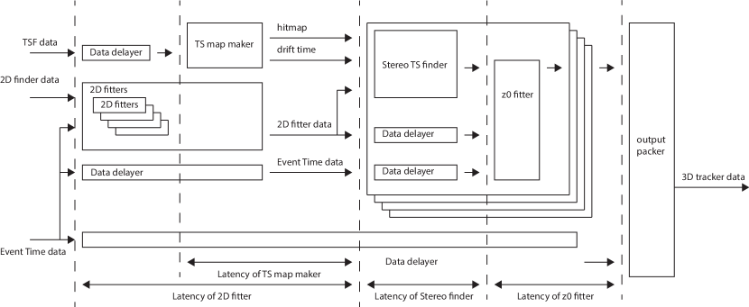
The 3DT consists of multiple modules where the main modules are the TS map maker, stereo TS finder and fitter which can be seen in Fig. 1. The TS map maker integrates the TSF data over a certain amount of time and creates an array of data which we call TS map. The stereo TS finder relates stereo TSs with the tracks that the 2DF finds. The fitter transforms the stereo TS data into a geometrical representation and applies linear regression to fit and .
II.1 TS map maker
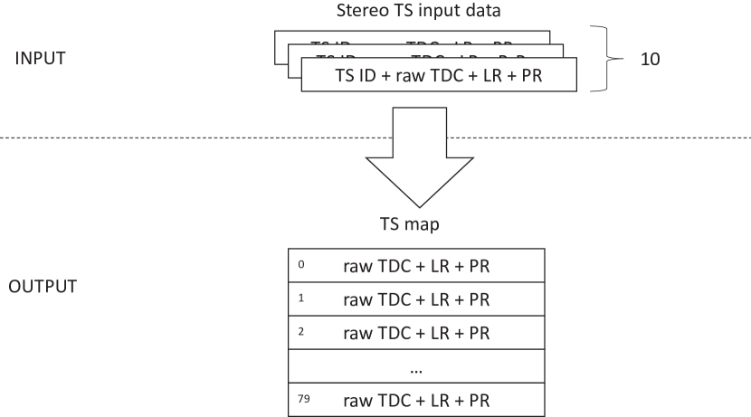
Since the drift time for the CDC can be over than 500 ns, the TSF data that changes every 32 ns should be stored and combined for a certain amount of time. The TSF data consists of 10 TS information for each 32 ns interval. This information is transformed to an array of TS information where the index is the TS ID which we call TS map. The structure of the input TSs and output TS map can be seen in Fig. 2. The TS map is then sent to a module which stores and combines the TS information. When new TS information for a certain index enters the module, a counter which counts how long the TS information has been saved is reset. When the counter reaches a certain amount of time, the TS information is erased.
Four stereo TSF data which cover half of the CDC enter the 3DT, so that there are four of these TS map makers. Each TSF has a different number of possible TS IDs, which are 80, 112, 144, and 176, so that the number of indices of the TS maps follow these numbers.
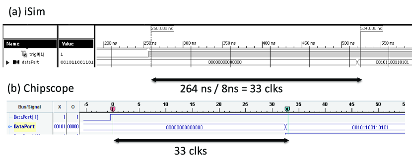
A VHDL VHDL testbench was developed to test the developed firmware for the TS map maker. It was shown that the TS map maker works well as can be seen in Fig. 3. The ISim ISim results and firmware results recorded with Chipscope Chipscope were compared. The timing and values of the results were found to be the same.
II.2 Stereo TS finder

After a track is found by the 2DF, related stereo TSs should be found. By using the two dimensional track information, the geometrically possible stereo TSs are calculated where a framework that automatically generates VHDL was used for development VHDLAutomatic . Between the hit TSs for the possible TSs, the TS which is near the middle is selected. The flow of the logic can be seen in Fig. 4.
To calculate the geometrically possible stereo TSs, the location where the track would pass if the stereo SL was an axial SL is calculated. This location is calculated using the following equation according to the sign of the electric charge,
where the radius of the CDC wire layer is and the curvature and incident angle of the found track are and . This calculated phi location is transformed to the according TS ID by multiplying a constant which depends on the SL. Since the geometrically possible stereo TSs should be within ten TSs from the ID calculated above, an array of 10 TSs is made. Between the hit TSs in the array, the TS which corresponds to the closest point to the IP is selected.
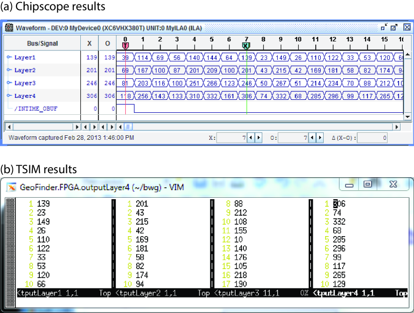
The firmware was tested with a VHDL testbench where data was generated from trigger simulation (TSIM). The results between TSIM and the firmware output recorded with Chipscope were found to be exactly the same for the stereo TS finder in each SL which can be seen in Fig. 5.
II.3 fitter
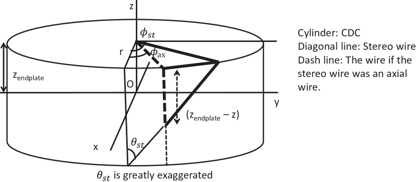
The related stereo TS information is transformed to a geometric representation and then fitted to get track parameters. We first find TDC for each stereo TS by subtracting the “raw” TDC of each stereo TS with “raw” event time. The TDC is converted to a length dimension which we call drift length using a look-up table that has the x-t curve of the CDC. Using the LR information from the TSF, the drift length is added or subtracted to the TS phi position which we call fine phi position. Using two dimensional track parameters and related stereo TS fine phi positions, the location for each stereo TS is calculated with the following equation,
where is the distance from the IP to the end plate of the CDC, is the angle of the stereo wires, and is the fine phi position the stereo TS. The geometric representation of this equation can be seen in Fig. 6. The arc length of the track in the two dimensional () plane for the radius of each stereo SL is calculated with the following equation,
where is the arc length. The track of charge particles in an uniform magnetic field is a helix, so that the two dimensional arc length and of stereo TSs should have a linear relationship. We construct a as below to fit the and using the geometric representation of the stereo TSs,
where is the error of . The and which minimize the can be found analytically as below
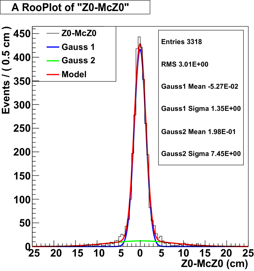
The algorithm was developed using a framework that automatically generates VHDL and validated using TSIM. The resolution of was found to be 1.35 cm which can be seen in Fig. 7. A VHDL testbench was developed for the firmware. The firmware output and TSIM were found to be exactly the same VHDLAutomatic .
III CONCLUSIONS
We have developed firmware that extracts track parameters from the input of the 3DT. The logic we developed that stores the input, finds related TS to a track, transforms the stereo TS to geometric representations, and does linear regression has been shown. Using the extracted track parameters, beam induced backgrounds which do not originate near the IP can be effectively rejected.
Acknowledgments
J. B. acknowledges support from the National Research Foundation of Korean Grants No. 2016K1A3A7A09005587. We thank Korea Institute of Science and Technology Information network group for KREONET network support.
References
- (1) T. Abe et al., arXiv:1011.0352v1.
- (2) Masanori Yamauchi, Nuclear Physics B - Proceedings Supplements, 111, 96 (2002).
- (3) Y. Iwasaki, B. Cheon, E. Won, and G. Varner, IEEE Transactions on Nuclear Science, 58, 1807 (2011).
- (4) N. Taniguchi, Journal of Instrumentation, 12, June (2017).
- (5) J. G. Shiu, in Proceedings of IEEE-NPSS Real Time Conference (Padua, Italy, June 5-10, 2016).
- (6) S. Neuhaus et al. J. Phys., 608, 012052 (2015).
- (7) Duda, R. O. and P. E. Hart, Communications of the ACM, 15, 11 (1972).
- (8) IEEE Computer Society, http://ieeexplore.ieee.org/servlet/opac?punumber=4772738.
- (9) Xilinx, https://www.xilinx.com/support/documentation/sw_manuals/xilinx11/plugin_ism.pdf.
- (10) Xilinx, https://www.xilinx.com/support/documentation/sw_manuals/xilinx14_7/chipscope_pro_sw_cores_ug029.pdf.
- (11) J. B. Kim and E.Won, arXiv:1710.09235.