Experimental observation of topologically protected helical edge modes in Kagome elastic plates
††preprint: Submitted to Nature PhysicsThe investigation of topologically protected waves in classical mediaHuber_NatPhys_2016 has opened unique opportunities to achieve exotic properties like one-way phonon transport He_NatPhys_2016 , protection from backscattering and immunity to imperfections Mousavi_Nat_Comm_2015 . Contrary to acoustic yang2015topological and electromagnetic lu2014topological domains, their observation in elastic solids has so far been elusive due to the presence of both shear and longitudinal modes and their modal conversion at interfaces and free surfaces. Here we report the experimental observation of topologically protected helical edge waves in elastic media. The considered structure consists of an elastic plate patterned according to a Kagome architecture with an accidental degeneracy of two Dirac cones induced by drilling through holes. The careful breaking of symmetries couples the corresponding elastic modes which effectively emulates spin orbital coupling in the quantum spin Hall effect kane2005quantum ; hasan2010colloquium . The results shed light on the topological properties of the proposed plate waveguide and opens avenues for the practical realization of compact, passive and cost-effective elastic topological waveguides.
Two broad ways to achieve topologically protected waveguides in phononic medi susstrunk2016classification include active systems, capable of breaking the time-reversal () symmetry and mimicking the quantum Hall effect Khanikaev_NatComm_2015 ; Wang_PRL_2015 ; Salerno_PRB_2016 ; Swintek_JAP_2015 ; Fleury_Science_2014 ; Nash_PNAS_2015 , and systems comprising solely of passive components assembled to establish analogues to the quantum spin Hall effect (QSHE) Susstrunk_Science_2015 ; Ningyuan_PRX_2015 ; Pal_NJP_2017 ; pal2016helical ; Salerno_NJP_2017 ; brendel2017pseudomagnetic . Key to the latter analogy is the nucleation of a double Dirac cone and the coupling of two degenerate modes corresponding to distinct irreducible representations of the reciprocal lattice symmetry group characterized by a Dirac dispersionMousavi_Nat_Comm_2015 . Thus, systems with multiple degrees of freedom allow multiple possibilities for emulating the QSHE. Elastic plates and their wave mechanics emerge as excellent candidates due to the presence of an infinite number of modes with distinct polarizations and coupled deformation mechanisms. However, although this physics is attractive in terms of quest for topological phases, the following challenges arise: (i) in three dimensional solid structures, only shear and longitudinal modes exist and the dispersion behaviour is linear. Introducing geometrical modifications, either by reducing a dimension to get a plate or by introducing periodic holes and inclusions in the solid, multiple effective modes (Lamb waves, flexural, torsional waves) with intricate mode shapes and nonlinear dispersion branches are induced; (ii) the geometry gets complex as the dispersion bands are tailored to achieve specific wave phenomena and multiple modes exist at any frequency posing problems for opening an isolated band gap; (iii) strong backscattering and mode conversion is promoted at both free boundaries (voids) and interface between distinct materials (inclusions) by the large contrast in acoustic impedance. These challenges have limited the investigations of topological properties of elastic systems, which have been so far restricted to mechanical lattices of coupled rigid bodies Susstrunk_Science_2015 , acoustic metamaterials with resonators governed by scalar equations lu2017observation , and to the analysis of Valley modes for flexural waves in plates Vila_ArXiv_Maggio_2017 .
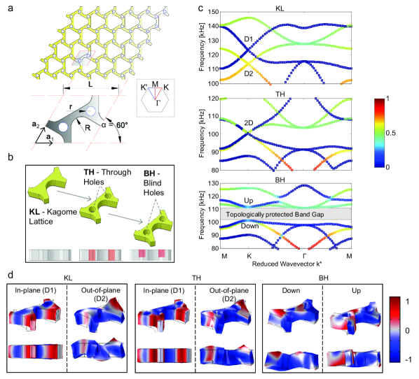
Here we report an analogue of the QSHE in elastic plates. The first step in our process is to design a patterning on the plate such that the resulting periodic media band structure has two overlapping Dirac cones. The second step is to open a topological band gap Susstrunk_Science_2015 ; pal2016helical by carefully breaking the relevant symmetries. In contrast to valley modes where the two sets of modes come from two opposite (, ) valleys, here we work with two distinct sets of modes at each of the high symmetry points. To nucleate a double Dirac cone, we consider an elastic plate patterned according to a Kagome lattice (KL) - Figs. 1a,b, since its band structure exhibits two distinct Dirac points (denoted as and in the top panel of Fig. 1c). A similar configuration was recently investigated in a dual-scale phononic slab Mousavi_Nat_Comm_2015 to achieve a double Dirac point. However this multi-scale approach drastically increased the engineering complexity due to a deep sub-wavelength patterning resulting in the bulk solid having a hexagonal ( symmetry) and thus yielding extreme elastic anisotropy. Here instead, we propose to work solely with isotropic bulk solids and selectively control specific dispersion branches by exploiting their sensitivity to geometric changes within the unit cell. We show how circular through the thickness holes (TH) arranged in a triangular fashion Lu_PRB_2014 (Fig. 1a,b) allow tailoring of the dispersion branches to obtain an isolated double Dirac point (named 2D in the middle panel of Fig. 1c). Finally, blind holes (BH) through part of the thickness of the plate breaks the symmetry, while preserving the symmetry to achieve coupling between the modes spanning the Dirac points, thereby emulating the spin orbital interaction in the QSHE kane2005quantum ; hasan2010colloquium .
The dynamic response of the lattice is governed by the elastic equilibrium equation with being the density, the displacement vector field and the Lamé constants. In the dispersion diagrams shown in Fig. 1c, colors indicate different mode polarization, ranging from pure in-plane (blue), to pure out-of-plane (red) Miniaci_PRL_2017 - see Methods for metrics details. Note that both the Dirac points in the top panel of Fig. 1c correspond to essential degeneracies arising from the lattice having symmetry. An examination of the mode shapes (left panel of Fig. 1d) reveals that the D1 and D2 modes span the subspaces associated respectively with the and irreducible representations dresselhaus2007group of the reciprocal lattice group of wave vector at the point. Furthermore, the mode shapes reveal that D1 and D2 are characterized by dissimilar displacement distributions. This implies that geometric modifications preserving lattice symmetry, such as circular holes through the plate thickness (see TH geometry in Fig. 1b), will preserve the Dirac points, but produce different shifts in their frequency values. This simple approach allows to selectively shift the curves until the nucleation of a four-fold degeneracy with two overlaid Dirac cones (point 2D in the middle panel of Fig. 1c) is obtained (middle panel of Fig. 1c). Here, the double Dirac cone is achieved as an accidental degeneracy huang2011dirac ; chen2014accidental by introducing through holes of radius , with mm being the lattice parameter (see Methods and supplemental material - SM - for mechanical and geometrical details).
Breaking the degeneracy at and coupling the D1 and D2 modes opens a topological band gap (low panel of Fig. 1c). Indeed, in contrast to through holes, which preserve the symmetry without the occurrence of mode coupling, blind holes (BH geometry in Fig. 1b) couple the in-plane (D1) and out-of-plane (D2) modes, activating a mode hybridization process (Fig. 1d, right panel). Breaking the symmetry of the lattice lifts the degeneracy of both the D1 () and D2 () modes. The hole depth which results in the accidental degeneracy between the two sets of separated modes is , where is the plate thickness. This geometrical transformation converts the four-fold degeneracy into a -width non-trivial topologically protected band gap (lower panel of Fig. 1c). As the filled fraction in the hole decreases, the hybridization becomes stronger while the band gap becomes smaller (see SM). In addition, the absence of other modes at nearby frequencies, guarantees an isolated state for the hybridized modes. When two lattices with unit cells, related by transformation, are joined together, topologically protected helical modes exist at the domain wall formed by the shared interface. Their existence is a consequence of the bulk boundary correspondence principle hasan2010colloquium , as the hybridized bulk modes on either side are distinct and related by a transformation. In contrast, at the free boundary, these localized modes hybridize, become defect modes and do not span the bulk band gap Mousavi_Nat_Comm_2015 .
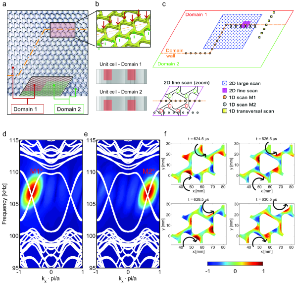
To confirm the emergence of topologically protected helical edge modes, we manufactured and investigated a plate with a Z-shape interface separating two domains with reversed blind holes (dotted orange line in Figs. 2a,b). The Z-path is chosen to show the lack of back-scattering in the presence of sharp corners. A zoom of the domain wall and the arrangement of the reversed unit cells on the full specimen (made of 20 33 unit cells), divided into domain 1 (in red) and domain 2 (in green) are shown as well.
The dispersion curves calculated along a periodic strip illustrate that the system exhibits a pair of helical edge modes (Figs. 2d,e) counter-propagating at the interface. The specimen shows an excellent transmission inside the gap (energy spots in Figs. 2d,e) due to edge modes hosted at the interface. They are labelled M1 and M2, depending on their phase having an anticlockwise or clockwise polarization.
The frequency-wave number representation shown in Figs. 2d,e presents data for the normalized wave number from to and clearly identify the presence of the edge modes inside the gap, confirmed by the experimental energy distribution. The excitation frequency content inside the band gap is intentionally chosen to prevent bulk modes excitation. The two modes have been selectively detected by pointing the laser along specific 1D line scans of the unit cells composing the domain wall (see “1D scan line M1” and “1D scan line M2” in Fig. 2c). Numerically predicted dispersion curves (the white lines) are superimposed onto the experimental data (obtained by plotting the maximum of the 2D-FFT of the acquired signals). An excellent agreement is found. Blue and red colours indicate the minimum and maximum Fourier amplitude. See Methods and SM for details.
To gain insight into the physics of these coupled modes, a fine scan ( mm) on 4 unit cells is performed to experimentally reconstruct the full wavefield occurring during the propagation of the right-propagating edge mode, as presented in Fig. 2f (see the movie in the SM). Colours, varying from blue to red, indicate the out-of-plane displacement of the plate with respect to the unaltered configuration, respectively. The scan clearly shows the presence of both modes with vortex profiles. The black arrows indicate an anticlockwise or clockwise polarization associated with the phase of the displacement field. The vortex chirality can be viewed as a pseudo-spin analogous to the A-B sub-lattice or the top-bottom layer pseudo-spin in graphene systems xiao2007valley . The deformation mechanisms highlight how the system possesses invariant vortex cores with opposite chirality, as required by time-reversal symmetry which is indeed preserved in this approach. In contrast to the so far observed edge modes in acoustic/electromagnetic systems, where shear waves are not supported, here the information concerning the opposite chirality is brought by the out-of-plate thickness, which plays a key role in the reverse propagation process (Fig. 2f).
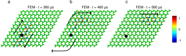
Finally, to verify the phenomenon of negligible backscattering in monolithic elastic waveguides, even in presence of a sharp bend () of the interface, a full 3D transient wave propagation event is first simulated and then experimentally measured on the manufactured structure. Fig. 3 reports a map of the numerically predicted out-of-plane displacement distribution consequent to the excitation of elastic guided waves at the center of the structure (black dot) with a frequency content falling inside the bulk band gap. Wave-fields reconstructed before, while and after the edge mode is traversing the bend, i.e. after s, s and s, respectively, clearly demonstrate how the proposed approach allows a change in the direction of wave propagation (black arrows) without establishing standing wave patterns, typical of trivial waveguides. Besides the lack of backscattering, a weak penetration inside the bulk region is also noticeable.
The experimental full wavefield reconstruction by means of a scanning laser Doppler vibrometer in the top bend of the structure (similar physics is found in the lower bend) confirms the above presented picture. Indeed, the measured out-of-plane velocity distribution detected within the region labelled “2D large scan” in Fig. 2c, is in excellent agreement with the numerical predictions and clearly experimentally illustrates the topologically protected transportation properties of the proposed device. In both the simulations and experiments, the excitation frequency content was intentionally centred inside the bulk band gap to minimize the excitation of bulk modes. This also allowed to quantitatively identify the exponential decay of the field amplitude away from the interface by scanning the deformation field along a straight line transversal to the domain wall (Fig. 2c). Plotting the maximum values of the 2D-FFT of the acquired signals allows to show the decaying path of the wave as a function of the frequency and the distance from the interface (left panel of Fig. 4d), revealing its insensitivity to the frequency of excitation (right panel of Fig. 4d, showing the mentioned decaying profile at 106 kHz).
Figs. 4e shows the comparison of the energy content as a function of the frequency for the M1+ mode before and after the sharp bend. A direct comparison is made possible because pointing the laser exactly along the domain wall ensures that we follow the evolution of a single mode, thereby allowing a quantitative evaluation of backscattering. Fig. 4e, obtained by 2D Fast Fourier transforming the data acquired along two 1D-line scans of the same length token before and after the bend, illustrates the insensitivity of bending around corners on the interface energy transport. In addition, Fig. 4f provides the transmission coefficient. It quantitatively proves that the change in the direction of the wave propagation (before/after bending) does not produce any significant energy lost, unambiguously proving that no mode conversion occurs at the bend, i.e. the left-propagation mode is inhibited.
The results presented in this Letter clearly provide an experimental demonstration of topological robustness and the ability to guide waves along channels with sharp corners in elastic structures. Our design principle and measurement techniques, providing insights on the mechanism of band control to surpass the limits of conventional elastic waveguides, can be extended to explore waveguiding along arbitrary shaped pathways. The results may open up new avenues ma2016acoustic in fields where vibrations play a crucial role, such as civil engineering and the aerospace industry.
References
References
- (1) Huber, S. Topological mechanics, Nat. Phyis. 12, 621 (2016).
- (2) He, C. et al. Acoustic topological insulator and roboust one-way sound transport, Nat. Phyis. 12, 3867 (2016).
- (3) Mousavi, S. H., Khanikaev, A. B. & Wang, Z. Topologically protected elastic waves in phononic metamaterials, Nat. Comm. 6, 8682 (2015).
- (4) Yang, Z. et al. Topological acoustics. Phys. Rev. Lett., 114, 11, 114301 (2015) .
- (5) Lu, L. et al. Topological photonics. Nat. Phot., 8, 11, 821-829 (2014) .
- (6) Kane, C. L. and Mele, E. J. Quantum spin Hall effect in graphene. Phys. Rev. Lett., 95, 22, 226801 (2005).
- (7) Hasan, M. Z. and Kane, C. L. Colloquium: topological insulators Rev. Mod. Phys., 82, 4, 3045 (2010).
- (8) Süsstrunk, R. and Huber, S. D. Classification of topological phonons in linear mechanical metamaterials. Proc. Natl. Acad. Sci. USA, 113, 33, E4767–E4775 (2016).
- (9) Khanikaev, A. B., Fleury, R., Mousavi, S. H. & Alù. A. Topologically robust sound propagation in an angular-momentum-biased graphene-like resonator lattice, Nat. Comm. 6, 8260 (2015).
- (10) Wang, P., Lu, L. & Bertoldi, K. Topological Phononic crystals with one-way elastic edge waves. Phys. Rev. Lett. 115, 104302 (2015).
- (11) Fleury, R., Sounas, D. L., Sieck, C. F., Haberman, M. R. & Alù, A. Topological Phononic crystals with one-way elastic edge waves. Phys. Rev. Lett. 115, 104302 (2015).
- (12) Swinteck, N. et al. Bulk elastic waves with unidirectional backscattering-immune topological states in a time-dependent superlattice J. Appl. Phys., 118, 063103 (2015).
- (13) Nash, L. M. et al. Topological mechanics of gyroscopic metamaterials. Proc. Natl. Acad. Sci. USA, 112, 47 (2015).
- (14) Salerno, G., Ozawa, T., Price, H. M., & Carusotto, I. Floquet topological system based on frequency-modulated classical coupled harmonic oscillators. Phys. Rev. B, 93, 085105 (2016).
- (15) Süsstrunk, R. & Huber, S. Observation of phononic helical edge states in a mechanical topological insulator Science, 349, 47 (2015).
- (16) Ningyuan, J., Owens, C., Sommer, A., Schuster, D. & Simon, J. Time- and site-resolved dynamics in a topological circuit. Phys. Rev. X, 5, 021031 (2015).
- (17) Pal, R. & Ruzzene, M. Edge waves in plates with resonators: an elastic analogue of the quantum valley Hall effect. New J. Phys., 19, 025001 (2017).
- (18) Salerno et al. Spin-orbit coupling in a hexagonal ring of pendula. New J. Phys., 19, 055001 (2017).
- (19) Pal, R. K., Schaeffer, M. & Ruzzene, M. Helical edge states and topological phase transitions in phononic systems using bi-layered lattices. J. Appl. Phys., 119, 8, 084305 (2017).
- (20) Brendel, C. et al. Pseudomagnetic fields for sound at the nanoscale. Proc. Natl. Acad. Sci. USA, 114, 17, E3390–E3395 (2017).
- (21) Lu, J. et al. Observation of topological valley transport of sound in sonic crystals. Nat. Phys., 13, 4, 369-374 (2017).
- (22) Vila, J., Pal, R. K. & Ruzzene, M. Observation of topological valley modes in an elastic hexagonal lattice. ArXiv:1705.08247v1 (2017).
- (23) Lu, J. et al. Dirac cones in two-dimensional artificial crystals for classical waves. Phys. Rev. B, 89, 134302 (2014).
- (24) Miniaci, M. et al Proof of Concept for an Ultrasensitive Technique to Detect and Localize Sources of Elastic Nonlinearity Using Phononic Crystals. Phys. Rev. Lett., 118, 214301 (2017).
- (25) Dresselhaus, M. S. et al. Group theory: application to the physics of condensed matter. Springer (2007).
- (26) Chen, Z. G. et al. Accidental degeneracy of double Dirac cones in a phononic crystal. Sci. Rep., 4, 2014.
- (27) Huang, X. et al. Dirac cones induced by accidental degeneracy in photonic crystals and zero-refractive-index materials. Nat. Mater., 10, 8, 582 (2011).
- (28) Xiao, D. et al. Valley-contrasting physics in graphene: magnetic moment and topological transport. Phys. Rev. Lett., 99 (23), 23689 (2007).
- (29) Ma, G. and Sheng, P. Acoustic metamaterials: From local resonances to broad horizons. Science Advances, 2, 2, e1501595 (2016).
- (30) Miniaci, M., Marzani, A., Testoni, N. & De Marchi, L. Complete band gaps in a polyvinyl chloride (PVC) phononic plate with cross-like holes: numerical design and experimental verification. Ultrasonics, 56, 369-374 (2014).
Acknowledgements
M.M. has received funding from the European Union’s Horizon 2020 research and innovation programme under the Marie Skłodowska-Curie grant agreement N. 658483. M. M. is also grateful to Dr. M. Mazzotti & V. Pagneux for the insightful discussions.
Author contribution
All the authors contributed extensively to the work presented in this paper.
Additional information
Supplemental information is available in the online version of the paper. Correspondence and requests for material should be addressed to M.R. or M.M.
Competing financial interests
The authors declare no competing financial interests.
Methods
Simulations. Dispersion diagrams and mode shapes presented in Figs. 1 and 2 are computed using Bloch-Floquet theory in full 3D FEM simulations carried out via the finite-element solver COMSOL Multiphysics. Full 3D models are implemented to capture all the possible wave modes. Linear elastic constitutive law is adopted and the following mechanical parameters for the waveguide considered: density , Young modulus GPa, and Poisson ratio . Cells are meshed by means of 4-node tetrahedral elements of maximum size mm in order to provide accurate eigensolutions up to the maximum frequency of interest Miniaci_Ultrasonics_2014 . The band structures are derived assuming periodic (along the lattice vector and directions - see Fig. 1a) and free (in the out-of-plane direction) boundary conditions at the edges of the cell domains for all the cases considered in Fig. 1a. Dispersion diagrams shown in Fig. 2 are computed instead considering -periodic strips. The resulting eigenvalue problem is solved by varying the wavevector values along the boundary of the irreducible Brillouin zone , with , and for dispersion diagrams in Fig. 1b and from to for band structures presented in Fig. 2. Colours in Fig. 1b indicate the mode polarization which is calculated defining a polarization factor , where is the volume of the unit cell, , and are the displacement components along , and axes, respectively Miniaci_PRL_2017 . The dispersion curves are shaded accordingly, with colours varying from (blue) to (red), making the colour change from blue to red gradually. Thus colours close to red indicate vibration modes that are dominantly polarized out-of-plane, while the colours close to blue are predominantly polarized in-plane. The numerical wave-field reconstruction is performed via full 3D finite-element transient dynamic analysis in ABAQUS, where the experimental specimen geometry is accurately reproduced.
Experimental measurements. The topologically protected waveguide is fabricated through a two step machining process. First, the simple Kagome lattice is obtained through waterjet cutting, and then circular holes are drilled via computer assisted drilling process. The waveguide consists of unit cells. The Specimen is made of aluminium 6082 T6, with density , Young modulus GPa, and Poisson ratio . The geometrical parameters are the following: mm, mm, mm, mm, mm.
Elastic waves are excited through a Krautkramer transducer ( cm diameter and MHz central frequency) glued to the top surface of the waveguide and launching ultrasonic pulses made of 51 sine cycles Hanning windowed with a central frequency of kHz. Refer to the SM for further details.
Dispersion curves for the edge modes (Figs. 2d and 2e) are obtained by 2D Fourier transforming the signals detected along the scanning line 1 and 2 reported in Fig. 2c. The specific positions allowed to follow a single mode (M1 or M2). The maximum value of the energy as a function of the wavenumber and frequency is plotted.
The experimental wavefield reconstructions shown in Figs. 2f and 4a-c are obtained by means of scanning laser Doppler vibrometer measurements. The laser has been moved over ad-hoc designed grids due to the geometrical complexity. A step of approximately mm for the fine scan (Fig. 2f) and mm for the larger scan (Fig. 4a-c) have been used.
Figs. 4e,f are obtained by means of a 2D-FFT performed on 1D-line scans of the same length token before and after the Z-bend. This allowed a quantitative evaluation of the lack of backscattering. Refer to the SM for the extended description of the experimental configurations.
In all the experiments no absorbers are placed at the boundaries of the samples to avoid any artificial dynamics alteration or mode conversion prevention during the propagation process.
Data availability. The data that support the plots within this paper and other findings of this study are available from the corresponding author upon request.