Direct detection of the 229Th nuclear
clock transition
Lars von der Wense1,††1Ludwig-Maximilians-University Munich, 85748 Garching, Germany. 2 GSI Helmholtzzentrum für Schwerionenforschung GmbH, 64291 Darmstadt, Germany. 3 Helmholtz Institute Mainz, 55099 Mainz, Germany. 4 Johannes Gutenberg University, 55099 Mainz, Germany. Benedict Seiferle1, Mustapha Laatiaoui2,3, Jürgen B. Neumayr1, Hans-Jörg Maier1, Hans-Friedrich Wirth1, Christoph Mokry3,4, Jörg Runke2,4, Klaus Eberhardt3,4, Christoph E. Düllmann2,3,4, Norbert G. Trautmann4 &
Peter G. Thirolf1
Today’s most precise time and frequency measurements are performed with optical atomic clocks. However, it has been proposed that they could potentially be outperformed by a nuclear clock, which employs a nuclear transition instead of the atomic shell transitions used so far. By today there is only one nuclear state known which could serve for a nuclear clock using currently available technology, which is the isomeric first excited state in 229Th. Here we report the direct detection of this nuclear state, which is a further confirmation of the isomer’s existence and lays the foundation for precise studies of the isomer’s decay parameters. Based on this direct detection the isomeric energy is constrained to lie between 6.3 and 18.3 eV, and the half-life is found to be longer than 60 s for 229mTh2+. More precise determinations appear in reach and will pave the way for the development of a nuclear frequency standard.
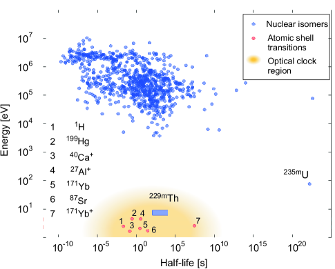
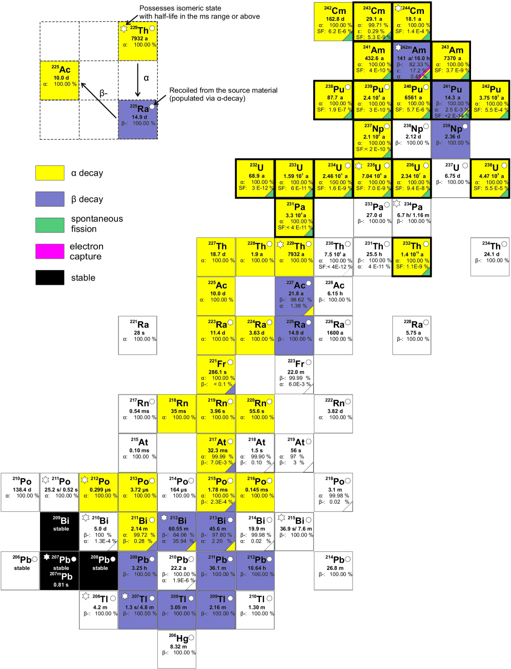
The first excited nuclear state in 229Th is one of the most exotic states in the whole nuclear landscape, as among all presently known 176,000 nuclear levels [1], it possesses the lowest excitation energy of only about eV [2, 3]. While there is just one other nuclear excitation known to have a transition energy below 1 keV [1] (235mU, 76 eV), typical nuclear excitation energies are to times larger [4] (Fig. 1).
The 229Th nucleus was first considered in 1976 by Kroger and Reich to possess an isomer (a metastable nuclear state) with excitation energy below 100 eV [5]. Further measurements supported its existence [6, 7] and led to a stepwise improvement to eV excitation energy in 1994 [8]. However, in 2007 a microcalorimetric measurement suggested a value of eV, corresponding to a wavelength near 160 nm for radiation emitted in the decay to the ground state [2, 3].
This uniquely low nuclear transition energy can potentially bridge the fields of nuclear and atomic physics, as it conceptually allows for optical laser excitation of a nuclear transition [9]. This in turn has stimulated thoughts about transferring existing knowledge of laser manipulation of the electronic shell to a nuclear system, leading to highly interesting applications such as a nuclear laser [10], nuclear quantum optics [11], and a nuclear clock [12].
Besides the low excitation energy, a radiative isomeric half-life in the range of minutes to hours has been predicted [13, 14, 15], resulting in a relative linewidth as low as . These unique features render this transition an ideal candidate for a nuclear clock [12], which may outperform existing atomic-clock technology due to potentially improved compactness and expectedly higher resilience against external influences [16]. Two ways to establish a nuclear clock are currently being investigated; one based on 229Th3+ stored in a Paul trap [17, 18, 19], the other one based on 229Th embedded in a crystal-lattice environment [12, 20, 21, 22, 23].
The immediate impact and far reaching implications of a nuclear clock become clear when considering current applications of existing atomic-clock technology [24]. Moreover, a nuclear clock promises intriguing applications in fundamental physics, e.g., the investigation of possible time variations of fundamental constants [25, 26, 27, 28].
To date, experimental knowledge of the isomer has been inferred indirectly [2, 3, 5, 6, 7, 8]. However, a direct detection was still pending. Such a direct detection would not only give further evidence for the isomer’s existence, but also pave the way for precise studies of the half-life, excitation energy and decay mechanism of the isomeric state, which are the basis for a direct optical excitation [29]. This has motivated significant experimental effort aimed at further validation of the isomer’s existence [30, 31, 32] and direct detection of the isomeric deexcitation [21, 33, 34, 35, 36, 37, 38]. For a detailed overview we refer the reader to the recent review of Peik and Okhapkin and references therein [39]. Despite decade-long efforts, none of these previous attempts has conclusively reported the isomer’s direct detection. We report here on the direct observation of this elusive isomeric decay. This direct detection paves the way for the precise determination of all decay parameters relevant for optical excitation.
Experimental setup
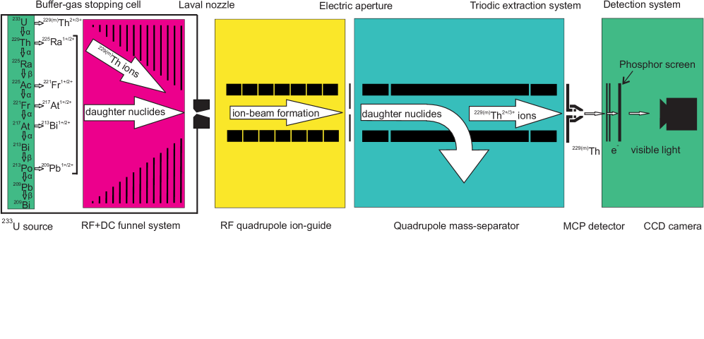
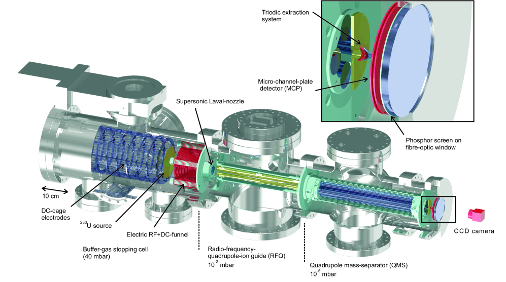
Decay of the 229Th isomeric state in the neutral thorium atom occurs predominantly by internal conversion (IC) under emission of an electron [14, 15], which is used as a key signature for identifying the 229Th isomer (3/2+[631]) to ground state (5/2+[633]) deexcitation. A short half-life in the s range was predicted for this case [14, 15]. This is because the 6.31 eV first ionisation potential of thorium is below the suggested energy of the isomeric transition. In a higher charge state (i.e. thorium ions), the IC process is energetically forbidden and radiative decay may dominate. In this case, the half-life is expected to increase significantly to minutes or hours. While searches for an IC decay with a half-life of a few ms or longer for neutral thorium have already been conducted [40], our experimental setup [41], as shown in Fig. 2, was designed for the detection of a low-energy IC decay of shorter half-life. A schematic of the experimental process is shown in Extended Data Fig. 1.
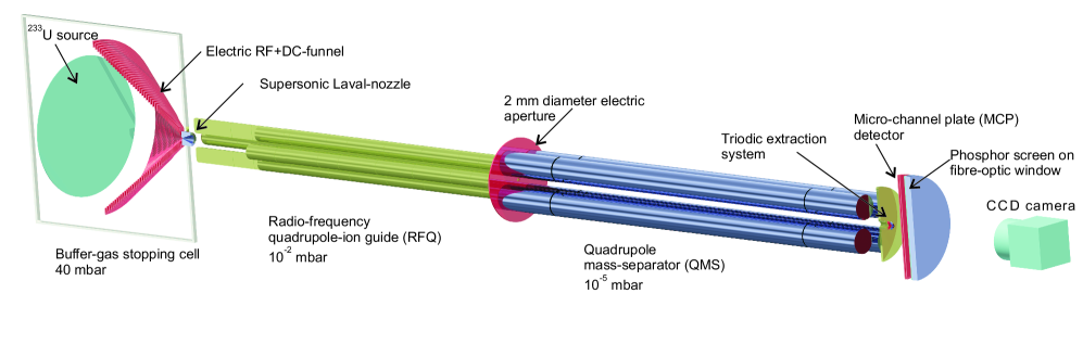
The isomeric state in 229Th can be populated via a 2% decay branch in the decay of 233U [42]. For detection of the isomer, a 233U source is placed in a buffer-gas stopping cell [43] (Extended Data Fig. 2) into which 229Th ions, produced in the decay of 233U, are recoiling, along with 229Th daughter products if present in the source. These -recoil ions are stopped in 40 mbar of ultra-pure helium. Removing the up to 84 keV kinetic recoil-energy (significantly greater than the few eV isomer energy) is essential for the experiment. During the stopping process charge exchange occurs producing predominantly thorium in the 2+ and 3+ charge states. These ions are guided by an electric field through a radio-frequency (RF) and direct-current (DC) funnel system towards the buffer-gas stopping cell exit, where they are extracted by a supersonic Laval-nozzle and injected into a radio-frequency quadrupole (RFQ) structure. While the ions are guided by the electric fields provided by the RFQ, the remaining ambient helium gas pressure leads to phase-space cooling, such that a recoil-ion beam with sub-mm diameter is formed at the RFQ exit. There, most of the daughter nuclides from the 233U decay chain are still present, some of which are short-lived or emitters. A quadrupole mass-separator (QMS) is used for ion-beam purification, such that only 229Th remains. Subsequently, the thorium ions are guided with the help of a triodic guidance structure with a 2-mm diameter orifice towards a micro-channel plate (MCP) detector, used for low-energy electron detection. The ions are collected in soft landing at low kinetic energy (50-75 eV, depending on the charge state) directly on the MCP detector (operated at V surface voltage), which is placed in front of a phosphor screen. The latter is monitored by a charge-coupled device (CCD) camera, allowing for a spatially resolved signal detection.
Isomer detection
Because stopping and extraction of 229Th occurs in the form of ions and takes only a few ms, there is no significant isomer decay during time of flight. However, when the ions come into contact with the MCP surface, charge exchange occurs forming neutral thorium atoms for which the rapid IC expectedly dominates the decay of the isomeric state. This process releases a conversion electron, which is accelerated into a microchannel of the MCP detector, triggering the emission of secondary electrons. The electron ’cloud’ thusly produced is accelerated towards the phosphor screen, where the electronic-impact signal is converted into visible light that is detected with the CCD camera. This detection technique reveals a significant similarity to the MCP-based detection of metastable molecular states in chemistry [44] and has already been successfully applied to the detection of
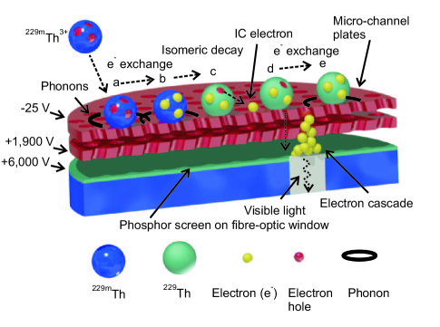
235mU [40]. A schematic drawing of the detection process on the MCP surface from a microscopic perspective is shown in Figure 3 (see also Methods section).
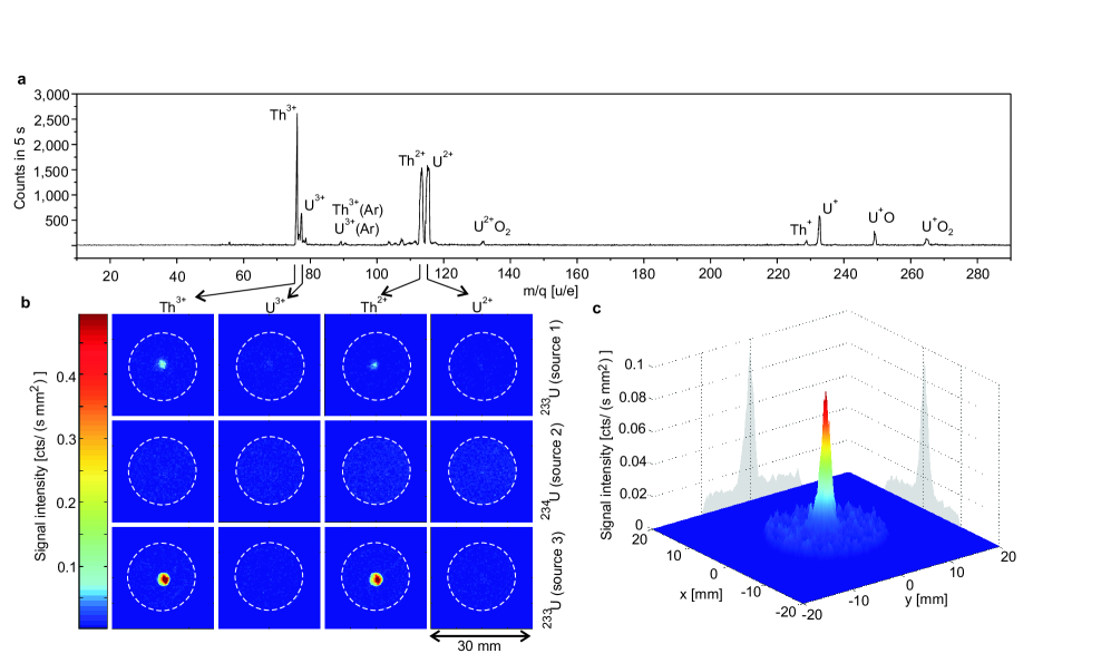
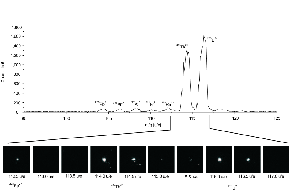
The 233U source (in the following denoted as source 1) consists of a layer of 233UF4 (of activity level kBq) that was evaporated onto a 20-mm diameter stainless steel plate. A complete mass scan of ions extracted from this source is shown in Fig. 4 a. We measured the 229Th3+ ion extraction rate from source 1 to be about s-1 [45]. Assuming that 2% of the ions are in the isomeric state [42] and also accounting for an MCP detection efficiency for low energy electrons of about 1.5% [46], a count rate of cts/s is expected. The isomeric-decay signal as obtained when extracting 229Th3+ for 2,000 s is shown in Fig. 4 c. Signals were acquired within a centered field of view as obtained within a 20-mm diameter aperture (see Methods for details of image readout). The spatially integrated decay count rate is () cts/s and in good agreement with the expectations. The error was estimated to also account for changes in the 229Th3+ extraction efficiency.
The MCP exhibits a low dark count rate of 0.01 cts/s mm2, leading to a signal to background ratio of about 8:1. An overview over different measurements performed under the same conditions is shown in Fig. 4 b. Each row corresponds to an individual uranium source, as will be detailed in the following section, while each column corresponds to a different extracted ion species, as indicated by the arrows from the mass scan. Clear signals are seen when extracting 229Th2+ and 229Th3+, respectively (Fig. 4 b, first row). For completeness, measurements were also performed while extracting 229Th1+. In this case, no signal could be obtained, which might be attributed to the very low extraction efficiency of just 0.3% for Th1+, compared to 5.5% for Th2+ and 10% for Th3+ [45].
Signal identification
In order to prove that the detected signal originates from the 229Th isomeric decay, comparative measurements were performed which allowed us to exclude all potential background sources. These can be grouped into four categories: (A) background attributed to the kinetic energy or charge state of the impinging ions, (B) background signals from setup components (233U source, buffer-gas stopping and extraction, QMS, MCP detection system), (C) signals originating from the thorium atomic shell (long-lived excited states or chemical reactions on the MCP surface) and (D) signals caused by short-lived nuclides or other isomers (not of 229Th). Most of the possible background effects were excluded in several ways. An overview is shown in the Extended Data Table 1, to which the given measurement numbers refer.
Ionic energy, as carried in form of the momentum or ion charge state, may lead to the release of electrons on the MCP surface. In order to exclude this type of background (type A), a 233U2+ mass peak (originating from sputtering of the source), which has a similar intensity as the 229Th2+ mass peak (Fig. 4 a), is used for comparison (Extended Data Table 1 no. 1). Within 2,000 s of continuous extraction of 233U2+ no MCP signal was obtained (Fig. 4 b, first row).
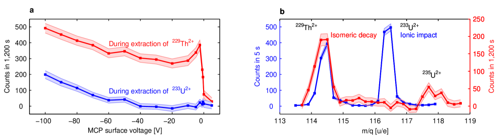
Furthermore, a measurement of the signal intensity as a function of the MCP surface voltage was carried out for 229Th2+ and 233U2+ (Extended Data Table 1 no. 2, Fig. 5 a). For this purpose, each isotope was extracted 1,200 s for every data point. For MCP surface voltages between V and V the remaining ion-impact signal decreases as the kinetic energy of the ions is reduced. While the uranium signal is effectively reduced to zero, a thorium signal remains. A sharp cut-off of this signal occurs at zero kinetic energy, when the ions can no longer approach the MCP surface. An enhancement of the signal intensity is observed close before the cut-off, attributed to IC electrons back-attracted into the MCP surface. The absence of a similar sharp cut-off for uranium clearly excludes any cause of the signal by ion impact or charge state. Further, these measurements also exclude all potential background caused by the setup components (type B), which would be constant throughout the measurements.
Thorium atomic shell effects such as a long-lived atomic excitation or a chemical reaction between thorium and the MCP surface could potentially contribute background (type C). To exclude this possibility it is sufficient to perform a comparative measurement with 230Th where such effects would be identical (Extended Data Table 1 no. 3). For this purpose, a 234U source was employed (270 kBq, electrodeposited onto a titanium sputtered silicon wafer, in the following denoted as source 2). The 230Th -recoil ions emerging from this source were accumulated on the surface of the MCP detector for 2,000 s, just as for 229Th. For 230Th, however, no signal is detected (Fig. 4 b, second row), which proves that the signal obtained for 229Th cannot be caused by an atomic shell effect. This measurement also provides further exclusion of
background of types (A) and (B). In this way most of the systematic background effects are excluded.
In former experiments, direct identification of the 229mTh isomeric decay has been prevented in part by radioactive decay of short-lived daughter nuclides [39]. Our experiments focused specially on this type of potential background (type D), that we have been able to exclude in four independent ways. A quadrupole mass-separator (QMS) is used for the extraction of ions with a well-defined mass-to-charge ratio from the buffer-gas stopping cell. The achieved mass-resolving power of is sufficient for the complete separation of the -recoil ions with a difference of four or more atomic mass units (Extended Data Fig. 3). Figure 5 b shows the signal intensity as a function of the selected mass-to-charge ratio for MCP surface voltages of V and V. At a V surface voltage (blue) the ion-impact signal is observable and the 233U2+ and 229Th2+ mass peaks are of comparable amplitude. At the V surface voltage (red) the 233U2+ mass peak completely vanishes, since no ion-impact signal is detected. 229Th2+, in contrast, reveals a remaining component, which is clearly restricted to the 229Th2+ mass peak. However, molecular sidebands may be populated by nuclides of lower masses (e.g. 213Bi16O reveals the same mass as 229Th and is a emitter in the 233U decay chain with a 45.6 minute half-life). Thus restriction to the value of 229Th2+ does not exclude short-lived daughter nuclides as signal contributions.
One way to exclude this sort of background is obtained from the parallel observation of the signals in the and the charge states (Extended Data Table 1 no. 4, Fig. 4 b, first row), because only thorium is extracted to a significant amount in the charge state due to its low 3rd ionisation potential [45] (see Extended Data Table 2 for comparison). Experimentally, a suppression of three to four orders of magnitude for the short-lived daughters in the charge state compared to the charge state was obtained [45].
One further comparison (Extended Data Table 1 no. 5) was performed with a newly available chemically purified 233U source (source 3, 290 kBq, same geometry as source 2). The factor of chemical purification of the short-lived daughter nuclides was measured to be . In case signals were originating from nuclear background, a drastically reduced signal intensity should occur. This reduction is, however, not observed and instead the signal increases by a factor of due to a larger 233U content and a reduced source thickness, leading to a higher -recoil efficiency (Fig. 4 b, third row).
Two other ways for excluding nuclear background are discussed in the Methods section. Consequently, the nuclear isomeric transition in 229Th is the only possible explanation for the observed signal.
Half-life and energy constraints
Direct detection of the 229mTh isomeric-decay signal provides first constraints on the half-life of the isomer, which is found to be heavily charge-state dependent. Two different
measurements were performed (see Methods for details): the first one conducted to estimate an upper limit for the isomeric half-life in the neutral thorium atom, and the second one conducted to infer a lower limit for the isomer’s lifetime in 229Th2+. These measurements allow to draw conclusions on the isomeric energy, as the half-life changes depending on whether the IC decay channel is energetically permitted or not.
For the neutral thorium atom, 229mTh is predicted to decay predominantly by IC with a half-life as short as microseconds [14, 15]. Experimentally an upper limit for the isomeric half-life in neutral thorium was found by 229(m)Th2+ ion-beam pulsing. Images were acquired directly after the ion-pulse had impacted the MCP surface, leading to the formation of neutral thorium by charge exchange. In this way the half-life was determined to be less than one second, confirming that the isomeric IC decay-channel is energetically allowed. This in turn gives strong indication that the isomeric energy is above the 1st ionisation potential of thorium of 6.31 eV.
An isomeric half-life of minutes to hours has been predicted for 229mTh in a charge state , where IC is energetically forbidden [14, 15]. In order to confirm this prediction, 229(m)Th2+ ions were stored in the RFQ before acquiring the isomeric-decay signal. The half-life range probed in this way was limited by the maximum ion storage time in the RFQ, which is about 60 s. Still, after this time, significant isomeric decay was detected, suggesting the isomeric lifetime in Th2+ to be longer than 60 s. This long half-life can only be explained if the isomeric IC decay-channel is energetically forbidden for 229Th2+. Thus the isomeric energy must be below the 3rd ionisation potential of thorium of 18.3 eV.
Based on the half-life estimates, the value of the isomeric energy is deduced to be between 6.3 and 18.3 eV (i.e. between the 1st and 3rd ionisation potential of thorium). This energy range is consistent with today’s most accepted value [2] and promising for the development of a nuclear clock based on thorium ions.
Discussion and perspectives
The efficient production of a low-energy, highly pure 229(m)Th ion beam enabled the successful direct observation of the 229Th isomer to ground-state decay, via spatially decoupled isomer population and isomeric decay, combined with an efficient mass separation using a QMS.
This measurement is not only a further proof of the isomer’s existence, which has been controversial [29, 47], but also provides a detection method that can be used as a tool to probe different processes for isomer population, e.g., via direct laser excitation [18] or electronic bridge processes [39]. Further, in the nuclear-clock concept the observed IC decay could be used to probe the isomeric population to provide an alternative to the double-resonance method proposed so far [12]. Most importantly, this direct detection paves the way for precise determination of the isomer’s decay parameters. The isomeric half-life can be probed by applying a cryogenically cooled Paul trap [48], which allows for longer ionic storage times. A significantly more precise energy value can be determined by applying a hemispherical electron energy analyser [49] with an energy resolution of a few meV (see Methods for details). This will usher the possibility for developing a laser system that can ultimately bring all-optical control of this nuclear transition and thus provide a template for coherent manipulation of nuclei in general [50]. The construction of a nuclear frequency standard based on this 229Th isomeric transition will enable new perspectives for ultra-precise frequency metrology and is expected to have implications for both technology and fundamental physics.
References
- [1] NNDC Interactive Chart of Nuclides [Online]. Available at http://www.nndc.bnl.gov/chart [2015, June 16]. Brookhaven National Laboratory, Brookhaven.
- [2] Beck, B.R. et al. Energy splitting of the ground-state doublet in the nucleus 229Th. Phys. Rev. Lett. 98, 142501 (2007).
- [3] Beck, B.R. et al. Improved value for the energy splitting of the ground-state doublet in the nucleus 229mTh. LLNL-PROC-415170 (2009).
- [4] Tuli, J.K. Nuclear wallet cards. National Nuclear Data Center, Brookhaven National Laboratory, Brookhaven. 8th edition (2011).
- [5] Kroger, L.A. & Reich, C.W. Features of the low energy level scheme of 229Th as observed in the decay of 233U. Nucl. Phys. A 259, 29-60 (1976).
- [6] Burke, D.G., Garrett, P.E., Qu, T. & Naumann, R.A. Additional evidence for the proposed excited state at 5 eV in 229Th. Phys. Rev. C 42-2 499-501 (1990).
- [7] Burke, D.G., Garrett, P.E., Qu, T. & Naumann, R.A. Nuclear structure of 229,231Th studied with the 230,232Th(d,t) reactions. Nucl. Phys. A 809 129-170 (2008).
- [8] Helmer, R.G. & Reich, C.W. An excited state of 229Th at 3.5 eV. Phys. Rev. C 49, 1845-1859 (1994).
- [9] Tkalya, E.V. Properties of the optical transition in the 229Th nucleus. Phys. Usp. 46, 315-324 (2003).
- [10] Tkalya, E.V. Proposal for a nuclear gamma-ray laser of optical range. Phys. Rev. Lett. A 106, 162501 (2011).
- [11] Bürvenich, T.J., Evers, J. & Keitel, C.H. Nuclear quantum optics with x-ray laser pulses. Phys. Rev. Lett. 96 142501 (2006).
- [12] Peik, E. & Tamm, C. Nuclear laser spectroscopy of the 3.5 eV transition in 229Th. Eur. Phys. Lett. 61, 181-186 (2003).
- [13] Ruchowska, E. et al. Nuclear structure of 229Th. Phys. Rev. C 73, 044326 (2006).
- [14] Karpeshin, F.F. & Trzhaskovskaya, M.B. Impact of the electron environment on the lifetime of the 229Thm low-lying isomer. Phys. Rev C 76, 054313 (2007).
- [15] Tkalya, E.V., Schneider, C., Jeet, J., Hudson, E.R. Radiative lifetime and energy of the low-energy isomeric level in 229Th. Phys. Rev. C 92, 054324 (2015).
- [16] Peik, E., Zimmermann, K., Okhapkin, M. & Tamm, C. Prospects for a nuclear optical frequency standard based on thorium-229. Proceedings of 7th symposium on frequency standards and metrology (5-11 October 2008), 532-538 (2009).
- [17] Zimmermann, K. Experiments towards optical nuclear spectroscopy with Thorium-229. Ph.D. thesis, Univ. Hannover, Germany (2010).
- [18] Campbell, C.J., Radnaev, A.G. & Kuzmich, A., Wigner Crystals of 229Th for optical excitation of the nuclear isomer. Phys. Rev. Lett. 106, 223001 (2011).
- [19] Campbell, C.J. et al. Single-Ion nuclear clock for metrology at the 19th decimal place. Phys. Rev. Lett. 108, 120802 (2012).
- [20] Tkalya, E.V., Zherikhin A.N., Zhudov, V.I. Decay of the low-energy nuclear isomer 229Thm(3/2+, 3.51.0 eV) in solids (dielectrics and metals): A new scheme of experimental research. Phys. Rev. C 61 064308 (2000).
- [21] Jeet, J. et al. Results of a direct search using synchrotron radiation for the low-energy 229Th nuclear isomeric transition. Phys. Rev. Lett. 114, 253001 (2015).
- [22] Kazakov, G.A. et al. Performance of a 229Thorium solid-state nuclear clock. New J. Phys. 14, 083019 (2012).
- [23] Stellmer, S., Schreitl, M. & Schumm, T. Radioluminescence and photoluminescence of Th:CaF2 crystals. Scientific Reports 5, 15580 (2015).
- [24] Nicholson, T.L. et al. Systematic evaluation of an atomic clock at total uncertainty. Nature Communications 6, 6896 (2015).
- [25] Flambaum, V.V. Enhanced effect of temporal variation of the fine structure constant and the strong interaction in 229Th. Phys. Rev. Lett. 97, 092502 (2006).
- [26] Hayes, A.C., Friar, J.L. & Möller, P. Splitting sensitivity of the ground and 7.6 eV isomeric states of 229Th. Phys. Rev. C 78, 024311 (2008).
- [27] Litvinova, E., Feldmeier, H., Dobaczewski & Flambaum, V. Nuclear structure of lowest 229Th states and time-dependent fundamental constants. Phys. Rev. C 79, 064303 (2009).
- [28] Rellergert, W.G. et al. Constraining the evolution of the fundamental constants with a solid-state optical frequency reference based on the 229Th nucleus. Phys. Rev. Lett. 104, 200802 (2010).
- [29] Matinyan, S. Lasers as a bridge between atomic and nuclear physics. Phys. Rep. 298, 199-249 (1998).
- [30] Raeder, S. et al. Resonance ionization spectroscopy of thorium isotopes-towards a laser spectroscopic identification of the low-lying 7.6 eV isomer of 229Th. J. Phys. B 44, 165005 (2011).
- [31] V. Sonnenschein, Raeder, S., Hakimi, A., Moore, I.D. & Wendt, K. The search for the existence of 229mTh at IGISOL. Eur. Phys. J. A 48, 52 (2012).
- [32] Kazakov, G.A. et al. Prospects for measuring the 229Th isomer energy using a metallic magnetic microcalorimeter. Nucl. Instrum. Methods A 735, 229-239 (2014).
- [33] Irwin, G.M. & Kim, K.H. Observation of electromagnetic radiation from deexcitation of the 229Th isomer. Phys. Rev. Lett. 79-6, 990-993 (1997).
- [34] Richardson, D.S., Benton, D.M., Evans, D.E., Griffith, J.A.R. & Tungate, G. Ultraviolet photon emission observed in the search for the decay of the 229Th isomer. Phys. Rev. Lett. 80-15, 3206-3208 (1998).
- [35] Utter, S.B.et al. Reexamination of the optical gamma ray decay in 229Th Phys. Rev. Lett. 82-3, 505-508 (1999).
- [36] Zhao, X. et al. Observation of the deexcitation of the 229mTh nuclear isomer. Phys. Rev. Lett. 109, 160801 (2012).
- [37] Peik, E. & Zimmermann, K. Comment on "Observation of the deexcitation of the 229mTh nuclear isomer". Phys. Rev. Lett. 111, 018901 (2013).
- [38] Yamaguchi, A. et al. Experimental search for the low-energy nuclear transition in 229Th with undulator radiation. New J. Phys. 17, 053053 (2015).
- [39] Peik, E. & Okhapkin, M. Nuclear clocks based on resonant excitation of -transitions, C.R. Physique 16, 516-523 (2015).
- [40] Swanberg, E. Searching for the decay of 229mTh. Ph.D. thesis, University of California, Berkeley (2012).
- [41] v.d.Wense, L., Thirolf, P.G., Kalb, D. & Laatiaoui, M. Towards a direct transition energy measurement of the lowest nuclear excitation in 229Th. JINST 8, P03005 (2013).
- [42] Barci, V., Ardisson, G., Barci-Funel, G., Weiss, B. & El Samad, O. Nuclear Structure of 229Th from -ray spectroscopy study of 233U -particle decay. Phys. Rev. C 68, 034329 (2003).
- [43] Neumayr, J.B. et al. Performance of the MLL-Ion Catcher. Rev. Sci. Instr. 77, 065109 (2006).
- [44] Jongma, R.T., Rasing, T. & Meijer, G. Two-dimensional imaging of metastable CO molecules. J. Chem. Phys. 102-5, 1925-1933 (1995).
- [45] v.d.Wense, L., Seiferle, B., Laatiaoui, M. & Thirolf, P.G. Determination of the extraction efficiency for 233U source -recoil ions from the MLL buffer-gas stopping cell. Eur. Phys. J. A 51, 29 (2015).
- [46] Goruganthu, R.R. & Wilson, W.G. Relative electron detection efficiency of microchannel plates from 0-3 keV. Rev. Sci. Instrum. 55, 2030-2033 (1984).
- [47] Sakharov, S.L. On the energy of the 3.5 eV level in 229Th. Phys. At. Nucl. 73, 1-8 (2010).
- [48] Schwarz, M. et al. Cryogenic linear paul trap for cold highly charged ion experiments. Rev. Sci. Instrum. 83, 083115 (2012).
- [49] Martensson, N. et al. A very high resolution electron spectrometer. J. Electron Spectrosc. 70, 117-128 (1994).
- [50] Liao, W.T., Pálffy, A. & Keitel, C.H. Nuclear coherent population transfer with x-ray laser pulses. Phys. Lett. B 705, 134-138 (2011).
Acknowledgements We acknowledge fruitful discussions with D. Habs, T.W. Hänsch, T. Udem, T. Lamour, J. Weitenberg, A. Ozawa, E. Peters, J. Schreiber, P. Hilz, T. Schumm, S. Stellmer, F. Allegretti, P. Feulner, J. Crespo, M. Schwarz, L. Schmöger, P. Micke, C. Weber, P. Bolton and K. Parodi. We thank T. Lauer for the Ti-sputtering of the Si-wafers and the MPQ for the temporary loan of the MCP detector. We thank I. Cortrie L. Black and J. Soll for graphic design support. This work was supported by DFG (Th956/3-1) and by the European Union’s Horizon 2020 research and innovation programme under grant agreement No 664732 "nuClock".
Author Contributions L.v.d.W., B.S. and P.G.T. performed the experiments. M.L. and J.B.N. did preparatory experimental work. H.-J.M. and H.-F.W. produced the radioactive source 1. C.M., J.R., K.E., C.E.D., N.G.T. and L.v.d.W. produced the radioactive sources 2 and 3. L.v.d.W., P.G.T. and B.S. wrote the manuscript with input from all authors.
Author Information Reprints and permissions information is available at www.nature.com/reprints. The authors declare no competing financial interests. Readers are welcome to comment on the online version of the paper. Correspondence and requests for materials should be addressed to L.v.d.W.(L.Wense@physik.uni-muenchen.de).
Methods
233U and 234U -recoil ion sources. Three different sources were employed in these experiments. Source 1 consists of about 200 kBq 233U (UF4), evaporated in vacuum from a tantalum heater lined with a vitreous carbon crucible [1] onto a 20-mm diameter stainless-steel plate. The preparation was performed in the former hot-lab facility of the LMU Munich [2]. The UF4-layer thickness is (36020) nm, leading to a recoil efficiency of about 5.3% for 229Th. The source material was not chemically purified before evaporation. As the material was produced around 1969, a significant ingrowth of short-lived daughter nuclides occurred since then. An unavoidable fraction of 232U contamination was determined by spectroscopy to at the time of material production [45].
Source 2 consists of () kBq 234U, deposited by molecular plating [3] onto the surface of a Ti-sputtered Si-wafer of 100 mm diameter. It has a thickness of 0.5 mm with a 100 nm thick layer of sputtered titanium. The active surface area of the source is 90 mm in diameter, leaving a 12 mm diameter unplated region in the center.
Source 3 is a newly available 233U source of about 290 kBq. Just like source 2, it was deposited by molecular plating with 90 mm diameter onto the surface of a Ti-sputtered Si-wafer of 100 mm diameter. Due to the smaller source thickness, the thorium extraction rate was improved by a factor of about 13.5 compared to source 1. The source 3 material was chemically purified before deposition by ion-exchange chromatography to remove the 233U and 232U daughter nuclides. A relative purification factor of was found, based on a comparison of -energy spectra of the source material before and after chemical purification.
Buffer-gas stopping cell. The uranium source is mounted into the buffer-gas stopping cell [43] (Extended Data Fig. 2) and acts as an electrode of the ion-extraction system (39 V offset voltage). The -recoil ions, which possess a kinetic energy of up to 84.3 keV for 229Th, are stopped in 40 mbar of ultra-pure helium. In order to guarantee the required cleanliness of the buffer gas, helium with a purity of 99.9999% is used, which is further purified by catalytic purification (SAES Getters, MonoTorr, phase 2) and a cryotrap filled with liquid nitrogen. The gas tubing was electropolished and the cell chamber was built to UHV standards, bakeable up to 180°C. A typical background pressure of mbar is achieved. This high cleanliness allows for the extraction of 229Th even in the 3+ charge state [45].
The buffer-gas stopping cell also houses the RF+DC-funnel system, consisting of 50 ring electrodes of 0.5 to 1 mm thickness, converging from 115 mm to 5 mm inner diameter. RF- and DC voltages are applied to this electrode structure. The applied RF voltages are 220 Vpp at 850 kHz, varying in phase by 180° between neighbouring electrodes. This leads to a repelling force, preventing the recoil ions from charge exchange at the electrodes. In parallel, a DC voltage gradient of 4 V/cm is applied by a voltage-divider chain (35 to 3 V), guiding the ions through the buffer-gas background towards the buffer-gas stopping-cell exit.
The latter consists of a supersonic Laval-nozzle (2 V offset) with a 0.6 mm diameter nozzle throat. In this way, supersonic velocities of the helium gas flow are achieved and the -recoil ions are extracted from the buffer-gas stopping cell together with the helium carrier gas.
RFQ ion guide and cooler. Following the buffer-gas stopping cell, the ions are injected into an RFQ system, which consists of four rods with 11 mm diameter, with a 10 mm distance between opposite rods. For ion guiding an RF field of 200 Vpp at 880 kHz is applied. Each rod is divided into 12 segments and the overall length of the system is 33 cm. Because of the segmentation we can apply an individual DC voltage to each segment, thereby establishing a voltage gradient of 0.1 V/cm (1.8 to 0 V) to drag ions through the remaining helium buffer-gas background of about mbar, or to store the ions in the RFQ. This background pressure is used for phase-space cooling of the recoil ions, which leads to a sub-mm diameter recoil-ion beam at the RFQ exit. By voltage control of the last RFQ electrode the ion beam can optionally be pulsed.
Quadrupole mass-separator. Following the RFQ, the -recoil ions are mass separated in a quadrupole mass-separator (QMS) [4]. The QMS consists of four rods with 18 mm rod diameter and 15.96 mm inner rod distance. The length is 30 cm, with an additional 5 cm at the entrance and exit acting as Brubaker lenses [5]. At the resonance frequency of 925 kHz an RF amplitude of 600.5 Vpp and a DC voltage of 50.15 V is required for the extraction of 229Th3+ (901.5 Vpp and 75.23 V for the charge state, respectively). A voltage offset of V is applied to the whole system. With this device, a transmission efficiency exceeding 70% with a mass resolving power of can be achieved.
Prior to any isomer detection, the QMS is calibrated in order to extract ions of wanted mass-to-charge ratio. The mass spectrum (Fig. 4 a) is well known from earlier measurements [45], where the correctness of the peak assignment was proven by parallel detection with a silicon detector for spectroscopy and an MCP detector. Given this mass spectrum, the QMS is calibrated by performing ion-impact profile measurements (Extended Data Fig. 3 lower panel) with the beam-imaging MCP detector (Beam Imaging Solutions, BOS-75-FO), when operating the detector at a surface voltage of about V. Consequently the impact of the transmitted ions is detectable (due to their kinetic energy of 1.8 to 2.7 keV, depending on the charge state). During calibration, care has to be taken not to contaminate the detector surface with short-lived daughter nuclides. For this purpose, the scans are always started at higher masses (above 233U) and stopped when the 229Th2+ mass peak is reached.
Triodic extraction system. Behind the QMS, the ions are guided by a triodic electrode structure consisting of three ring electrodes in a nozzle-like shape: The first electrode acts as an aperture electrode to shield the RF voltages of the QMS ( V). A voltage of V is applied to the second electrode in order to extract the ions from the QMS. The third electrode with a 2-mm diameter opening shields the extraction voltage from the surrounding when applying V. As a result ions are guided to the MCP detection system. A combined extraction and purification efficiency for Th3+ of % was determined behind the triodic extraction system [45]. Together with the 5.3% recoil efficiency of source 1, 229Th3+ ions per second are extracted. A % extraction efficiency was obtained for Th2+, resulting in extracted Th2+ ions per second. The total time for extraction is a few ms (3 to 5 ms were obtained as extraction time behind the RFQ [9]). Faster decays of nuclear excitations already take place in the buffer-gas stopping cell.
MCP detection system. The ions are collected directly on the surface of a micro-channel plate (MCP) detector [6] placed at 5 mm distance to the last electrode of the triodic extraction system (Fig. 2). The MCP detector (Beam Imaging Solutions, BOS-75-FO) consists of two MCP plates (chevron geometry, 25 m channel diameter) with 75 mm diameter. The front surface is CsI-coated. The two plates are positioned in front of a vacuum-flange-mounted optic fibre-glass window, which is coated with a phosphor layer. During extraction, the MCP is operated at a He pressure of mbar and typical voltages of V and V are applied to the front and the back sides of the MCP, respectively. A voltage of V is applied to the phosphor screen, which is monitored through the optic fibre-glass window by a CCD camera (FL2-14S3M-C, PointGrey) with a zoom lens (Computar M2514MP2, 25 mm, C-mount). The distance between the window and the CCD camera is about 30 cm, leading to a field of view of 100 mm by 75 mm. The outer region of the optical window is covered by a 20-mm diameter aperture in order to cover arcing effects from the detector’s side. The camera is mounted onto an optical rail, which is placed in a light-tight housing.
Due to the expected short isomeric lifetime in neutral thorium, it is important to allow for 229mTh decay detection during ion accumulation, which affords probing even for decays that would occur simultaneously with charge exchange on the MCP surface. For this purpose, the MCP is operated with a surface voltage of V. In this way the thorium ions are collected at low kinetic energy (50-75 eV, depending on the charge state) in soft landing onto the MCP surface. The remaining kinetic energy of the ions as well as the energy carried by the ions in form of the charge state does not lead to a significant signal on the MCP surface [7]. Most of the energy in these processes is transferred to phonons at the point of impact with the surface [8]. No ion-impact signal was detected with an MCP surface voltage above V (i.e. negative voltage with magnitude below 40 V).
Relatively little is known about the detection efficiency of MCPs for low-energy electrons (the ionisation potential of thorium is 6.31 eV, thus an IC electron kinetic energy of about 1.5 eV remains, given a 7.8-eV isomeric transition). Applying the model discussed in [46], a decrease in detection efficiency to 2.9% of the maximum value (at about 300 eV kinetic energy) is predicted for incident electrons of 1.5 eV energy. Assuming a maximum detection efficiency of 50% (corresponding to channel open area of the MCP), an absolute detection efficiency of about 1.5% is expected. 2% of the 1,000 229Th3+ ions which are extracted per second are predicted to be in the isomeric state [42]. Comparing this with the detected isomeric-decay count rate of 0.25 per second leads to an experimentally obtained detection efficiency of 1.3%, which is in good agreement with our expectation.
Image readout. For readout of the MCP signal, the CCD-chip (Sony ICX267 CCD, 4.654.65 m2 pixel size, 13841032 pixels) was exposed for 4 s for each frame. In these frames, single events of the MCP detector can clearly be distinguished from the CCD intrinsic background (noise and hot pixels) by size and intensity. A Matlab program is applied to determine the position of each individual event. These events are then added for a chosen number of frames (typically 500 for 2,000 s integration time) to obtain one single image. Appropriate choice of the filter parameters of the program is tested by an individual control of 50 images. The loss of events due to low signal intensity on the phosphor screen or due to spatial overlap is found to be negligible. Only a minor amount of CCD intrinsic noise is not adequately filtered. By applying this type of image readout, the background is dominated by the MCP intrinsic dark-count rate of about 0.01 cts/s mm2.
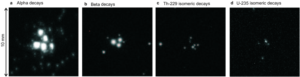
Signal comparison. CCD camera images of the phosphor screen reveal features that enable to distinguish type or origin of signals. Signals of different origin are shown in Extended Data Fig. 4. Each image corresponds to 4 s exposure time of the CCD chip (i.e. one frame). A wanted ion species was chosen by mass-to-charge selection with the QMS. Extended data Fig. 4 a shows decays on the MCP surface occurring within 5 min after extraction of 221Fr2+ ( s). Very large and intense signals are seen, with an average diameter of about 1 mm. Extended Data Fig. 4 b shows decays occurring within 45 min after extraction of 209Pb2+ ( h). The signals are significantly smaller and less intense than the ones caused by decays. The typical signal diameter is about 0.6 mm. Extended Data Fig. 4 c shows signals caused by the isomeric decay of 229Th starting to occur instantaneously with the accumulation of 229Th3+ on the MCP surface. The signals appear small and of low intensity with a typical signal diameter of about 0.3 mm. They are slightly smaller compared to the signals caused by decays, and clearly distinguishable from the events. Finally, signals caused by the isomeric 76 eV IC decay of 235(m)U ( min) are shown in Extended Data Fig. 4 d, taken within 30 min of extraction of 235U2+. They are comparable with the isomeric-decay signals of 229Th.
Half-life measurements. Two different half-life measurements are implemented. The first measurement leads to an upper limit for the isomeric half-life in neutral thorium. To obtain this limiting value, a pulsed 229(m)Th2+ ion beam is produced by applying a gate voltage of 0.5 V to the last RFQ electrode. The gate is opened for 500 ms and is then closed for 1700 ms, while ions are accumulated in the RFQ continuously (a maximum storage time of about 1 minute is obtained for Th2+). Strong ion pulses are produced when the QMS is set to extract 229Th2+. This is controlled by applying an MCP surface voltage of about V, yielding strong ion-impact signals. The CCD camera acquires images of 1 s exposure time only when the beam gate is closed. To ensure that the gate is actually closed, the camera is started 500 ms after applying the gate voltage. The camera is stopped after 1,200 ms in parallel to the gate opening, in order to acquire one image per pulse. It is reconfirmed that the camera does not acquire pictures at times of ion impact. By the sequence 1,200 frames (corresponding to 1,200 s total exposure time) are evaluated. No signal is obtained, which means that the isomer half-life must be below 1 second, allowing for charge exchange of the 229Th2+ ions on the MCP surface.
In a second measurement, a lower limit of the isomeric lifetime in 229Th2+ is found. For this purpose, 229(m)Th2+ ions are stored in the RFQ, by applying a gating voltage of 5 V to the last RFQ electrode. After storage, the ion cloud is accelerated onto the MCP surface to examine survival of the isomeric state by detected internal conversion. The half-lives, that can be probed by this method are limited by the storage times of Th2+ in the RFQ. A one minute storage time is easily accessible without significant ion loss. For this measurement the ions are accumulated for 10 s in the RFQ, where they are stored. After 10 seconds the 233U source offset is reduced to 0 V, preventing additional recoil ions from leaving the buffer-gas stopping cell. Then the ions are stored for one minute in the RFQ, waiting for the isomeric decay to occur. Afterwards, the gate voltage is also reduced to 0 V and the isomeric decay is read from the MCP detector. To reduce the dark count, the CCD camera is triggered to only acquire images when the ions are released. In this way, 200 pulses are evaluated with 3 imaged frames per pulse (4 s exposure time for each frame). A clear signal is seen when the QMS is set to extract 229Th2+, from which is inferred a half-life greater one minute. To eliminate signal contribution from a long-lived emitter, which might have populated the 229Th2+ mass peak by molecular formation (e.g. oxides), a measurement of the background rate is performed afterwards for 1 hour and no signal is obtained.
Exclusion of nuclear background based on signal comparison between 229Th2+ and 229Th3+ (Extended Data Table. 1 no. 4). All potential background contributions together with the relevant means of exclusion are listed in Extended Data Table. 1. The given measurement numbers refer to this figure.
It was discussed that the parallel occurrence of the signal in the and charge states (Fig. 4 b, first row) is already sufficient to exclude nuclear background as potentially originating from short-lived daughter nuclides. The reason is that only thorium can be expected to be extracted to a significant amount in the charge state, due to its low 3rd ionisation potential of only 18.3 eV (see Extended Data Table 2), which is below the first ionisation potential of He (24.6 eV). Thus, during stopping in the helium environment, it is energetically favourable for the electrons to stay attached to the helium atoms instead of reducing the thorium charge state. Experimentally, a reduced extraction for all short-lived daughter nuclides (of atomic number or below) by three to four orders of magnitude is found in the compared to the charge state [45]. In case of signals not caused by 229Th, the same reduction of signal intensity would be expected when comparing the and charge states. This, however, is not observed. For completeness, all ionisation potentials [10] for the elements which are potentially contained in the source material are listed in Extended Data Table 2. Also the heavier elements possess low ionisation potentials, however, they cannot explain the observed signal, because their half-lives are significantly longer. Further, mass-peak shifts from heavier to lighter masses cannot be explained by the population of molecular side-bands.
Exclusion of nuclear background based on signal comparison between 229Th originating from chemically purified and unpurified 233U sources (Extended Data Table 1 no. 5).
Isomeric-decay measurements were also performed with the new chemically purified 233U source of 90 mm diameter (source 3, 290 kBq). The thorium ions were collected in the and charge states for 2,000 s, while detection was performed in parallel. Compared to source 1, these measurements resulted in times higher isomeric count rate ( cts/s). This enhancement occurs due to the reduced source thickness, leading to a higher -recoil efficiency. The results of these measurements are shown in Fig. 4 b, third row.
If signals were caused by a decay of any of the short-lived daughter nuclides, a significant decrease in signal intensity compared to source 1 should occur, due to the chemical purification factor of more than 250. The fact that this is not the case further serves to exclude radioactive decay of short-lived isotopes as a signal contribution.
Exclusion of nuclear background based on signal appearance and the 229mTh half-life limit (Extended Data Table 1 no. 6). It was shown that the uniquely strong signal shape excludes any decay as contributor to the observed decay events (see Extended Data Fig. 4). This information, in combination with the observed short decay half-life (in the sub-second region), is already sufficient to exclude any nuclear origin of the signal except for the isomeric decay of 229Th.
While the uranium-source material predominantly consists of 233U, in source 1, trace amounts of other nuclides are also included (232U, 238Pu, 239Pu, 231Pa) together with their decay daughters [45]. Even further nuclides could potentially be present, although they have not been experimentally observed. A complete list of nuclides potentially contained in the source material (produced by neutron irradiation in a nuclear reactor) is shown in Extended Data Fig. 5. Also their half-lives and decay branching ratios are listed [1]. For completeness, all populated nuclides are shown, even if their activity can be assumed to play only a negligible role due to their small branching ratio or due to a long half-life of the mother nuclide. A complete list of potentially contributing isomers is given in Extended Data Table 3, together with their corresponding excitation energies and half-lives [1]. Note that excited states with half-lives in the s range or shorter do not have to be considered, because the extraction time from the source is in the ms range [9].
As can be inferred, there is no pure emitter or isomer contained, which could potentially explain the detected signal, except for the 0.8 s isomeric state in 207Pb. This isomeric state, however, is populated only by a fraction of from the decay of 211Po, which itself is not part of the main decay chains.
Furthermore, the 229Th isomeric transition is the only known nuclear transition which is expected to reveal the observed strong dependence of its half-life on the electronic environment. Thus the detected signal cannot be explained by any nuclear decay other than the decay of the 229Th first excited nuclear state.
Exclusion of nuclear background by search for and decays using Si and LN2 cooled Si(Li) detectors (Extended Data Table 1 no. 7). To further substantiate the evidence, the extracted ions (when operating the QMS for collection of 229Th2+ or 229Th3+) are directly accumulated on the surface of two different silicon detectors. The first detector is optimised for -particle detection in order to provide a further exclusion of decays as a cause of the detected signals. The second detector is used in order to exclude decays or high-energy internal conversion electrons.
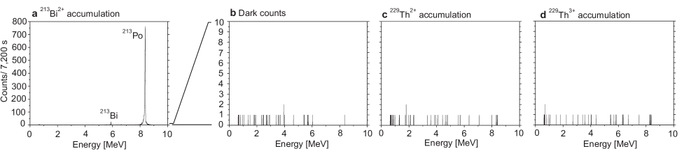
For the exclusion of decays an ion-implanted silicon charged particle detector (Ametek, BU-014-150-100) is used. This detector is mounted directly behind the extraction triode with about 5 mm distance, replacing the CsI-coated MCP detector. A charge sensitive preamplifier (CSTA) and a shaping amplifier (Ortec, model 571) are used for signal processing. The spectra are acquired by a multi-channel analyzer (Amptek, MCA-8000A). The detector is operated at a 20 V bias voltage and a V offset is applied to the whole system in order to collect the ions directly on the detector surface. To allow also for mass scans as required for the calibration of the QMS an MCP detector (Hamamatsu, type F2223) is mounted sideways at 90° to the extraction triode. During QMS calibration, a surface voltage of V is applied to the MCP, which is sufficiently high to attract the ions in spite of its off-axis position. After the QMS has been set to extract the desired ion species, the MCP surface voltage is reduced to V, so ions are collected on the Si-detector surface. In this way, four different measurements were performed each with 2 hours acquisition time: one during the extraction of 213Bi2+ (2.0 cts/s) in order to prove the functionality of the detector system, one dark count measurement ( cts/s), one during the extraction of 229Th2+ ( cts/s) and one during the extraction of 229Th3+ ( cts/s). The corresponding spectra are shown in Extended Data Fig. 6 a-d. As expected, no entries above background are visible in the energy range where -particles from 229Th would appear (4.7-5.1 MeV) during the extraction of 229Th in the or charge state, as the half-life of the 229Th decay is 7932 years and thus practically no decays occur within the duration of these comparatively short measurements. The fact that no line from any -decaying nucleus is visible in the spectra allows excluding -decays as the origin of the 0.25 cts/s-signal measured on the MCP in the search for the isomeric decay of 229mTh: had this signal originated from -decays, a total of about 1,800 cts should be seen in a 2 hour measurement with the Si detector, which would have been easily visible.
While decays as a signal contribution have already been excluded by half-life arguments, a further way to exclude them is given by direct detection. For this purpose a liquid nitrogen cryogenically cooled Si(Li) detector (Canberra, type ESLB-3000-300) is used, replacing the above mentioned Si detector. It is operated in combination with a preamplifier with a cooled FET stage (Eurisys Measures, PSC 761) and a shaping amplifier (Ortec, model 572). Again spectra are acquired by a multi-channel analyzer (Amptek, MCA-8000A). A bias voltage of V is applied to the front surface, such that no further offset is required. The detector is mounted at 5 mm distance to the triodic extraction system. Four different measurements were performed, each with 10 hours acquisition time: one dark-count measurement (0.47 cts/s), one during the extraction of 229Th2+ (0.44 cts/s), one during the extraction of 229Th3+ (0.48 cts/s) and one during the extraction of 209Pb2+ (2.13 cts/s), the latter to prove the functionality of the detection system. If the detected signals were decays or high-energy internal-conversion electrons, the expected enhancement of the integrated signal rate of (0.250.1) cts/s (for source 1) would have been detected easily.
Prospects for energy determination. A precise determination of the isomer’s energy is one of the most important prerequisites for the development of a nuclear frequency standard. The direct detection of the isomeric decay opens new perspectives for such an energy determination. In the presented work, the IC decay channel in the neutral thorium atom is investigated. Any energy determination based on this direct detection will require energy spectroscopy of the IC electrons emitted in the isomeric decay.
Several techniques for electron-energy spectroscopy of different precisions and complexities are known. The highest known precision is provided by hemispherical electron energy analysers, which possess resolutions in the range of a few meV [49]. While being also among the most complex devices for spectroscopy, there is a tradeoff between energy resolution and signal contrast. This problem can be solved by ion-beam pulsing. When applying an RFQ buncher, ion bunches of a few 10 ns pulse length can be produced [11]. These bunches are significantly shorter than the expected isomeric lifetime in the neutral thorium atom, which is predicted to be in the s range. Such ion beam pulsing would not only allow to determine the isomer’s half-life in the neutral thorium atom, but also to suppress any background by several orders of magnitude (depending on the exact isomeric half-life) if the electron detector is triggered in accordance with these pulses. This improvement in signal-to-background ratio will make high resolution electron spectroscopy applicable to the problem of energy determination of the isomeric state.
A significantly simpler sort of electron spectrometer is provided by retarding field analysers, which consist of a set of concentric hemispherical grids [12]. While this technique is significantly easier to apply, the achieved energy resolution is typically in the range of a few 100 meV. The expected low signal-to-background ratio of this technique will again make short ion-beam pulsing an important tool.
Independent of the applied technique for electron spectroscopy, charge exchange is required for the thorium ions in order to trigger the IC decay. In the simplest approach, this charge exchange is achieved by deposition of the thorium ions on a surface. This technique, however, is expected to influence the energy of the IC electrons as the work function of the surface material has to be considered [13]. In case of CsI, as being the coating material of the MCP used for all presented detections, the work function is 6.2 eV and thus close to the first ionisation potential of thorium [14]. For this reason no significant influence on the reported energy of the IC electrons is expected. For a precise energy determination, however, a careful investigation of surface influences is required. This must include the collection of the thorium ions on different surface materials with different work functions.
An alternative to the collection on a surface could be provided by collision with an atom beam. By crossing the thorium ion beam with a beam of, for example, caesium atoms, charge exchange will trigger the isomeric decay and could lead to an improved energy determination as no surface influences have to be considered [15].
References
- [1] Maier, H.J., Grossmann, R. & Friebel, H.U. Radioactive targets for nuclear accelerator experiments. Nucl. Instrum. Meth. B 56/57, 926-932 (1991).
- [2] Grossmann, R., Maier, H.J. & Friebel, H.U. The new hot-lab facility for radioactive target preparation at the University of Munich. Nucl. Instrum. Meth. A 397, 39-45 (1997).
- [3] Vascon, A. et al. Elucidation of constant current density molecular plating, Nucl. Instrum. Meth. A 696, 180-191 (2012).
- [4] Haettner E. A novel radio frequency quadrupole system for SHIPTRAP & new mass measurements of rp nuclides, Ph.D. thesis, Univ. Giessen, Germany (2011).
- [5] Brubaker, W.M. An improved quadrupole mass analyser. Advances in mass spectrometry 4, 293 (1968).
- [6] Wiza, J.L. Microchannel plate detectors. Nucl. Instrum. Methods 162, 587-601 (1979).
- [7] Rispoli, R. et al. ELENA MCP detector: absolute efficiency measurement for low energy neutral atoms. Proc. SPIE 8450, Modern Technologies in Space- and Ground-based Telescopes and Instrumentation II, 84505L (2012), doi: 10.1117/12.926185.
- [8] Bay, H.L., Winters, H.F., Coufal, H.J. & Eckstein, W. Energy transfer to a copper surface by low energy noble gas ion bombardment. Appl. Phys. A 55, 174-278 (1992).
- [9] Neumayr, J.B. The buffer-gas cell and the extraction RFQ for SHIPTRAP. Ph.D. thesis, Univ. Munich, Germany (2004).
- [10] Kramida, A., Ralchenko, Yu. & Reader, J. NIST Atomic Spectra Database (ver. 5.2), [Online]. Available at http://physics.nist.gov/asd [2015, June 16]. National Institute of Standards and Technology, Gaithersburg, MD.
- [11] Plaß, W.R. et al. Isobar separation by time-of-flight mass spectrometry for low-energy radioactive ion beam facilities. Nucl. Instrum. Meth. B 266, 4560-4564 (2008).
- [12] Palmberg, P.W. Optimization of auger electron spectroscopy in LEED systems. Appl. Phys. Lett. 13 5, 183-185 (1968).
- [13] Hotop, H. Detection of metastable atoms and molecules. Experimental Methods in the Physical Sciences 29 B, 191-215 (1996).
- [14] Poole, R.T., Jenkin, J.G., Liesegang, J. & Leckey, R.C.G. Electronic band structure of the alkali halides. I. Experimental parameters. Phys. Rev. B 11-12, 5179-5189 (1975).
- [15] Yamakita, Y. et al. A highly sensitive electron spectrometer for crossed-beam collisional ionization: A retarding-type magnetic bottle analyzer and its application to collision-energy resolved Penning ionization electron spectroscopy. Rev. Sci. Instrum. 71-8, 3042-3049 (2000).
| No. | Way of background exclusion | Type of background | |||
|---|---|---|---|---|---|
| A | B | C | D | ||
| 1 | Signal comparison between 229Th2+ and 233U2+ | x | x | ||
| 2 | Comparative 229Th2+ and 233U2+ signal behaviour as a function of MCP surface voltage | x | x | ||
| 3 | Signal comparison between 229Th and 230Th | x | x | x | |
| 4 | Signal comparison between 229Th2+ and 229Th3+ | x | |||
| 5 | Signal comparison between 229Th originating from chemically purified and unpurified 233U sources | x | |||
| 6 | Exclusion based on signal appearance and the 229mTh half-life limit | x | |||
| 7 | Search for and decays using Si and LN2 cooled Si(Li) detectors | x | |||
| Element | Atomic no. | 1+ [eV] | 2+ [eV] | 3+ [eV] |
|---|---|---|---|---|
| Curium | 96 | |||
| Americium | 95 | |||
| Plutonium | 94 | |||
| Neptunium | 93 | |||
| Uranium | 92 | |||
| Protactinium | 91 | |||
| Thorium | 90 | |||
| Actinium | 89 | |||
| Radium | 88 | |||
| Francium | 87 | |||
| Radon | 86 | |||
| Astatine | 85 | |||
| Polonium | 84 | |||
| Bismuth | 83 | |||
| Lead | 82 | |||
| Thallium | 81 | |||
| Mercury | 80 |
| Isomer | Excitation energy | Half-life | Decay channel | Population |
|---|---|---|---|---|
| 244mCm | 1.04 MeV | 34 ms | IT: 100.00 % | not populated |
| 242m1Am | 48.6 keV | 141 a | IT: 99.55 %, : 0.45 % | 100 % populated |
| 242m2Am | 2.20 MeV | 14.0 ms | SF: 100 %, %, IT | not populated |
| 235mU | 76 eV | 26 min | IT: 100 % | 70 % from 239Pu |
| 234mPa | 73.9 keV | 1.16 min | : 99.84 %, IT: 0.16 % | 78 % from 234Th |
| 229mTh | 7.8 eV | unknown | unknown | 2 % from 233U |
| 212mPo | 2.922 MeV | 45.1 s | : 99.93 %, IT: 0.07 % | not populated |
| 211mPo | 1.462 MeV | 25.2 s | : 99.98 %, IT: 0.02 % | not populated |
| 215mBi | 1.348 MeV | 36.9 s | IT: 76.2 %, : 23.8 % | not populated |
| 212m1Bi | 0.250 MeV | 25.0 min | : 67.0 %, : 33.0 % | not populated |
| 212m2Bi | 1.91 MeV | 7.0 min | : 100 % | not populated |
| 210mBi | 0.271 MeV | a | : 100 % | not populated |
| 207mPb | 1.633 MeV | 0.806 s | IT: 100 % | % from 211Po |
| 207mTl | 1.348 MeV | 1.33 s | IT: 100 % | % from 211Bi |
| 206mTl | 2.643 MeV | 3.74 min | IT: 100 % | not populated |