J-PET: a new technology for the whole-body PET imaging††thanks: Presented at the 2nd Jagiellonian Symposium on Fundamental and Applied Subatomic Physics, Kraków, Poland, June 4–9, 2017.
Abstract
The Jagiellonian Positron Emission Tomograph (J-PET) is the first PET built from plastic scintillators. J-PET prototype consists of 192 detection modules arranged axially in three layers forming a cylindrical diagnostic chamber with the inner diameter of 85 cm and the axial field-of-view of 50 cm. An axial arrangement of long strips of plastic scintillators, their small light attenuation, superior timing properties, and relative ease of the increase of the axial field-of-view opens promising perspectives for the cost effective construction of the whole-body PET scanner, as well as construction of MR and CT compatible PET inserts. Present status of the development of the J-PET tomograph will be presented and discussed.
29.40.Mc, 87.57.uk, 87.10.Rt, 34.50.-s
1 Introduction
Positron emission tomography is a medical technique used mainly for cancer studies as well as control of radio- and chemo-therapies. Before examination, the patient is being injected with a radioactive marker, which emits positrons. After traveling for short distance, positron-electron annihilation occurs and in most cases a pair of almost back-to-back quanta are produced.
Reconstruction of the annihilation position, by using informations from annihilation quanta, is providing a spatial density distribution of injected marker inside patients body. By selecting different tracers, one can select different metabolical processes to observe during a scan.
All available state of the art scanners are detecting quanta by crystal scintillators [1, 2, 3]. Their main advantage is large stopping power, high probability of photoelectric effect and good energy resolution.
One of the challanges in the PET tomography is the simultaneous imaging of the whole human body.
Due to the high cost of crystal scintillators, a production of the commonly available whole body scanner based on crystals seems implausible. Currently only about 20 cm along the body can be simultanousely examined at single bed position [1]. In case of whole-body scan, several overlapping bed positions are needed.
Currently only 1% of quanta emitted from patien’s body are collected [4]. Extension of the scanned
part from around 20 cm to 200 cm would improve the sensitivity and signal-to-noise ratio. The radiation dose needed for whole body scan can be also reduced and usage of shorter living tracers will be simplified.
To address this problem several different designs of whole body scanners were introduced based on resistive plate
chamber (RPCs) [5], straw tubes [7, 6] and crystal scintillators [4].
The J-PET group proposes the usage of plastic scintillators as detection material for positron emission tomography [8]. This will allow a
construction of cost effective whole-body scanner, due to less expensive detector material [8, 9]. In
addition the readout can be placed outside of detection chamber simplifying PET/MR hybrid construction and enabling extension of the axial field of view (AFOV) without significant increase of costs. The costs of the electronic readout is not changing for the extended J-PET, because the number of photomultipliers and electronic channels remains independent of the AFOV.
In order to compare a performance of the crystal based PET tomographs and the J-PET built from strips of plastic scintillators we introduced a figure of merit (FOM) for the whole body imaging [10] by analogy to the figure of merits proposed earlier in [11, 12].
The whole body FOM is defined as a
probability of detection of annihilation event divided by the Coincidence Resolving Time (CRT) and the number of bed positions.
Comparions of such introduced FOM for the J-PET and scanner based on LSO crystals, with AFOV = 20 cm and CRT = 400 ps shows that one can overcome lower probability of detection of plastic
scintillators by using longer modules and more detection layers. For 50 cm long plastic modules, one expects already the
same performance for a whole-body scan as for commercial scanners, while the introduction of second layer should improve it a few times. It is
worth to note that the plastic scintillator modules could be even 2 m long, but this comes with a trade off the CRT,
which will decrease with elongation of modules [10].
In this paper the general concept of the J-PET scanner is described. Then, the previous prototype built out of 24
modules is presented along with the latest full scale prototype, based on 192 detection modules with 50 cm AFOV and
85 cm diameter of first layer and 115 cm diamater of last one. Initial TOF resolution studies are presented. Finally, conclusions and perspectives are given.
2 General concept of J-PET scanner
The J-PET tomgraph is constructed from axially arranged strips of plastic scintillators. Annihilation quanta with energy of 511 keV interact in plastic scintillators through Compton effect, in which deposited energy varies from event to event.
Due to the low light attenuation, plastic scintillators act as effective lightguides for photons produced by interaction of radiation, hence examination chamber can be built out of long modules placed along patients body.
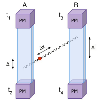
Each plastic strip is read out by photomultipliers at two ends (Fig. 1).
Since the readout will be placed outside of the diagnostic chamber, the main cost of extending the axial field of view of the scanner lays in cost of scintillating material.
The position of interaction of quanta with scintillator can be determined from time difference of light signal arriving at photomultipliers placed at each end of detection module:
| (1) |
where denotes the distance between the interaction point and the center of module, and stand for times of arrival of light signal at each side of scintillator and is an effective velocity of light signal within the scintillator. Then, the position of annihilation along Line Of Response (LOR) can be determined by usage of TOF method (see Fig. 1 for pictorial description):
| (2) |
where denotes distance of annihilation point from middle of LOR, and stands for the speed of light.
The J-PET predominantly uses time information instead of energy to acquire place of annihilation. Scintillating signals from plastics are very "fast" (typically 0.5 ns rise time and 1.8 ns decay time [13]). Such fast signals allow for superior time resolution and decrease pile-ups with respect to crystals detectors as e.g. LSO or BGO with decay times equal to 40 ns and 300 ns, respectively [14]. In order to take advantage of this superior timing properties of plastic scintillators and to decrease the dead time due to the electronic signal processing in J-PET, the charge measurement was replaced with measurement of TOT (Time Over Threshold). In order to improve the resolution of the scanner, signals are probed at four different constant thresholds at the rising and falling edge. The sampling of the signal depicted schematically in Fig. 2 is performed by the newly developed method based solely on FPGA units [15].
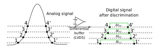
Sampling at few selected thresholds gives opportunity to improve the resolution of determination of time and place of interaction of quanta with detector by applying more advanced methods of reconstruction published in [16, 17, 18, 19, 20]. Data acquisition is performed in trigger-less mode and can handle stream of data up to 8 Gbps [21]. Utilisation of digital time measurement decreases price of the electronics as well as power consumption.
3 The 24th-modules prototype
The first working prototype of J-PET scanner, shown in Fig. 3, was constructed from 5x19x300 mm3 strips of BC-420 scintillators formed in a ring with 360 mm diameter. Each scintillator was read out by R4998 Hamamatsu photomultipliers and signals were probed at four levels by front end boards [15].
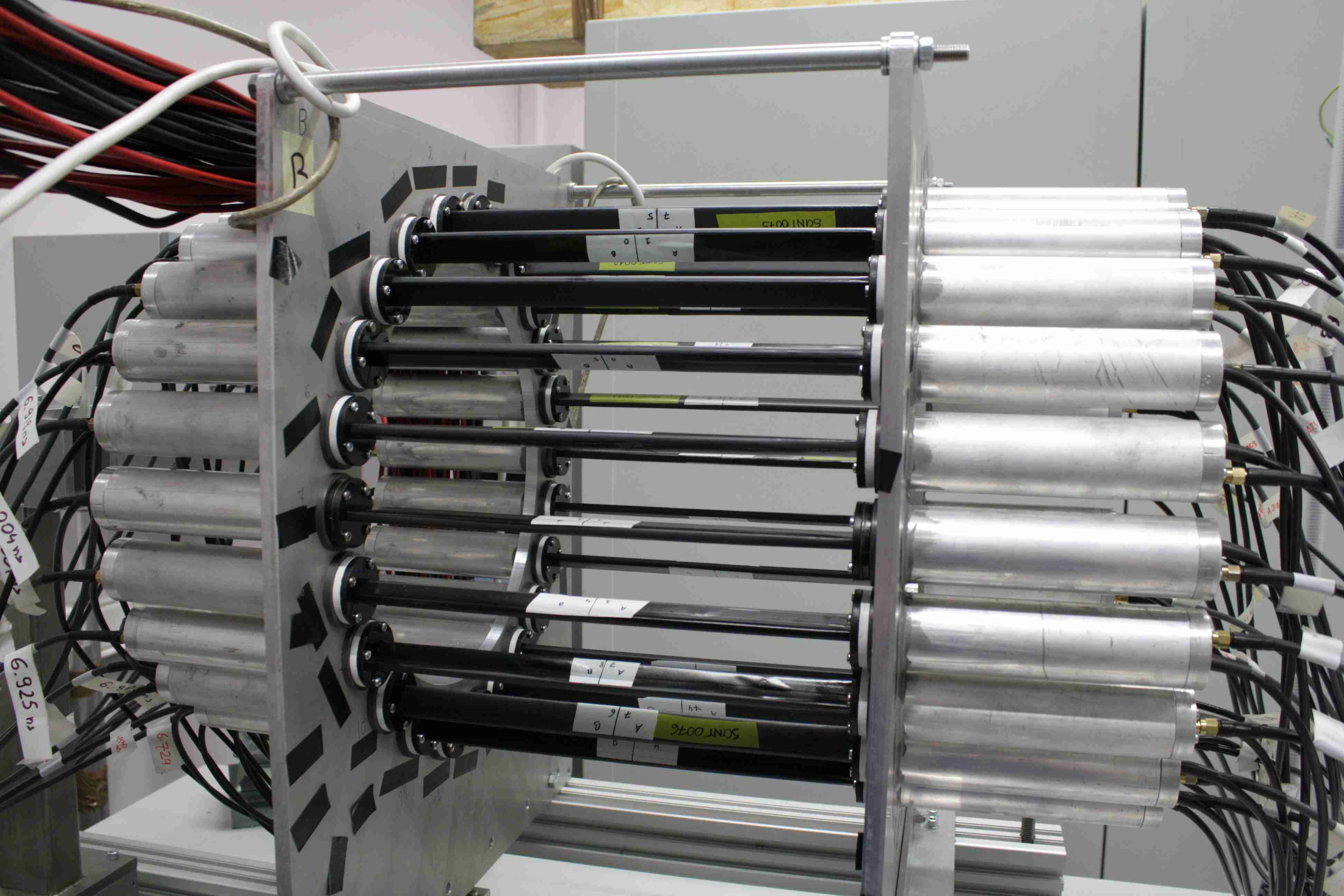
The main reason to build this prototype was to test electronic readout, develop calibration procedures and proceed from two modules studies to system where one has to control more detectors. The resulting CRT for this prototype was equal to 490 ps [22] which is comparable to the best currently available scanners [1, 2, 3]. Unfortunately, the amount of detection modules was not enough for the effective image reconstruction inside the chamber due to too many holes in acceptance. Nonetheless we have gained the necessary experience to know how to design and construct the full scale prototype.
4 First full scale J-PET prototype
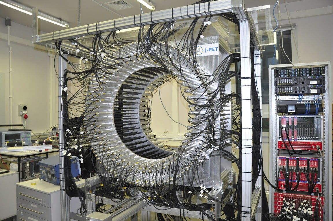
A full scale version of the prototype has been assembled from 192 detection modules, with each module constructed from 7x19x500 mm3 EJ-230 scintillators with two R9800 Hamamatsu photomultipliers coupled to each end. Modules were arranged in three, not overlaying rings (see Fig. 4). As with previous prototype, this setup was read-out by multi-constant-threshold boards [15] combined with TRB3 boards [23]. At present the prototype is in a commissioning and calibration phase.
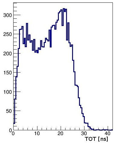
In a first approximation, as a measure of the energy deposition a sum of Time Over Threshold (TOT) values was used:
| (3) |
where, denote left and right photomultipier and subscript denotes the number of the selected threshold. An exemple sum of TOT spectrum is presented in Fig. 5.
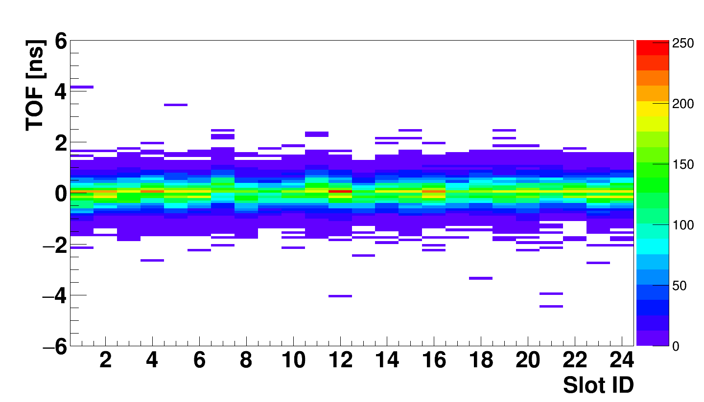
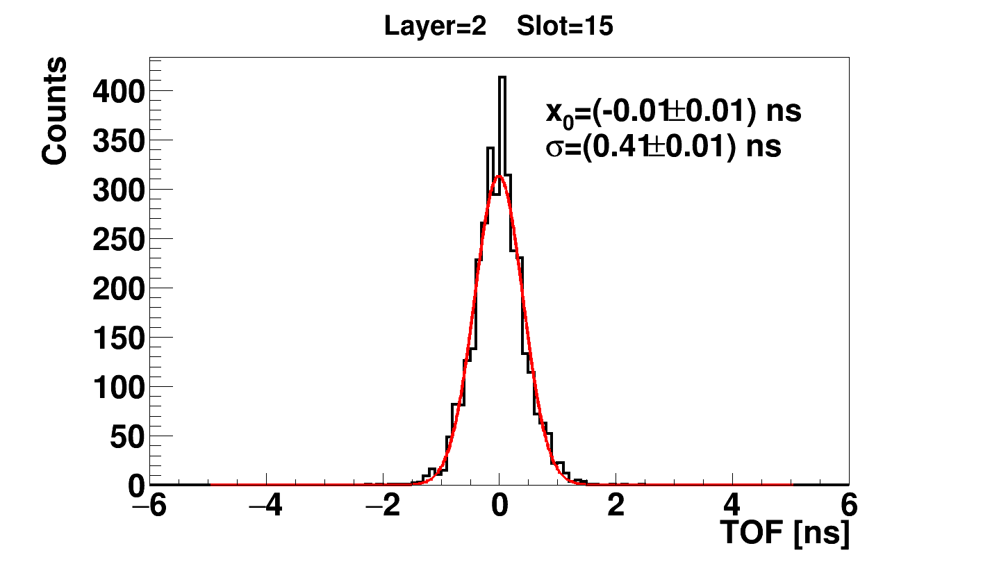
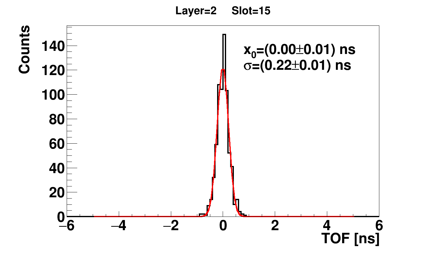
Since maximum energy deposited by annihilation quanta in plastic scintillators is equal to about 340 keV, an energy threshold of 200 keV will reduce the scattering of gamma quanta in the body of a patient to about the same level [24] as in previous commercial tomographs with low energy threshold of 300 or 350 keV [25]. Fig. 6 shows an exemplary spectrum of time of flight distributions as a function of the scintillator identifier (ID) after the first iteration of time synchronisation. In Fig. 7 an exemplary TOF distributions are presented before and after cut on Time Over Threshold corresponding to 200 keV. The results presented in aforementioned Figs. were obtained using J-PET Analysis Framework [26].
5 Conclusions and perspectives
In this article, first preliminary results from the commissioning of the first tomograph built from plastic scintillators were presented. Whole body J-PET prototype consists of 192 detection modules arranged axially in three layers forming a cylindrical diagnostic chamber with the inner diameter of 85 cm and the axial field-of-view of 50 cm. In order to take advantage of fast scintillating signals a Time Over Threshold is used to determine energy deposition inside detection modules. Due to selection of the material, such scanner will constitute cost-effective solution to whole body scans. The placement of detection modules along the patient’s body and readout at their end will reduce the price for the extention of the detection chamber, since main expeditures will be spent on plastic scintillators. Such design will also simplify the construction of PET/MR hybrids due to the placement of photomultipliers beyond magnetic fields. Preliminary studies of Coincidence Resolving Time show that it is possible to achieve the resolution of 220 ps (). One should note, that this result is obtained by using only a single threshold in time measurement and it can be improved by the utilisation of more complex methods. Three approaches were already checked: compressive sensing theory [17, 29], comparison of acquisited signal with averaged signals [19] and with library of model signals [30]. Initial Point Spread Function studies reported in ref. [31] show that values equal to 5-7 mm and 9-20 mm for transverse and longitudinal directions can be obtained. In order to improve the resolution along scanner length a method utilising Wavelength Shifting strips placed perpendicular to the detection modules was tested [32], indicating that even 5 mm () resolution can be achieved, with not optimized setup, leaving room for further improvement by optimisation of the WLS parameters and plastic strips. As next steps we intend to improve data selection and estimation of time of the interaction with the scintillator.
Acknowledgements
The authors acknowledge the technical support by A. Heczko, W. Migdał
and the financial support from the Polish National Center for Research and Development through grants INNOTECH-K1/IN1/64/159174/NCBR/12, and the LIDER-274/L-6/14/NCBR/2015, the EU and MSHE Grant no. POIG.02.03.00-161 00-013/09, National Science Center Poland through grant No. 2016/21/B/ST2/01222 and by the Ministry for Science and Higher Education through grants No. 7150/E-338/M/2017 and 7150/E-338/SPUB/2017/1. B. C. Hiesmayr acknowledges
gratefully the Austrian Science Fund FWF-P26783.
References
- [1] J.S. Karp et al., J. Nucl. Med. 49, 462 (2008) doi:10.2967/jnumed.107.044834.
- [2] P.J. Slomka et al., Semin. Nucl. Med. 46, 5 (2016) doi:10.1053/j.semnuclmed.2015.09.006 https://doi.org/.
- [3] S. Vandenberghe et al., EJNMMI Phys. 3, 3 (2016) doi:10.1186/s40658-016-0138-3.
- [4] S. R. Cherry et al., Sci. Trans. Med. 9, eaaf6169 (2017) doi:10.1126/scitranslmed.aaf6169.
- [5] A. Blanco et al., IEEE Trans. Nucl. Sci. 53, 2489 (2006) doi:10.1109/TNS.2006.876005.
- [6] N. N. Shehad et al., IEEE 2005 Nucl. Sci. Symp. Conf. Rec. 5, 2895 (2005).
- [7] L. Sun et al., IEEE 2007 Nucl. Sci. Symp. Conf. Rec. 5, 3337 (2007).
- [8] P. Moskal et al., Bio-Alg. and Med-Sys. 7, 73 (2011) [arXiv:1305.5187 [physics.med-ph]].
- [9] P. Moskal et al., Nucl. Instrum. Methods Phys. Res. A 764, 317 (2014) [arXiv:1407.7395 [physics.ins-det]].
- [10] P. Moskal et al., Phys. Med. Biol. 61, 2025 (2016) [arXiv:1602.02058 [physics.ins-det]].
- [11] M. Conti et al., Phys. Med. 25, 1 (2009) https://doi.org/10.1016/j.ejmp.2008.10.001.
- [12] L. Eriksson et al., Phys. Med. Biol. 60, 1613 (2015).
- [13] A. Wieczorek et al., submitted to PLOS ONE.
- [14] G. B. Saha, Physics and Radiobiology of Nuclear Medicine, Fourth edition, 92 (2012).
- [15] M. Palka et al., JINST 12, P08001 (2017) [arXiv:1707.03565 [physics.ins-det]].
- [16] L. Raczyński et al., Phys. Med. Biol. 62, 5076 (2017) [arXiv:1706.00924 [physics.ins-det]].
- [17] L. Raczyński et al., Nucl. Instrum. Methods Phys. Res. A 786, 105 (2015) [arXiv:1503.05188 [physics.ins-det]].
- [18] L. Raczyński et al., Nucl. Instrum. Methods Phys. Res. A 764, 186 (2014) [arXiv:1407.8293 [physics.ins-det]].
- [19] P. Moskal et al., Acta Phys. Pol. A 127, 1495 (2015) [arXiv:1502.07886 [physics.ins-det]].
- [20] N. G. Sharma et al., Nukleonika 60 (4), 729 (2015) [arXiv:1508.07463 [physics.ins-det]].
- [21] G. Korcyl et al., Acta Phys. Pol. B 47, 491 (2016) [arXiv:1602.05251 [physics.ins-det]].
- [22] T. Bednarski, PhD thesis, 5 (2016).
- [23] M. Traxler et al., JINST 6, C12004 (2011) doi:10.1088/1748-0221/6/12/C12004.
- [24] P. Kowalski et al., Acta Phys. Pol. B 47, 549 (2016) [arXiv:1602.05402 [physics.med-ph]].
- [25] J. L. Humm et al., Eur. J. Nucl. Med. Mol. Imaging 30, 1574 (2003) doi:10.1007/s00259-003-1266-2.
- [26] W. Krzemien et al., Acta Phys. Pol. A A127 1491 (2015) [arXiv:1503.00465 [physics.ins-det]].
- [27] E. Kubicz et al., Acta Phys. Pol. B 47, 537 (2016) [arXiv:1602.05243 [physics.ins-det]].
- [28] M. Skurzok et al., Acta. Phys. Pol. A submitted arXiv:1710.05598 [physics.ins-det].
- [29] L. Raczyński et al., Nukleonika 61 (1) 35 (2016) [arXiv:1507.03799 [physics.ins-det]].
- [30] P. Moskal et al., Nucl. Instr. and Meth. Phys. Res. A 775, 54 (2015) [arXiv:1412.6963 [physics.ins-det]].
- [31] R. Shopa et al., Acta Phys. Pol. B, in Print arXiv:1710.11058 [physics.ins-det].
- [32] J. Smyrski et al., Nucl. Instrum. Methods Phys. Res. A 851, 39 (2017) [arXiv:1612.08571 [physics.ins-det]].