Radiation dominated implosion with nano-plasmonics
Abstract
Inertial Confinement Fusion is a promising option to provide massive, clean, and affordable energy for mankind in the future. The present status of research and development is hindered by hydrodynamical instabilities occurring at the intense compression of the target fuel by energetic laser beams.
A recent patent combines advances in two fields: detonations in relativistic fluid dynamics and radiative energy deposition by plasmonic nano-shells.
The compression of the target pellet can be moderate and rapid volume ignition is achieved by a laser pulse, which is as short as the penetration time of the light across the pellet. The reflectivity of the target can be made negligible, and the absorptivity can be increased by one or two orders of magnitude by plasmonic nano-shells embedded in the target fuel. Thus, higher ignition temperature can be achieved with modest compression. The short light pulse can heat the target so that most of the interior will reach the ignition temperature simultaneously. This makes the development of any kind of instability impossible, which would prevent complete ignition of the target.
pacs:
28.52.Av, 52.27.Ny, 52.35.Tc, 52.38.DxI Introduction
Inertial Confinement Fusion (ICF) is an ongoing activity aiming for ignition of small pellets of thermonuclear, deuterium-tritium (DT) fuel by high-power lasers. The main direction of activity aims for strong compression of the fuel, where the resulting adiabatic heating would ignite the fuel. The pulse and the compression should be large and strong enough to keep the compressed fuel together for sufficient time for ignition, due to the inertia of the compressed pellet. In the present work we present a patented idea how to achieve simultaneous volume ignition in the majority of the target Patent .
In the pellet the fusion reaction, , takes place at a temperature of keV. The produced (or ) particles are then deposited in the hot DT plasma and heat it further. This is the plasma self-heating (or -heating). The compression wave penetrates into the plasma with the speed of sound or with the speed of a compression shock. There are several facilities with different configurations attempting to achieve nuclear fusion this way. A comprehensive summary of these is presented in ref. RBOAH16 .
The up to now most successful configuration uses indirect drive. A spherical pellet of DT fuel of initial outer radius of 1143 m is targeted by laser beams. At the National Ignition Facility (NIF) the pellet has a hole in the middle, to reach better compression, and it has a thin ”ablator” layer, which reflects the incoming light Lindl1998 ; Lindl2004 ; Haan2011 . In this experiment the target capsule is indirectly ignited by the thermal radiation coming from the gold Hohlraum. The Hohlraum is heated by the radiation of 192 laser beams RBOAH16 ; Nora2015 . The incoming and reflected light exercised a pressure and compressed the pellet at NIF, to about m just before ignition. At this moment the hole in the capsule is already filled in and the target density was compressed to about 300-700 g/cm3, NIF11 ; RHL16 . Then this target showed the development of Rayleigh-Taylor instabilities, which reduced the efficiency of ignition.
The initial compression pulse (”low foot”) had lower frequency or longer wavelength of 100-300 nm, which therefore had a higher reflectivity on the target, and led to compression. The reflectivity of light is high ( ) for lower frequency light and decreasing with increasing frequencies. It becomes negligible at keV. The compression pulse was followed by a shorter, higher frequency ignition pulse. The higher frequency pulse has negligible reflectivity and decreasing absorptivity, having cm-1 at eV and cm-1 at keV. If we take a higher frequency, shorter wavelength of 20 nm in the X-ray range then the absorptivity of the DT fuel is about cm-1.HuCoGo14 This means that the full pulse energy is absorbed in cm m. That is in a thin surface layer. The internal domain is heated up due to adiabatic compression, up to ignition, but the major part of the approximately 10 m thin compressed surface layer remains cold and only 1 m is heated up at the outside surface. See Fig. 8 of Ref. HuCoGo14 .
II Considerations for the target
In the following consideration we could take (a) a compressed smaller initial state of radius m, which is then not compressed further but heated up further with a short penetrating light pulse. Alternatively we could (b) consider a solid ball of the same amount of DT fuel, which is then made transparent and ignited by a laser pulse without significant compression, of radius m . In this second case due to the smaller density we will need a more energetic short pulse but also 8 times longer because of the larger size.
Reference LCJ16 used a similar size target, with an outer ablator layer and initial compression. However, they used a special cone-in-shell configuration of the target. Through doping the target with Cu, they were able to project the K-shell radiation of the target when it was radiated by an ultraviolet driver beam. From their images in Figure 2 d-f of LCJ16 , we see that ignition is achieved in an area of approximately 50 m radius from the center of the target. By using a high-contrast laser and a 40 m cone tip they were able to increase the fast electron coupling to the core from to 10-15% by an increase in the core-density and decrease in the source-to-core distance. If this laser-to-electron conversion efficiency would be further increased, the total laser energy coupled to the core would also increase above 15%, which may be good if we want to achieve fast-ignition inertial-confinement-fusion.
Here we consider another configuration, without ablator layer and without too much pre-compression, using the early examples in Refs. C87 ; CS14 . Then we have a more dilute target fuel with about 640 m radius, similar to case (b). With a deuterium-tritium ice as fuel, the target density is taken to 1.062 g/cm3. We could increase this initial density, but only moderately to avoid the occurrence RT instability. This more dilute target a priory has smaller absorptivity. If we want to absorb the whole energy of the incoming laser light on 1.3 mm length, we need an absorptivity of cm-1. This is about the absorptivity of DT fuel for soft X-ray radiation of 1 nm wavelength. Longer wavelength radiation would have a larger absorptivity, and would be absorbed in the outside layers of the pellet.
III Simplified model and its evaluation
Consider a spherical piece of matter (E), which is sufficiently transparent for radiation. The absorptivity of the target matter is considered to be constant, such that the total energy of the incoming light is observed fully when the light reaches the opposite edge of the spherical target. This matter undergoes an exothermic reaction if its temperature exceeds .
The target matter is surrounded by a set of spherically distributed laser beams, which emit the radiation necessary to heat up E. Here, for simplicity, we are neglecting the expansion of the outer shell inwards as well as the expansion of the core, so that the core radius is taken to be constant. We will measure the length in units of m, and the time in units of m/c.
We intend to calculate the temperature distribution, , within the
sphere, as a function of time, , and the radial distance from
the center of the sphere, i.e. radius . We have two steps of the
evaluation:
(i) In the 1st step we calculate how much energy can reach a given point
at from the outside surface of the sphere. Here we have to take into
account that the outside thermal radiation starts at time ,
so there is no radiation before. The eventual, ”Low foot” type
pre-compression is not included in this dynamical calculation.
Furthermore, we must consider, which parts of the
outside surface can reach a point inside the
sphere at time , and which are on the backward light-cone of the
point at and time .
The integral for the energy density
reaching the point from this part of the two
dimensional outside surface of the sphere in unit time
interval, , is .
(ii) Then we have to add up the accumulated radiation at position
, for the previously obtained energy and to obtain the
time dependence of the temperature distribution, , we
have to integrate from , for each spatial position.
We perform the surface integral of step (i) in terms of integration
for the proper time of the radiation with a delta function, selecting
the surface element, which can reach the given internal point at a time.
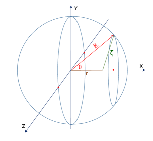
Let us study a point within the sphere, at a distance from the center. Choose the -axis passing through this point and the center of the sphere. See Fig. 1.
The surface area of a ring of the sphere at the selected polar angle is .
Step (i):
At a point at we receive radiation from a layer edge ribbon at
time . The radiation
at distance is decreasing as . The total radiation
reaching point from the ribbon at is
| (1) |
where c, and we should integrate this for the surface of all ribbons.
The average intensity of thermal radiation reaching the surface of the pellet amounts to per unit surface (m2) and unit time (m/c). Let us take a typical value for the energy of the total ignition pulse to be 2 MJ, in time 10 ps, then or .
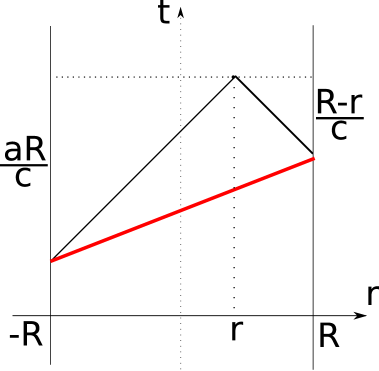
Up to a given time , the light can reach a space-time point (), inside the sphere from different points of the outside surface, which were emitted in different times. At early times it may be that none of the surface points are within the backward light-cone of the point (). At later times, from part of the surface points the light can reach (), while at times larger than c all internal points can be reached from any surface point of the sphere. Thus, we calculate first what energy density, , we get at a space-time point (), from earlier times. At a given point at measured from the center of the sphere (assuming that a constant fraction, , of the radiation energy is absorbed in unit length): 111 We are using the relation where -s are the roots of , i.e. . Now and so that the integrand is . The variable depends on (or ), so we should set the integral boundaries in terms of accordingly.
| (2) |
where the integral over gives . The time, , integral runs from the nearest point of the backward light cone to the surface of the sphere to the furthest point, . Here the parameter will be described later. See Fig. 2.
Now we introduce a new, dimensionless time variable: Thus,
| (3) | |||||
where c and is the upper boundary of the integral over the dimensionless time .
| (4) |
Here actually the integral over is adding up the contributions of those surface elements of the sphere, from where radiation reaches the internal point at at the same dimensionless time . In the first case the radiation does not reach the point at then, in the second part the radiation from the closest point of the sphere reaches but from the opposite point not yet, in the third case radiation reaches from all sides.
Thus the energy deposited in unit time at dimensionless time is
| (8) |
Step (ii):
Neglecting the compression and assuming constant specific heat ,
we get that , where is the
Boltzmann constant, and so
| (16) |
and so,
| (23) |
where the number density of uncompressed DT ice is
cm-3, and the leading constant, , is
| (25) |
If the absorptivity is varying, , then it follows:
| (26) |
The surface of the discontinuity is characterized by the contour line. If is the ignition temperature, then here the DT ignition takes place on this contour line in the space-time. The tangent of this line is if :
| (27) | |||
| (28) |
So the point where the space-like and time-like parts of the surface meet, from is :
| (29) |
This line separates the Space-like and Time-like branch of the discontinuity of .
The discontinuity initiates at and and it propagates first slowly inwards. Due to the radiative heat transfer the contour line of ignition, , accelerates inwards, and at it develops smoothly from space-like into a time-like discontinuity.
The same type of gradual development from space-like into time-like detonation occurs in the last, hadronization, phase of ultra-relativistic heavy ion collisions FO-HI . If we include radiative heat transfer in these scenarios, the transition from space-like to time-like deflagration will be gradual. This, however, requires more involved numerical calculations.
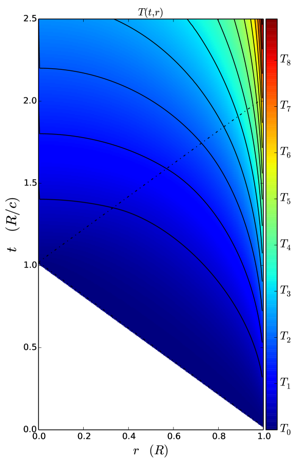
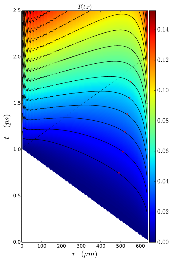
In Fig. 3 we see the constant temperature contour lines, const., in the space-time, from the analytical solution. For the first or second const. contour line the time-like detonation region extends from the center of the pellet to the half of radius R. This is only about 12% of the volume, so the time-like detonation, in itself, cannot achieve total simultaneous volume ignition, and in the outside region instabilities might develop!
IV Variable absorptivity
In order to study the effect of variable absorptivity we reformulated the numerical model to perform all integrals of the model numerically. This will enable us to study the configuration where the pellet is manufactured with nano-shells inside, which regulate the absorptivity of the DT ice pellet.
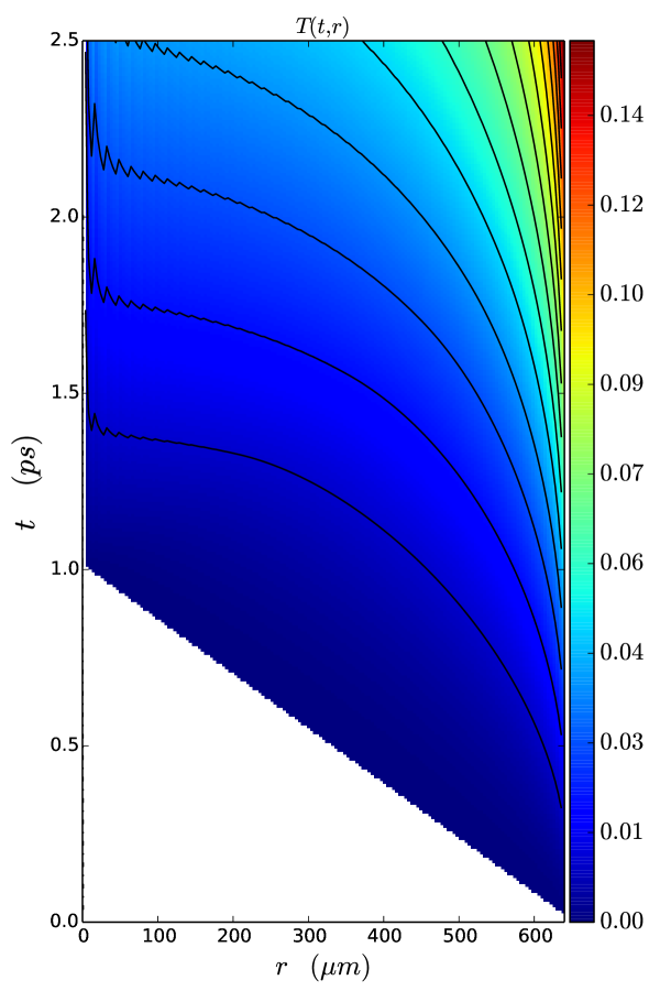
At first we still assumed constant absorptivity with the same value cm-1. In Fig. 4 the numerical solution gives qualitatively identical result, but at small radii the numerical uncertainty leads to visible fluctuations and somewhat smaller central temperature increase. The domain of time-like , i.e. simultaneous ignition takes place in the central part of the pellet up to a radius of m.
In Hu2014 , Rochester and NIF experimental data were studied and analysed with opacity data, extracted both from basic principles and from comparison with ICF experiments. The absorption coefficient (cm-1), defined by , and the Rosseland and Planck opacities, defined by , were estimated and used to simulate the space-time development of ICF direct ignition experiments.
In our previous calculations we used the absorption coefficient (cm-1), and the approximation that the intensity of the incoming laser light flux is sufficiently large, so that its decrease by the absorption is negligible.
With increased absorptivity one could reach more rapid heating. The fusion reaction rate per unit volume and unit time is , depends on the D and T densities, , and the reactivity, . Due to the fusion cross section, the reactivity is increasing up to about keV, and then decreases again. Thus, we could aim for a heating up to this temperature, with smaller pre-compression.
V Variation of absorptivity by Nanotechnology
Doping inertial confinement fusion pellets with golden nano-sphere shells enables us to achieve the desired variable absorptivity katsuaki2016 . Nano-shells irradiated by laser light exhibit a resonant light absorption, which can increase the plasmon field- strength by up to a factor of 40-100 or more N_Halas . At present experimentally realizable nano-shell sizes ranges for core sizes: 5-500 nm, and for shell thickness: 1-100 nm. In a fuel target prepared initially with implanted Au nano-shells, after pre-compression we can have nano-shells of a radius nm.
The resonant light frequency of the nano-shell can be tuned in a very wide range by changing the size and thickness of the nano-shell. If the Core versus the Shell thickness, is changed from 2 to 800 the resonant wavelength changed from to nm Loo04 . For our purposes of short wavelength, X-ray photons the smaller and relatively more thick nano-shells are relevant. An eventual pre-compression modifies the nano-shells in this direction.
At the resonant frequencies the nano-shells are able to absorb resonantly a rather high portion of incoming light. We can define the , and efficiencies, , , and , respectively Lee05 , where these coefficients, , describe how much part of the energy of the incoming light is absorbed or scattered by the nano-shell, compared to its geometrical cross-section, G, i.e. for a sphere of radius , .
The nano-shells can be tuned to either larger absorption efficiency or larger scattering efficiency. For our purposes the larger absorption efficiency is optimal. The resonance extinction or absorption efficiency can reach a factor 10 or even more Alam06 .
Thus, the absorptivity of the target material of the pellet can be regulated by the density of implanted nano-shells. The target DT fuel has a bulk absorption coefficient, (cm-1). If we implant nano-shells with cross section , with a density (cm-3) then the absorptivity will increase to
| (30) |
where the absorptivity of nano-shells, , is
| (31) |
For a nano-shell of nm the additional contribution would be cm2. Consequently for a typical nano-shell density James07 of cm3 and a , we can reach an additional absorptivity of
| (32) |
Higher nano-shell density and higher absorption efficiency can also be achieved. A pre-compression of the target fuel would further increase the absorptivity.
Absorption for DT densities in the range of g/cm3, K were obtained in the range of
as the light frequency increased to keV. I.e. the typical light mean free path was about 1-10m. Thus, while for low frequency radiation, eV the DT target is quite opaque, at higher frequencies or energy it is much more transparent. This leads to the result that the initial lower energy (”Low foot”, ”High foot”) pulse leads primarily to compression. This effect is enhanced further with the application of the thin ablator sheet on the surface of the pellet Benredjem2014 .
The additional opacity of nano-shells with typical nano-shell densities can increase the absorptivity by up to
which makes the fast ignition possibilities very versatile in this light frequency range. We can experiment with variable absorptivity, which is the normal high temperature, high frequency absorptivity of the DT fuel, cm-1 at the outer edge of the pellet (i.e. at m) while in the center, it is , (i.e. about up to 30 times more). The space time profile of the ignition, will then depend on the radial profile of the increasing nano-shell doping towards the center of the pellet. We could optimize this by achieving the largest simultaneous volume ignition domain, which eliminates the possibility of developing instabilities.
VI Conclusions and discussions
Using nano-technology for ICF is mentioned recently Nano-Rods . By placing aligned nano-rods or nano-wires on the surface of the pellet and irradiating irradiating it with femtosecond laser pulses of relativistic intensity, leads to a plasma with peak electron intensity and pressure. However, this pressure would lead to a pressure driven adiabatic compression and heating, which can lead to Rayleigh-Taylor Instabilities, preventing simultaneous volume ignition.
In this model estimate, we have neglected the compression of the target solid fuel ball, as well as the reflectivity of the target matter. The relatively small absorptivity made it possible that the radiation could penetrate the whole target. With the model parameters we used the characteristic temperature was , which is larger than the usually assumed ignition temperature, while our target is not compressed so the higher temperatures may be necessary to reach ignition according to the Lawson criterion. If we can achieve ignition at somewhat lower temperature than , the ignition surface in the space time includes a substantial time-like hyper-surface, where instabilities cannot develop, because neighboring points are not causally connected.
From looking at the constant temperature contour lines in function of distance and time (Fig. 5), we see that the detonation at a higher critical temperatures, occurs when the radiation reaches the matter from the other side also. At these contour lines of keV, about 90% of the interior ignites at the same time, so the ignition is simultaneous for about 73% of the total volume. In this domain no instabilities may occur and the thinner external crust is not the origin of instabilities according to the experience from LLNL.
We can also apply this model is to a pre-compressed, more dense target, which is transparent and has larger absorptivity. In this situation the ignition temperature can be somewhat smaller, but we still can optimize the pulse strength and pulse length to achieve the fastest complete ignition of the target.
We can see if we neglect the importance of the speed of light, the theory would be far-fetched from reality. It is important to use the proper relativistic treatment to optimize the fastest, more complete ignition, with the least possibility of instabilities, which reduce the efficiency of ignition.
Acknowledgements
Enlightening discussions with Igor Mishustin, and Horst Stöcker are gratefully acknowledged. This work is supported in part by the Institute of Advance Studies, Kőszeg, Hungary.
References
References
- (1) L. P. Csernai, N. Kroo and I. Papp, Procedure to improve the stability and efficiency of laser-fusion by nano-plasmonics method, Patent # P1700278/3 of the Hungarian Intellectual Property Office.
- (2) R. Betti and O.A. Hurricane, Inertial-confinement fusion with lasers. Nature Physics 12, 435 (2016).
- (3) J. D. Lindl, Inertial Confinement Fusion (Springer, 1998).
- (4) John D. Lindl, Peter Amendt, Richard L. Berger, S. Gail Glendinning, Siegfried H. Glenzer, Steven W. Haan, Robert L. Kauffman, Otto L. Landen1 and Laurence J. Suter, The physics basis for ignition using indirect-drive targets on the National Ignition Facility, Phys. Plasmas 11, 339 (2004).
- (5) S. W. Haan, J. D. Lindl, D. A. Callahan, D. S. Clark, J. D. Salmonson, B. A. Hammel, L. J. Atherton, R. C. Cook, M. J. Edwards, S. Glenzer, A. V. Hamza, S. P. Hatchett, M. C. Herrmann, D. E. Hinkel, D. D. Ho, H. Huang, O. S. Jones, J. Kline4, G. Kyrala, O. L. Landen, B. J. MacGowan, M. M. Marinak, D. D. Meyerhofer, J. L. Milovich, K. A. Moreno, E. I. Moses, D. H. Munro, A. Nikroo, R. E. Olson, K. Peterson, S. M. Pollaine, J. E. Ralph, H. F. Robey, B. K. Spears, P. T. Springer, L. J. Suter, C. A. Thomas, R. P. Town, R. Vesey, S. V. Weber, H. L. Wilkens, and D. C Wilson, Point design targets, specifications, and requirements for the 2010 ignition campaign on the National Ignition Facility Phys. Plasmas 18, 051001 (2011).
- (6) R. Nora, W. Theobald, R. Betti, F. J. Marshall, D.T. Michel, W. Seka, B. Yaakobi, M. Lafon, C. Stoeckl, J. Delettrez, A.A. Solodov, A. Casner, C. Reverdin, X. Ribeyre, A. Vallet, J. Peebles, F.N. Beg, and M.S. Wei, Gigabar Spherical Shock Generation on the OMEGA Laser, Phys. Rev. Lett. 114, 045001(2015).
- (7) D. S. Clark, M. M. Marinak, C. R. Weber, D. C. Eder, S. W. Haan, B. A. Hammel, D. E. Hinkel, O. S. Jones, J. L. Milovich, P. K. Patel, H. F. Robey, J. D. Salmonson, S. M. Sepke, and C. A. Thomas, Radiation hydrodynamics modeling of the highest compression inertial confinement fusion ignition experiment from the National Ignition Campaign, Phys. Plasmas 22, 022703 (2015).
- (8) V.H. Reis, R.J. Hanrahan, W.K. Levedahl, The big science of stockpile stewardship. Physics Today 69, 46 (2016).
- (9) S.X. Hu, L.A. Collins, V.N. Goncharov, T.R. Boehly, R. Epstein, R.L. McCrory, and S. Skupsky, First-priciples opacity table of warm dense deuterium for inertial-confinement-fusion applications. Phys. Rev. E 90, 033111 (2014).
- (10) L.C. Jarrott, M.S. Wei, C. McGuffey, A.A. Solodov, W. Theobald, B. Qiao, C. Stoeckl, R. Betti, H. Chen, J. Delettrez, T. Döppner, E.M. Giraldez, V.Y. Glebov, H. Habara, T. Iwawaki, M.H. Key, R.W. Luo, F.J. Marshall, H.S. McLean, C. Mileham, P.K. Patel, J.J. Santos, H. Sawada, R.B. Stephens, T. Yabuuchi, and F.N. Beg, Visualizing fast electron energy transport into laser-compressed high density fast-ignition targets. Nature Physics 12, 499 (2016).
- (11) L.P. Csernai, Detonation on a time-like front for relativistic systems, Zh. Eksp. Teor. Fiz. 92, 379-386 (1987).
- (12) L.P. Csernai and D.D. Strottman, Volume ignition via time-like detonation in pellet fusion Laser and Particle Beams 33, 279-282 (2015).
- (13) L.P. Csernai: Introduction to Relativistic Heavy Ion Collisions, (John Wiley & Sons, Cichester, England, 1994); U.W. Heinz and P.F. Kolb, Phys. Lett. B 542, 216 (2002); R. Chatterjee, et al., Phys. Rev. Lett. 96, 202302 (2006); E. Molnar, et al., J. Phys. G 34, 1901 (2007); E. Frodemann, et al., J.Phys. G 34, 2249 (2007); L.P. Csernai, et al., J.Phys. G 36, 064032 (2009); S. Floerchinger, and U.A. Wiedemann, Phys. Rev. C 89, 034914 (2014); N. Armesto, et al., Nucl. Phys. A 931, 1163 (2014).
- (14) S.X. Hu, L.A. Collins, V.N. Goncharov, T.R. Boehly, R. Epstein, R.L. McCrory, and S. Skupsky, First principle opacity table of warm dense deuterium for inertial-confinement-fusion applications, Phys. Rev. E 90, 033111 (2014).
- (15) Katsuaki Tanabe, Plasmonic energy nanofocusing for high-efficiency laser fusion ignition, Japanese Journal of Applied Physics 55, 08RG01 (2016).
- (16) E. Prodan, C. Radloff, N.J. Halas, and P. Nordlander, A hybridization model for the plasmon response of Complex Nanostructures, Science, 301, 419-422 (2003); P. Nordlander, and E. Prodan, Plasmon hybridization in nanoparticles near metallic surfaces, Nano Lett. 4, 2209-2231 (2004).
- (17) Christopher Loo, Alex Lin, Leon Hirsch, Min-Ho Lee, Jennifer Barton, Naomi Halas, Jennifer West, Rebekah Drezek, Nanoshell-Enabled Photonics-Based Imaging and Therapy of Cancer, Technology in Cancer Research & Treatment (ISSN 1533-0346) 3 (1) (Adenine Press, 2004).
- (18) Kyeong-Seok Lee and Mostafa A. El-Sayed, Dependence of the Enhanced Optical Scattering Efficiency Relative to That of Absorption for Gold Metal Nanorods on Aspect Ratio, Size, End-Cap Shape, and Medium Refractive Index, J. Phys. Chem. B 109, 20331-20338 (2005).
- (19) Mehboob Alam and Yehia Massoud, A Closed-Form Analytical Model for Single Nanoshells IEEE Transactions on nanotecnology, 5, 265 (2006).
- (20) W. D. James, L. R. Hirsch, J. L. West, P. D. O Neal, J. D. Payne, Application of INAA to the build-up and clearance of gold nanoshells in clinical studies in mice, J. Radioanalytical and Nucl. Chem., 271, 455-459 (2007).
- (21) D. Benredjem. J.C. Pain, F. Gilleron, S. Ferri, and A. Calisti, Opacity profiles in inertial confinement fusion, J. Phys. C.S. 548, 012009 (2014).
- (22) V. Kaymak, A. Pukhov, V.N. Shlyaptsev, and J.J. Rocca, Nano-scale ultra-dense Z-pinches formation from laser-irradiated nanowire arrays, Phys. Rev. Lett. 117, 035004 (2016); C. Bargsten et al., Energy penetration into arrays of aligned nanowires irradiated with relativistic intensities: Scaling to Terabar pressures, Sci. Adv. 3, e1601558 (2017).