Diffraction-induced entanglement loss of orbital-angular-momentum states
Abstract
We provide an analytical expression for the entanglement decay of initially maximally entangled orbital angular momentum bi-photon states, when scattered off an obstruction. We show that the decay is controlled by the diffraction-induced mutual overlap between the diffracted field modes, and quantify its dependence on the size and position of the obstruction.
I Introduction
Photons with a helical phase front have a definite orbital angular momentum (OAM) , with an arbitrary integer Andrews and Babiker (2013). The arguably most attractive feature of this spatial degree of freedom is that it spans an unbounded, discrete Hilbert space and, thus, can be used to encode high-dimensional, possibly entangled (qudit) states Krenn et al. (2014) which are considered as a resource to achieve increased channel capacities Wang et al. (2012), and to enhance the security of quantum communication protocols Mafu et al. (2013); Mirhosseini et al. (2015).
However, the information encoded in OAM photonic states is very fragile with respect to disturbances along the transmission path. For instance, in free space, the scattering of photons on random inhomogeneities of the refractive-index of air, as generic in turbulent atmosphere, results in the crosstalk (coupling) amongst distinct spatial OAM modes Anguita et al. (2008); Tyler and Boyd (2009) and leads to the (unavoidable and irreversible) decay of OAM entanglement Smith and Raymer (2006); Roux (2011); Hamadou Ibrahim et al. (2013); Leonhard et al. (2015); Roux et al. (2015). Another, distinct mechanism of entanglement degradation is due to diffractive effects as induced by physical obstructions. It is in these cases suggestive that a suitable choice of the field modes used to encode the OAM state which is to be transmitted may allow to compensate for diffractive effects. Indeed, recent experiments on the entanglement evolution of bipartite OAM entangled states which are diffracted upon a circular obstruction provide evidence that measurements in the Bessel-Gaussian (BG) rather than in the Laguerre-Gaussian (LG) basis allow for the reduction of diffraction-induced losses of entanglement. This observation was qualitatively attributed to the known self-healing property of BG modes McLaren et al. (2014).
In our present contribution, we offer a general and quantitative theoretical treatment of diffraction-induced entanglement decay in terms of the concomitant overlap between the diffracted modes, and will see that this mutual overlap is in general significantly smaller for BG as compared to LG modes. After a brief recollection of basic properties of LG and BG modes in Sec. II, Sec. III presents our treatment of the diffraction of a single photon on an obstruction. Sec. IV generalizes the diffraction problem to entangled bi-photons, to derive the above result for twin-photon entanglement past an obstacle, before Sec. V concludes our work.
II Laguerre-Gaussian and Bessel-Gaussian modes
Let us consider a scalar monochromatic wave propagating along the positive direction. Its spatial part obeys the Helmholtz equation, which in the paraxial approximation turns into the homogeneous parabolic equation Goodman (1968),
| (1) |
where is the transverse Laplacian and is the wave number, with the wave length.
A cylindrically symmetric eigensystem of Eq. (1) is formed by Laguerre-Gaussian (LG) modes. The latter are characterized by two discrete indices: the azimuthal index associated with the OAM per photon populating the mode, and the radial index which fixes the radial intensity distribution in the transverse plane, with concentric rings of local intensity maxima. LG modes were the first OAM-carrying light beams to be studied Allen et al. (1992), and they are commonly used to investigate OAM entanglement Mair et al. (2001).
Another cylindrically-symmetric set of solutions to Eq. (1) is provided by Bessel-Gaussian (BG) modes Gori et al. (1987) that are a physical approximation of Bessel beams. The latter are formal, non-diffracting solutions of the Helmholtz equation formed by superpositions of plane waves whose wave vectors lie on a cone Durnin et al. (1987); Durnin (1987), though require infinite energy for their creation, as their intensity has to be reproduced at any . Note, however that BG modes are neither complete nor orthogonal in the entire transverse space, but only in the subspace associated with the OAM degree of freedom. The latter property qualifies them as a suitable basis for OAM-encoded information transmission.
BG modes Gori et al. (1987) are specified by two parameters: The discrete azimuthal index , which, as well as for LG modes, defines the OAM, and the (continuous) radial wave number , which characterizes the mode’s radial structure. By changing , the transverse intensity distribution is continuously transformed from a Gaussian () to a multi-ring intensity distribution, which is characteristic of BG beams. Since BG modes are renowned for their self-healing property, i.e., the ability to reconstruct after encountering an obstruction Bouchal et al. (1998); Bouchal (2002); Litvin et al. (2009), they are potentially interesting carriers of OAM entanglement McLaren et al. (2012).
III Diffraction of a single photon on an opaque screen
We now address the modification of a given photonic input state upon scattering off an obstruction. We first consider the case of a single photon, and will use these results to model the fate of a bi-photon state in the subsequent Section.
III.1 Input states
Single photon input states with well-defined OAM are accommodated by the LG mode
| (2) |
with , and by the BG mode
| (3) |
with , where and are normalization constants (their explicit form is irrelevant for our subsequent analysis), the radius, the azimuthal angle in the plane, the Bessel function of order , and , the mode waists. is chosen such as to identify the position of the beam waists, where, for simplicity, we also place the obstacle.
Anticipating our results on how an obstruction affects the input modes, the following remark is in order: As follows from Eqs. (2), (3), the LG (BG) modes have single-(multi-)ring intensity distributions that depend on their beam widths and azimuthal indices. Therefore, an obstruction of a given radius (which we set equal to the experimental value chose in McLaren et al. (2014)), in general will screen out different structural elements of incident beams with distinct azimuthal indices. However, for BG modes, because of the presence of the Bessel function in Eq. (3), the transverse structure is such that intensity is spread over multiple rings and the fraction of intensity obscured by the obstacle is almost independent of . Consequentely, a constant beam waist given by the experimental value McLaren et al. (2014) is used in the following. In contrast, the intensity of LG modes is distributed over a single ring with the dependent radius (see Eq. (2)). If – to ensure that the maximum of the input intensity distribution be covered by the obstacle placed on the beam axis – we impose , the beam waist needs to be chosen dependent, according to .
By comparison of modes with single (LG) and multi ring (BG) intensity distributions, we aim at a better understanding of how the two different radial structures affect the transmission of OAM states across obstructed paths.
III.2 Boundary conditions
We seek the solution of (1) for , for a single photon state of the spatial input mode (we skip the labels or ), diffracted by an obstruction located at . Following the scenario of the experiment McLaren et al. (2014), we assume a circular shape of the obstacle, which is also convenient for our theoretical analysis, owing to its symmetry. Note, however, that this does not imply a fundamental restriction: the diffracted mode can be numerically inferred (see Sec. III.3) for arbitrary geometries.
To account for the impact of the obstacle, we impose the modified Kirchhoff boundary conditions Goodman (1968); Fischer et al. (2007),
| (4) |
where
| (5) |
is the obstacle’s transmission function, with and its shift111Due to the rotational symmetry of the problem, there is no loss of generality in our choice of the displacement along the -axis. with respect to the beam axis and its radius, respectively, and a positive integer. In our simulations, we choose , and the thus defined super-Gaussian on the right hand side of Eq. (5) serves to smoothen edge effects as encountered Fischer et al. (2007) for Kirchhoff boundary conditions, , with the Heaviside function.
Since part of the incident mode is blocked by the obstruction, the diffracted mode still needs to be renormalized:
| (6) |
Eq. (6) ensures that for any .
III.3 Basic properties of the diffracted wave
An exact numerical solution of the boundary value problem defined by Eqs. (1), (4)-(6), for arbitrary parametrisation of the unperturbed beams (2), (3) and of the transmission function (5), can be obtained with the help of the angular-spectrum propagator, well-known in Fourier optics Goodman (1968),
| (7) |
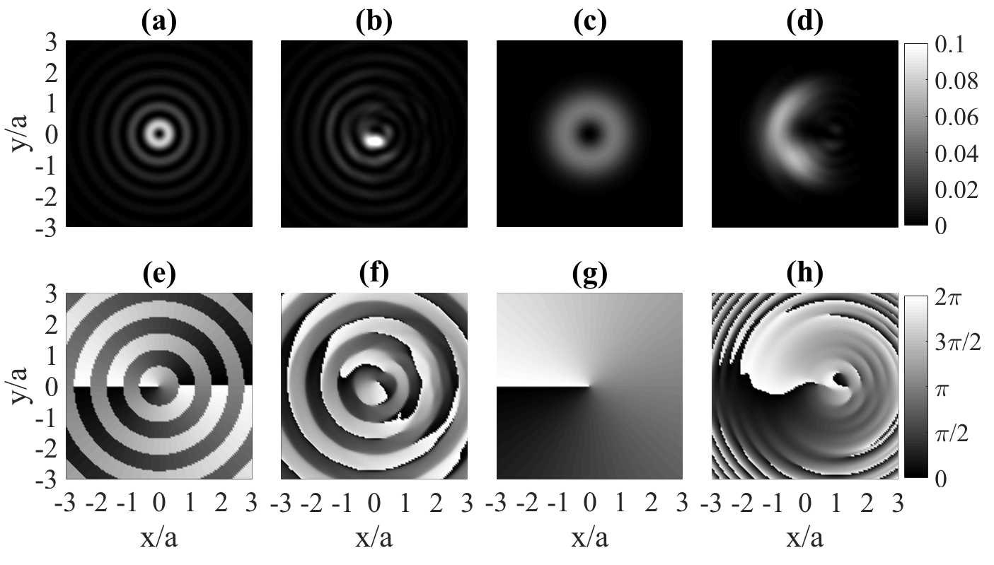
where () indicates the (inverse) Fourier transform in the transverse plane, and , with and wave numbers in the and directions, is the angular-spectrum transfer function Goodman (1968). The resulting intensity (upper) and phase (lower row) distributions for diffracted BG (second) and LG (fourth column) modes with azimuthal index are presented in Fig. 1, in comparison to those of the incident BG (first) and LG (third column) modes.
Clearly, the obstacle significantly perturbs both types of input modes. However, both, the intensity and the phase distributions of the BG mode are less affected by the obstruction than those of the LG mode. This enhanced stability of BG modes is known Bouchal et al. (1998) and attributed to their “healing” property (which LG modes with lack), that is the feature to restore their spatial structure following disturbances. It is worth pointing out that the concept of self healing is not quantitative and purely based on a visual inspection of a finite region around the beam axis. The effect of the obstacle is still present in the transverse plane, but it has been pushed away from the observation window. This is easy to understand if we think of BG modes as superpositions of waves propagating on a cone.
A modification of the intensity and phase distributions of diffracted modes as observed in Fig. 1 can be regarded as the manifestation of diffraction-induced coupling of the spatial modes of the incident wave to other spatial modes. In other words, the diffracted mode (6) corresponds to a normalized single photon diffracted state
| (8) |
for the LG mode, and to
| (9) |
for a BG mode, with and single photon states of the modes and , respectively. The latter, unperturbed mode functions are known exactly Allen et al. (1992); Gori et al. (1987), but they can also be easily assessed numerically, by plugging Eqs. (2) and (3) into the angular-spectrum propagator (7). From Eqs. (8) and (9) it is clear that diffraction introduces crosstalk among different OAM modes Anguita et al. (2008); Tyler and Boyd (2009). The expansion coefficients are then given by the inner products of the diffracted field and the unperturbed mode functions,
| (10a) | |||||
| (10b) | |||||
We point out that the inner products (10) are invariant under translations along the -axis. This can be proven Chu and Wen (2014) using the Plancherel theorem Goodman (1968) and the fact that the -propagation is determined only by the angular-spectrum transfer function [see Eq. (7)]. Therefore, henceforth we will omit the -dependence of the expansion coefficients.
A standard way to analyze crosstalk is through the assessment of the expansion coefficients in Eq. (10). However, even without addressing the individual coupling amplitudes , , we can build some qualitative understanding of the presence of different OAM modes in the diffracted wave. In the next section we will see how the scattering of the input mode into a superposition of many OAM modes induces a non zero mutual overlap of the diffracted waves, and thereby affects the output state entanglement.
Let us therefore examine the bottom row of Fig. 1 where the phase profiles of the incident (azimuthal index ) and diffracted (in general, arbitrary -values) waves are depicted. We identify the character of the incident modes in Figs. 1(e) and (g) by their only phase singularity at the origin, associated with a topological charge one. Inspection of the phase profile of the diffracted beam shows that, notwithstanding some phase distortions, the diffracted BG mode [Fig. 1(f)] still exhibits the very sole phase singularity at the origin. This suggests that the azimuthal index is almost preserved, or that scattering to other OAM modes is weak. In contrast, the appearance of multiple phase singularities for the diffracted LG mode – for example, along the positive axis – is evident [Fig. 1(h)]. This suggests that this phase structure belongs to a superposition of multiple OAM modes.
IV Diffraction of a biphoton on two opaque screens
We can now import our above results for the diffraction of a single input mode, to quantify the entanglement decay of an OAM bi-photon input state when each photon is diffracted upon an obstacle.
While this scenario is inspired by the experiment in McLaren et al. (2014), the physics here considered is different inasmuch as the experiment quantified the output state entanglement as a function of the distance between obstacle (centered at the optical axis) and detector. For distances smaller than the self-healing length of the encoding BG modes, measurement noise obscures the output state entanglement in (McLaren et al., 2014). In contrast, in our present set-up the distance between obstacle and detector is invariant, and we instead quantify entanglement reduction induced by transverse displacements of the obstacle, which leads to non trivial scattering into different OAM modes upon transmission. Therefore, the here observed entanglement reduction is due to an actual perturbation of the transmitted state rather than to a smooth modulation of the signal to noise ratio.
IV.1 Setup

More specifically, we consider the setting in Fig. 2: A source generates pairs of single photon excitations of LG or BG modes, which are Bell state (i.e., maximally) entangled in their OAM,
| (11) |
with the shorthand notation for either (LG mode) or (BG mode). To minimize the notational overhead, we assume that each of the photons is diffracted by a circular screen, and that both screens have identical radii and are placed with opposite offsets with respect to the optical axis. For simplicity and without loss of the essential physics, in our calculations we set both screens at .222Finite distances would lead to the appearance of -dependent propagation phases (see Sec. III.3) in the obstacle plane, resulting, e.g., in rotation of the phase distributions in Fig. 1(e,g). However, this rotation does not affect entanglement. Finally, the biphoton state is calculated at a distance from the obstacle planes.
Under the transformation (4) of each of the modes acting as carriers of the single photon components of the twin-photon state (11), the input state’s underlying mode structure is mapped on the (normalized, according to Eq. (6)) diffracted output mode
| (12) | |||||
where [ and ] represents the constituent single modes’ diffractive image (at the distance from the obstruction). Accordingly, by generalization of Eqs. (8,9), the diffracted bi-photon output state reads
| (13) |
for OAM encoding in the LG (first line) or in the BG (second line) basis, respectively. where the first and second lines correspond to the expansion in the LG and BG bases, respectively, and the dependence on in the right hand side of Eq. (13) is incorporated solely in the basis states. The latter dependence, however, cannot affect entanglement, which is encoded in the expansion coefficients. Thus, entanglement remains invariant under -translations. Therefore, we can lighten the notation and drop the propagation distance in all subsequent expressions.
IV.2 Entanglement of the output state
Given the above, we can now proceed to quantify the diffracted bi-photon output state’s entanglement, directly from its transverse position representation (12). For this purpose we employ the higher dimensional generalization Rungta et al. (2001); Guo et al. (2013) of concurrence Wootters (1998)
| (14) |
where is the reduced density matrix of either one of the entangled photons, after tracing out the other. This trace is performed on the output state’s two photons density matrix
| (15) |
by integration over the transverse coordinates of the second photon, to obtain
| (16) | ||||
In (16) we introduced the (real) parameter,
| (17) |
which is the mutual overlap between the diffracted fields and . Scattering of the input fields into superpositions of OAM modes (see Fig. 1) results in a nonzero value of if and only if some of the modes in the diffracted fields are common. By virtue of Eq. (17), , with the upper bound attained in the degenerate limit , where, however, reduces to a product state.

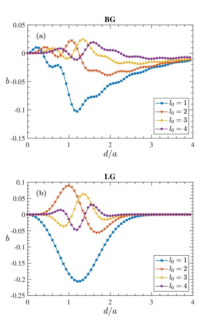
Several examples of the mutual overlap as a function of the relative displacement are shown in Fig. 3. We first note that if . In this case, the mutual overlap vanishes, since the perturbation caused by the obstacle leaves the cylindrical symmetry of diffracted waves intact. Furthermore, when the screens’ displacement is large compared to the essential support of the beam, due to the trivial reason that the screens’ impact turns negligible in this limit. For intermediate displacements of the obstructions, interference of the diffracted modes results in oscillations of , with amplitudes which are smaller for BG than for LG encoding, for a given , and progressively decrease with increasing OAM, for both sets of modes. One can see a progression in the oscillation of the mutual overlap in the LG case. The number of peaks and dips is equal to the OAM index (see also Sec. IV.4). The oscillations are modulated by an envelope function, whose amplitude and width gradually decrease with increasing . In the case of , the dip in the oscillation more or less coincides with the peak of the envelope function. Therefore its amplitude seems disproportionately large compared to those for higher orders. In the BG case, the shapes of the curves are more complex. There are still oscillations, but their modulation is more irregular. Nevertheless, a similar progression causes the amplitudes of these curves to decrease gradually for increasing .
The significance of the mutual overlap is that it uniquely determines the diffraction-induced entanglement decay. Indeed, using the normalization of , as well as Eqs. (16) and (17), we find
| (18) | ||||
which leads to an explicit expression for the output state’s concurrence (14), as the main result of this work:
| (19) |
However, is not an independent parameter but a function of the beam waist, of the size and displacement of the screen, and of the azimuthal index.
IV.3 Entanglement loss upon diffraction
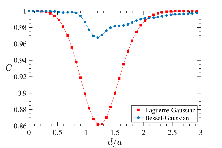
Let us now assess the entanglement decay featured by the diffracted image of (11) – for encoding in . This is the case for which we have the maximum mutual overlap (see Fig. 3). Fig. 4 shows the dependence of on the relative displacement . Comparison to Fig. 3 shows that the behaviour of follows directly from that of (see Fig. 3), and that, in particular, OAM entanglement is more robust in the BG as compared to the LG basis, for most values of . Only for large displacements does LG offer a tiny advantage, since the multi-ring intensity profile of BG modes leads to some residual overlap even at large . This multi-ring structure is also at the origin of the modulation of the BG mode’s output concurrence with the displacement, and of the underlying mutual overlap behaviour depicted in Fig. 3(a). Minimal output concurrence is observed, for both encodings, at , corresponds to stationary points of the mutual overlap in Fig. 3, and is due to the obstacles’ overlaps with the maxima of the intensity distribution of the input beams (e.g., the LG input mode with and has an intensity maximum concentrated along a single ring with radius , and exhibits a minimum precisely when the obstacle is placed at the corresponding position).
IV.4 Entanglement and the phase correlation length
The situation is slightly more complicated for LG-encoded OAM entangled input states (11) with . While an LG mode’s intensity profile exhibits only one bright ring also for , the mutual overlap oscillates, as shown in Fig. 3(b), and so does the output concurrence in Fig. 5, due to (19). We therefore need to resort to the output state’s phase distribution, and, in particular, to its phase correlation length Leonhard et al. (2015), which accounts for both, its phase and intensity profiles.
For LG modes with and , reads Leonhard et al. (2015)
| (20) |
and it was shown that the entanglement decay experienced by LG-encoded OAM entangled states in a weakly turbulent atmosphere is a universal function of the ratio , where is the turbulence coherence length (the typical length scale on which turbulence-induced phase errors are correlated Fried (1965)). In our present scenario, a natural analog of is the radius of the obstacle, and the curves in Fig. 5 are obtained for distinct values of the ratio for each of the panels (a-c). While there is no apparent regularity of the behaviour of in either one of the panels (a-c), the results can be classified by one specific feature – the number of minima of . To demonstrate this, panel (d) correlates with the ratio : Indeed, for small values , , and with increasing , steadily decreases by one, at and .
V Conclusion
In this work, we studied the effect of the diffraction of a singlet type biphoton OAM state, initially encoded either in LG or in BG modes, on the entanglement content of such states. Using methods of Fourier optics we inferred the diffracted twin-photon state, taking into account the size and shift of the obstacle with respect to the beam axis, as well as different initial azimuthal quantum numbers of the modes.
We derived an analytical formula for the concurrence of the diffracted state, which is an infinite dimensional, pure state. This formula depends only on one parameter – the scattering-induced mutual overlap between the two diffracted waves which stem from the OAM modes with indices and , respectively. This result, in particular, shows that peculiarities of spatial distributions of BG and LG modes lead to different mutual overlaps of diffracted waves, which, eventually, results in stronger robustness of entanglement for BG modes. Thereby, our theoretical findings complement the experimental observations of McLaren et al. (2014).
This work corroborates that scattering into superpositions of OAM modes underlies the behavior of entanglement under deterministic perturbations, such as diffraction, as much as it does under random disturbances, such as weak atmospheric turbulence Leonhard et al. (2015). Therefore, our results suggest a stronger resilience in atmospheric turbulence of photonic OAM entanglement encoded into BG than into LG modes – a statement which will be interesting to verify in the future. Another possible research direction will be to interpret the diffraction-induced spreading of the OAM spectrum in terms of the uncertainty principle for angular position and angular momentum Franke-Arnold et al. (2004) and to establish a connection between angular uncertainty and OAM entanglement loss.
Acknowledgements.
We would like to thank A. Forbes for illuminating and enjoyable discussions. G.S., V.N.S. and A.B. acknowledge support by Deutsche Forschungsgemeinschaft under grant DFG BU 1337/17-1.References
- Andrews and Babiker (2013) D. Andrews and M. Babiker, The Angular Momentum of Light (Cambridge University Press, 2013).
- Krenn et al. (2014) M. Krenn, M. Huber, R. Fickler, R. Lapkiewicz, S. Ramelow, and A. Zeilinger, Proc. Natl. Acad. Sci. U.S.A. 111, 6243 (2014).
- Wang et al. (2012) J. Wang, J.-Y. Yang, I. M. Fazal, N. Ahmed, Y. Yan, H. Huang, Y. Ren, Y. Yue, S. Dolinar, M. Tur, and A. E. Willner, Nat. Photon. 6, 488 (2012).
- Mafu et al. (2013) M. Mafu, A. Dudley, S. Goyal, D. Giovannini, M. McLaren, M. J. Padgett, T. Konrad, F. Petruccione, N. Lütkenhaus, and A. Forbes, Phys. Rev. A 88, 032305 (2013).
- Mirhosseini et al. (2015) M. Mirhosseini, O. S. Magaña-Loaiza, M. N. O’Sullivan, B. Rodenburg, M. Malik, M. P. J. Lavery, M. J. Padgett, D. J. Gauthier, and R. W. Boyd, New J. Phys. 17, 033033 (2015).
- Anguita et al. (2008) J. A. Anguita, M. A. Neifeld, and B. V. Vasic, Appl. Opt. 47, 2414 (2008).
- Tyler and Boyd (2009) G. A. Tyler and R. W. Boyd, Opt. Lett. 34, 142 (2009).
- Smith and Raymer (2006) B. J. Smith and M. G. Raymer, Phys. Rev. A 74, 062104 (2006).
- Roux (2011) F. S. Roux, Phys. Rev. A 83, 053822 (2011).
- Hamadou Ibrahim et al. (2013) A. Hamadou Ibrahim, F. S. Roux, M. McLaren, T. Konrad, and A. Forbes, Phys. Rev. A 88, 012312 (2013).
- Leonhard et al. (2015) N. D. Leonhard, V. N. Shatokhin, and A. Buchleitner, Phys. Rev. A 91, 012345 (2015).
- Roux et al. (2015) F. S. Roux, T. Wellens, and V. N. Shatokhin, Phys. Rev. A 92, 012326 (2015).
- McLaren et al. (2014) M. McLaren, T. Mhlanga, M. J. Padgett, F. S. Roux, and A. Forbes, Nat. Commun. 5 (2014).
- Goodman (1968) J. Goodman, Introduction to Fourier Optics (McGraw-Hill, 1968).
- Allen et al. (1992) L. Allen, M. W. Beijersbergen, R. J. C. Spreeuw, and J. P. Woerdman, Phys. Rev. A 45, 8185 (1992).
- Mair et al. (2001) A. Mair, A. Vaziri, G. Weihs, and A. Zeilinger, Nature 412, 313 (2001).
- Gori et al. (1987) F. Gori, G. Guattari, and C. Padovani, Opt. Commun. 64, 491 (1987).
- Durnin et al. (1987) J. Durnin, J. J. Miceli, and J. H. Eberly, Phys. Rev. Lett. 58, 1499 (1987).
- Durnin (1987) J. Durnin, J. Opt. Soc. Am. A 4, 651 (1987).
- Bouchal et al. (1998) Z. Bouchal, J. Wagner, and M. Chlup, Opt. Commun. 151, 207 (1998).
- Bouchal (2002) Z. Bouchal, Opt. Commun. 210, 155 (2002).
- Litvin et al. (2009) I. A. Litvin, M. G. McLaren, and A. Forbes, Opt. Commun. 282, 1078 (2009).
- McLaren et al. (2012) M. McLaren, M. Agnew, J. Leach, F. S. Roux, M. J. Padgett, R. W. Boyd, and A. Forbes, Opt. Express 20, 23589 (2012).
- Fischer et al. (2007) P. Fischer, S. E. Skelton, C. G. Leburn, C. T. Streuber, E. M. Wright, and K. Dholakia, Opt. Express 15, 11860 (2007).
- Chu and Wen (2014) X. Chu and W. Wen, Opt. Express 22, 6899 (2014).
- Rungta et al. (2001) P. Rungta, V. Bužek, C. M. Caves, M. Hillery, and G. J. Milburn, Phys. Rev. A 64, 042315 (2001).
- Guo et al. (2013) Y. Guo, J. Hou, and Y. Wang, Quantum Inf. Process. 12, 2641 (2013).
- Wootters (1998) W. K. Wootters, Phys. Rev. Lett. 80, 2245 (1998).
- Fried (1965) D. L. Fried, J. Opt. Soc. Am. 55, 1427 (1965).
- Franke-Arnold et al. (2004) S. Franke-Arnold, S. M. Barnett, E. Yao, J. Leach, J. Courtial, and M. Padgett, New J. Phys. 6, 103 (2004).