Thermal management and non-reciprocal control of phonon flow via optomechanics
Abstract
Engineering phonon transport in physical systems is a subject of interest in the study of materials, and plays a crucial role in controlling energy and heat transfer. Of particular interest are non-reciprocal phononic systems, which in direct analogy to electric diodes, provide a directional flow of energy. Here, we propose an engineered nanostructured material, in which tunable non-reciprocal phonon transport is achieved through optomechanical coupling. Our scheme relies on breaking time-reversal symmetry by a spatially varying laser drive, which manipulates low-energy acoustic phonons. Furthermore, we take advantage of developments in the manipulation of high-energy phonons through controlled scattering mechanisms, such as using alloys and introducing disorder. These combined approaches allow us to design an acoustic isolator and a thermal diode. Our proposed device will have potential impact in phonon-based information processing, and heat management in low temperatures.
Introduction
Controlling the flow of heat is important for several fields including thermoelectrics, thermal management, and information processing. For example, suppressing thermal conductivity can improve the performance of thermoelectrics, and can also isolate circuit elements from external heat. The thermal analog of an electric diode is of fundamental importance to efforts in managing heat. Thermal diodes have numerous applications, including blocking unwanted backscattering in phonon-based information processing as well as managing heat and maximizing efficiency in nanostructures. The operation of a thermal diode requires a nonlinear material or broken time-reversal symmetry Maznev2013 ; most implementations have exploited the former terraneo2002controlling ; Li2004 ; segal2005spin ; Majumdar06 ; yang2007thermal .
Theoretical and experimental advances in our understanding of the contribution of coherent phonons to heat transport has provided new insights that allow for enhanced control of heat flow in nanostructured materials Maldovan15 . Specifically, due to the very long mean free paths and coherence of these phonons luckyanova2012coherent ; esfarjani2011heat , periodic structures can modify their dispersion and transport properties Maldovan13 . Thus, engineered band-gaps, which have been used to manipulate sound li2012colloquium , can also be used to alter the thermal properties of a material hopkins2010reduction . Moreover, adding impurities have been proven useful in modifying thermal transport properties of a material by manipulating high-energy phonons kim2006thermal ; snyder2008complex .
At the same time, there have been remarkable advances in cavity optomechanics Aspelmeyer2014 , where interactions between photons and acoustic phonons confined in an optomechanical cavity can be controlled at the single phonon level chan2011laser , with potential applications in quantum information processing stannigel2012optomechanical ; habraken2012continuous . More recently, non-reciprocal optical transport was proposed in ring resonators, where the directional laser pump selects one circulation direction hafezirabl2012 . This scheme and approaches based on stimulated Brillouin scattering in photonics NonrecHuang2011 ; NonrecKang2011 were experimentally demonstrated in multiple optomechanical systems NonrecKim2015 ; NonrecDong2015 ; shen2016experimental ; alu2016nonreciprocity ; fang2016generalized . Meanwhile, the resulting chirality for phonons in such ring-resonators has been investigated Alu2014sound ; bahl2016dynamically ; jake2017optomechanically . Moreover, there have been intriguing proposals to synthesize gauge fields in optomechanical systems, from photonic crystals Marquardt13 ; Marquardt15 , to quantum wells Sasha2017 , and superconducting circuits Shabir2017manipulating , and to investigate their associated topological properties peano2015topological .
In this article, we combine the physics of heat transport in nanostructures and optomechanics to develop a new platform to manipulate both low- and high-energy phonons. We propose a method to engineer a tunable non-reciprocal band-gap for acoustic phonons, where a laser field with a phase gradient optically drives an array of optomechanical cavities and induces the non-reciprocal transport by breaking the time-reversal symmetry. We propose an experimental implementation of the scheme in optomechanical crystals. We discuss two applications of such a system, one as an acoustic isolator, and the other as a thermal diode. For the latter, the introduction of alloy and nanoparticle disorder suppresses the transport of high-energy phonons, leaving the low-energy acoustic band as the dominant channel for heat conduction Marzari11 ; Maldovan13 , thus enhancing the overall optomechanically induced non-reciprocity. Our proposed device works in the linear regime and introduces an alternative approach to previous works.
Results
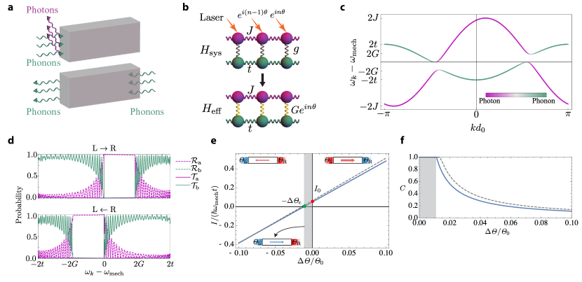
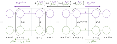
Tight-binding model To illustrate the basic concepts, we study non-reciprocal transport in a system connected to heat baths. The system considered here is described by a tight-binding model of an array of coupled optomechanical cavities Hafezi2011 ; Aashish14 ; rakich2016quantum . An optomechanical cavity supports localized electromagnetic and mechanical modes. Due to radiation pressure, changes to the shape of the cavity change its electromagnetic resonance frequency, effectively coupling mechanical vibrations to electromagnetic excitations. The Hamiltonian describing a collection of isolated cavities (setting ) is
| (1) |
where is a bosonic operator that destroys a photonic (phononic) excitation with energy at site , and is the vacuum coupling rate. In addition, there is a loss rate associated with the optical (mechanical) mode of the cavity (see Methods).
In a linear array of cavities, nearest-neighbor couplings dominates due to the tunneling of excitations between adjacent sites. The Hamiltonian describing these processes is
| (2) |
where h.c. denotes Hermitian conjugate, and and are tunneling strengths of phononic and photonic excitations, respectively. The system Hamiltonian is then given by
| (3) |
The vacuum coupling rate, , is typically small, and can be enhanced by means of an external laser drive. To break reciprocity in a spatially dependent manner, in contrast to the usual setup in which the optical mode on each site is excited by a laser with a uniform phase Aspelmeyer2014 , we consider a phase gradient in the laser field. This phase, which breaks time-reversal symmetry introduces a position dependent phase in the effective coupling between phonons and photons Marquardt15 . The breaking of time-reversal symmetry is crucial for the effects we consider in this work. The laser frequency, , is detuned from the resonance frequency of the cavity by , and the phase offset between adjacent sites is , as shown in Fig. 1(b).
In order to bring electromagnetic and mechanical excitations on resonance, the driving laser is red-detuned from the cavity resonance frequency by . In a rotating frame of photons with angular frequency , after making the rotating-wave approximation (RWA) in the resolved sideband regime (), linearizing and displacing the cavity field, the effective Hamiltonian is aspelmeyer2014cavity
| (4) | ||||
where , the enhanced optomechanical coupling strength is large compared to by an order of , the square root of the number of photons in the cavity.
The propagating modes of the system are polaritons, which are superpositions of electromagnetic and mechanical quanta. In order to diagonalize the Hamiltonian in equation (4), we write the Fourier transform for and as
| (5) |
where is the lattice constant. Then equation (4) in the Fourier basis is
| (6) |
which shows the phase gradient of the laser field acts as a momentum shift, and leads to the coupling of phonons and photons with different momenta.
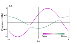
The band structure is shown in Fig. 1(c). In the absence of coupling the phononic and photonic dispersions intersect. For , two band-gaps develop. The asymmetry (under ) of the band structure is controlled by . The eigenmodes are polaritons, , where is the band index. The quantities and indicate the relative weights of photons and phonons composing the polaritons, respectively. The effect of cavity loss is to broaden the bands, and for the gaps to be effective, we need to be in the high cooperativity regime, i.e. .
The asymmetry of the gaps controls the non-reciprocal transport properties of the system, as shown Fig. 1(d). In order to study thermal transport properties of this model, we consider connecting the system to two thermal contacts. The contacts are impedance matched to the non-driven () system. Thus, the dispersion of phonons in the contacts is . The transmission probabilities can be calculated by mode matching at the boundaries of the system; see Fig. 1(d) and the Supplementary Note 1. This continuum picture remains valid for a finite number of lattice sites and the transmission probabilities are close to zero for phonons with energies in the gap. These phonons are converted to photons and reflected. The probabilities exhibit Fabry-Perot oscillations whose period is proportional to the inverse of the number of sites in the system. The direction dependent phonon transmission probability for close to can be approximated by
| (7) |
where is the Heaviside step function.
The phonon thermal current, assuming that the photon contacts are at zero temperature, can be calculated in the Landauer-Büttiker formalism yang2012thermal ; datta1996scattering , and is given by
| (8) | ||||
where is the temperature of the left(right) contact, and . We introduce an alternative set of variables to denote the mean temperature, , and the temperature bias, , such that
| (9) |
with
| (10) | ||||
| (11) |
This relationship implies that if is fixed and only the sign of is changed, the temperatures of the two contacts are swapped. In a reciprocal system there is no distinction between left and right, and taking only changes the sign of the current and leaves the magnitude unchanged. However, due to the broken time-reversal symmetry in our system, transport is non-reciprocal , and the current magnitudes are different. Fig. 1(e) shows the current as a function of temperature bias . The base temperature is chosen close to the energy scale of the system, so that the non-reciprocal effect is enhanced. In this plot, the non-zero intercept () is a measure of the non-reciprocity. This is different from an electrical diode mechanism, where the slope changes as the bias is reversed.
To quantify the non-reciprocity, we introduce the contrast , defined as
| (12) |
which is non-zero in a non-reciprocal system. In the shaded region in Fig. 1(e) and (f) the current doesn’t change its direction when the bias is reversed. In this case the contrast is maximized and .
The relation between and for , and is well described by
| (13) |
In the same regime, the contrast is given by
| (14) |
where . These approximations are compared with the exact values in Fig. 1(e) and (f).
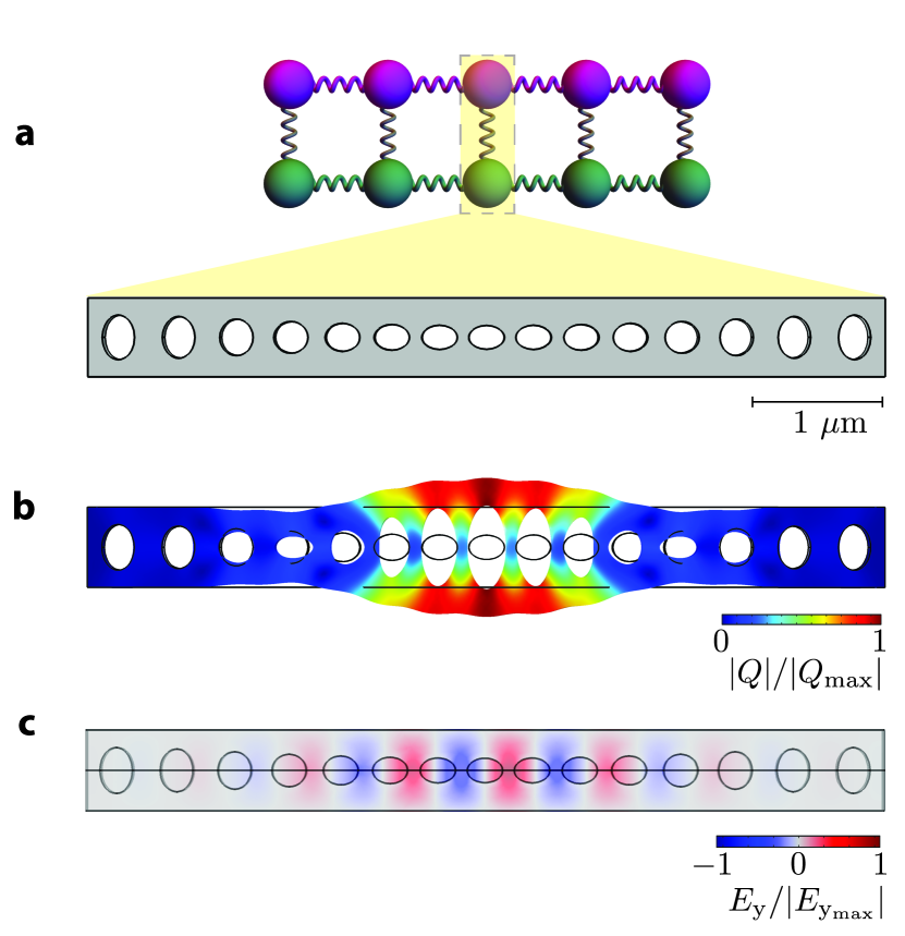
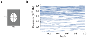
This non-reciprocal model can be implemented in an optomechanical crystal chan2012laser ; safavi2014optomechanical . An optomechanical crystal is an engineered dielectric which supports localized phononic and photonic excitations with energies in the band gaps. Given a uniform dielectric, band gaps can be introduced by drilling a periodic array of identical holes. Deforming these holes to form a superlattice introduces defect cavities which co-localize phonons and photons, thereby enhancing their mutual couplings. In Fig. 2, we show the correspondence between a cavity and its implementation in the actual optomechanical crystal. Each unit cell is a few microns in size, and a total system size of hundreds of microns leads to the nonreciprocity shown in Fig. 1(d). The bare optomechanical coupling varies between several kilohertz and tens of megahertz in various materials such as Si or GaAs Balram14 ; fang2016generalized ; Lejssen17 . The tunneling strengths depend on the structure design, and values of a few megahertz for the mechanical tunneling strength , and hundreds of megahertz for its optical counterpart, have been realized in the experiments fang2016generalized . In Methods and Supplementary Note 2, we present more details, and specifically show how to engineer the non-reciprocal band in an optomechanical crystal. The tight-binding model is applicable not only to optomechanical crystal arrays, but also to other optomechanical systems such as coupled ring resonators that have been realized in experiments favero2017 .
Applications Now that we have established that non-reciprocal transport for a continuum band of phonons can be achieved in an array of optomechanical cavities, we further discuss two applications in an optomechanical crystal (see Methods): (1) An acoustic isolator, and (2) a thermal diode in low temperatures.
An acoustic isolator is a device that only permits propagation of coherent monochromatic phonons in one direction. Such a device can be realized using a nonlinear medium attached to a phononic crystal liang2009acoustic ; liang2010acoustic , or through spatio-temporal modulation of system properties in a transmission line Zanjani2015 . Our optomechanical crystal operates as an isolator for frequencies which lie in the bandgap. An appropriate figure of merit analogous to the contrast in equation (12) for monochromatic waves is
| (15) |
The device discussed in the previous section, with the same red detuned laser drive acts as an isolator for phonons with frequencies close to . Specifically, in the high cooperativity regime, the effect of loss is negligible, and we can use the transmission probabilities shown in Fig. 1(d). We see that for propagating elastic waves with frequencies inside the band gap, approaches unity, and otherwise, is very close to zero, thus realizing an isolator with a bandwidth of . The non-reciprocity in our scheme is tunable, and the frequency range of the gap is also controllable and depends on the phase gradient of the laser field. Furthermore, since the Hamiltonian in equation (4) is linear in both the optical and mechanical fields, in principle the device works at the quantum limit. It is therefore useful for quantum information routing habraken2012continuous , and may find new applications to hybrid devices such as superconducting qubits clarke2008superconducting coupled to optomechanical crystals stannigel2012optomechanical , as they both work in the same energy regime.
As a second application, we show that our system can serve as a thermal diode. A perfect thermal diode would allow heat transport in only one direction. Our system relies on the modification of the material properties in a narrow frequency range at low energies, while a major part of heat current is carried out by high-frequency phonons. To suppress the contribution of these high-energy phonons we introduce various scattering mechanisms to shorten their mean free paths Maldovan13 .
Specifically, to evaluate the figure of merit in a realistic material, we analyze frequency dependent phonon scattering processes characterized by a length scale . The total transmission at a given frequency, summed over all bands, can be approximated as
| (16) |
where the factor is the probability of transmittance jeong2012thermal ; datta1997electronic , and is the number of conducting bands at a given energy for right (), or left () moving phonons, and is the sample’s porosity. The function comes from Maxwell-Garnett effective medium approach, and takes the effect of holes on the number of modes into account nan1997effective ; alaie2015thermal . The parameter is the length of the sample, and is the mean free path of back scattering, which is related to the mean free path of scattering, , by in 1D, and in 3D. Note that because of the dependence of on frequency, the performance of the device gets better for larger samples. Specifically, for larger samples the overall transmission decreases, however, since the mean free path is smaller for higher frequencies, the contrast improves. In our calculations, we considered N=100 sites.
Following refs. mingo2009nanoparticle ; Maldovan13 , we propose using alloy and nano-paricle impurities to modify . In this case, the optomechanical crystal is made of an alloy into which nanoparticles are embedded. These impurities lead to mass-difference scatterings, and their respective rates and scales with , thus lowering the contribution of high-energy phonons and increasing the contribution of low-energy phonons to thermal transport. To obtain a realistic estimate of , it is necessary to consider two additional scattering mechanisms: intrinsic anharmonicity and boundary scattering, characterized by rates and , respectively. The corresponding mean free paths ’s, are obtained from the scattering rates by , where is the group velocity. The total mean free path is given by Matthiessen’s rule, i.e.,
| (17) |
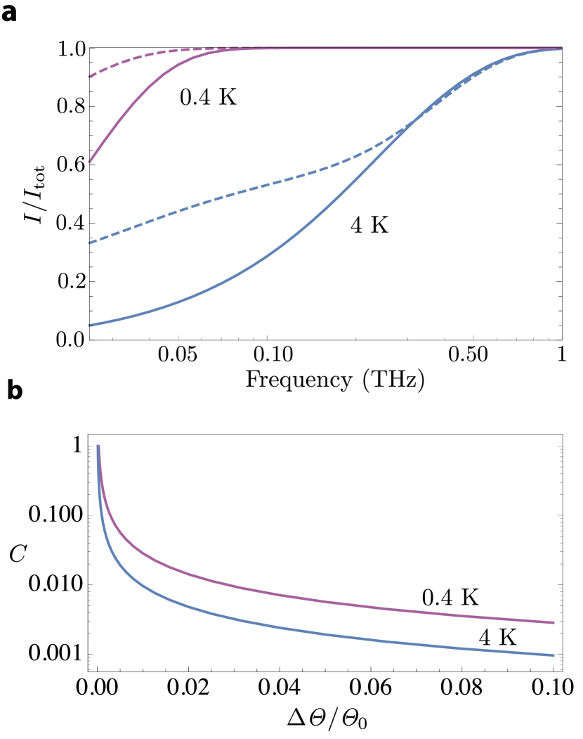
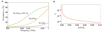
The effect of these scattering mechanisms on the cumulative thermal current, shown in Fig. 3(a), is evaluated by a hybrid method using the bulk silicon dispersion () for high-energy phonons with short mean free paths and the superlattice dispersion for lower energy phonons with mean free paths longer than several lattice constants of the superlattice alaie2015thermal (see Methods). It can be seen that phonons with frequencies below 25 GHz contribute more to heat transport in a optomechanical crystal with 10 nm nano-particles and a filling factor of 5% than to a nanobeam of the same dimensions composed of nonporous silicon. Moreover, the ratio of the current carried by the optomechanically coupled band to the total current in the engineered optomechanical crystal is close to 9% at 4 K and about 22% at 0.4 K with a bias of . (see Supplementary Note 3).
Finally, we calculate the contrast for a driven optomechanical crystal, as displayed in Fig. 3(b). As the base temperature decreases and approaches the energy of the optomechanical band (), the contrast and the non-reciprocal effect increase. While a significant constrast can be achieved at sub-Kelvin temperatures, the generalization of this scheme to room temperature requires a significant improvement in the material properties such as the optomechanical coupling strength (see Supplementary Note 3 for room temperature). Although there is intrinsic photon loss in the silicon beam, such loss does not directly lead to the generation of phonons in the beam meenehan2014silicon , and therefore, the implicit assumptions of our approach remain valid. (see Methods and Supplementary Note 3).
To measure the contrast, we envision a setup similar to Ref. zen2014engineering , where a pair superconductor/insulator/normal metal/insulator/superconductor (SINIS) tunnel junction giazotto2006opportunities are mounted at the two ends of the device and serve as both a sensitive thermometer and a heater. The device is heated from one side and the change in temperature is measured at the other side. By interchanging the role of the heater and thermometer and comparing the measurements, the existence of non-reciprocal thermal current in the system can be verified.
Discussion
In this work, we have shown that phase-modulated driven optomechanical systems can be utilized to engineer a non-reciprocal phonon band in a material. We discussed two possible applications of our scheme, as an acoustic isolator and a thermal diode. While we considered a specific silicon-based optomechanical crystal, these methods can be readily generalized to other materials and designs. These devices may find application to on-chip heat management and quantum information processing, both to increase coherence time and to exploit phonons as information carriers chu2017quantum .
In our approach, we proposed a coherent dynamical control of low-energy phonons by using optomechanical structures, and combined it with incoherent control of high-energy phonons by designing bulk material properties through the introduction of disorder. This strategy of combing low- and high-energy phononic physics could be generalized to designing of other thermal technologies such as thermoelectrics, thermal insulation, and the development of new metamaterials.
METHODS
Implementation with optomechanical crystals
In an optomechanical cavity electromagnetic and mechanical modes are co-localized. The coupling between these modes arises due to radiation pressure, which changes the cavity’s electromagnetic resonance frequency. More rigorously, the energy of a cavity depends on its shape, where is the quantized mechanical displacement, and denotes zero point fluctuations. The Hamiltonian describing a single defect cavity is
| (18) |
The optomechanical coupling arises as the shape of the dielectric boundary changes. Expanding to first order in results in
| (19) |
where can be calculated from moving boundaries perturbation theory for Maxwell’s equations johnson2002 ; Eichenfield09 . Equation (19) reproduces the form of (1).
Imperfect localization within each cavity leads to nearest-neighbor hopping of the phonons and photons as captured by (4). Using finite element simulations (FEM), we find that to a very good approximation these bands follow the dispersion as predicted by the tight-binding model (see Supplementary Note 2). Typical values of , and for a silicon optomechanical crystal are , and , respectivelyfang2016generalized . The laser frequency should be to bring it in resonance with the mechanical mode.
To linearize the Hamiltonian with the laser drive , we solve for the steady-steady of the cavity in the absence of the optomechanical coupling () Aspelmeyer2014 , and find that the steady-state is given by
| (20) |
where is the number of photons in the cavity. Consequently, displacing the cavity field by , and using RWA results in (4).
The phases () can be tuned off the chip by using stretchable fiber phase shifters fang2016generalized . An on-chip implementation is possible by using a multi-mode interferometer to divide the power, and meandered waveguides or zero-loss resonators to tune the phase (see Supplementary Note 4).
Scattering rates
The scattering rate associated with the alloy disorder of is described by an effective mass-difference Rayleigh scattering klemens1955scattering ; abeles1963lattice
| (21) |
where mingo2009nanoparticle ; Maldovan13 is a constant that depends on the alloy properties. Scattering due to nanoparticles can be described by interpolating between the long and short wavelength scattering regimes kim2006phonon ; mingo2009nanoparticle ,
| (22) |
where and are the filling fraction and the volume of nanoparticles, is the magnitude of the group velocity of phonons, and
| (23) | ||||
| (24) |
Here, is the radius of nanoparticles, is the difference between particle and alloy densities, and is the alloy’s density. In our calculations, we consider a filling fraction of , , and , corresponding to nm germanium nanoparticles in .
The anharmonic scattering rate, which takes both the normal and umklapp processes into account, is given by
| (25) |
where and K for mingo2009nanoparticle ; Maldovan13 . Scattering from the boundaries of a thin film can be modeled by ziman1960electrons ; sondheimer1952mean , where , the thickness of the sample, is the mean free path in the diffusive limit. The parameter is the probability that the scattering is specular. It takes the effect of surface roughness into account and depends on the phonon’s wavelength. It is given by ziman1960electrons ; zhang2007nano
| (26) |
where is the wavelength of the phonons, and is the surface roughness of the sample, which is taken to be 1 nm in our calculations, and corresponds to an estimated surface roughness achieved in silicon thin film fabrications jeong2012thermal .
Thermal current
In Fig. 3, we compared the operation of our optomechanical crystal with a nanobeam of nonporous silicon. The thermal current in the latter can be calculated as follows. At the temperatures considered, only phonons with frequencies smaller than 3 THz are relevant for thermal transport. In this frequency range, only the acoustic branch contributes to thermal conductivity and the dispersion is approximately linear. Specifically, we employed the Debye dispersion, i.e. , where is the sound velocity, and k is the wavevector. The density of modes is given by , where is the cross sectional area. In addition, because the sample in this case is nonporous, , and the only scattering mechanisms are scatterings due to surface roughness and crystal anharmonicities.
The thermal current for the proposed optomechanical crystal with nano-particles is calculated using a hybrid method, depending on the frequency of phonons alaie2015thermal . Specifically, The mean free path of phonons depends on their frequency. As the frequency of phonons is lowered, their mean free path becomes comparable with the superlattice spacing, and therefore, the bulk dispersion is no longer a good description. In our system this threshold frequency corresponds to 25 GHz. In order to get this number, using the silicon bulk dispersion and equations (17) and (21)-(26), we find the frequency for which the mean free path is comparable to several lattice spacings.
For phonons with frequencies above the threshold, we use the bulk Debye dispersion and associated group velocities and density of states. For phonons with frequencies lower than this threshold, we use the superlattice dispersion, calculated by FEM simulations, which gives group velocities and density of states different from those of the bulk. The scattering rates are then calculated using the superlattice dispersion in this regime. Taken together, these account for the total reciprocal phonon contribution to the thermal current. Finally, we add the contribution of the single non-reciprocal optomechanically coupled band to the calculated current. For this single band, we have used and parameters GHz, GHz, GHz, and GHz, which leads to asymmetric gaps in , and for right-going, and left-going phonons, respectively.
Data availability. The data that support the findings of this study are available from the authors upon reasonable request.
Acknowledgments
We thank Krishna Balram for providing the initial FEM simulations, Hirokazu Miyake for helping with the simulations, and Reza Ghodssi for providing access to computational resources. We also thank Sunil Mittal, Raphaël Van Laer, Amir Safavi-Naeini, and Oskar Painter for helpful discussions. The work was partially supported by Sloan Fellowship, YIP-ONR, the NSF PFC at the JQI.
Author Contribution
A.S. and W.D. formulated the transmission probabilities in the tight-binding model. A.S. performed the calculation and numerical simulations. K.E. and M.H. directed the study. All authors discussed and analyzed the results and contributed and commented on the manuscript.
Competing interests
The authors declare no competing interests.
References
- (1) Maznev, A., Every, A. & Wright, O. Reciprocity in reflection and transmission, what is a ‘phonon diode’? Wave Motion 50, 776–784 (2013).
- (2) Terraneo, M., Peyrard, M. & Casati, G. Controlling the Energy Flow in Nonlinear Lattices: A Model for a Thermal Rectifier. Phys. Rev. Lett. 88, 094302 (2002).
- (3) Li, B., Wang, L. & Casati, G. Thermal Diode: Rectification of Heat Flux. Phys. Rev. Lett. 93, 184301 (2004).
- (4) Segal, D. & Nitzan, A. Spin-Boson Thermal Rectifier. Phys. Rev. Lett. 94, 034301 (2005).
- (5) Chang, C., Okawa, D., Majumdar, A. & Zettl, A. Solid-State Thermal Rectifier. Science 314, 1121–1124 (2006).
- (6) Yang, N., Li, N., Wang, L. & Li, B. Thermal rectification and negative differential thermal resistance in lattices with mass gradient. Phys. Rev. B 76, 020301 (2007).
- (7) Maldovan, M. Phonon wave interference and thermal bandgap materials. Nat. Mater. 14, 667–674 (2015).
- (8) Luckyanova, M. N. et al. Coherent Phonon Heat Conduction in Superlattices. Science 338, 936–939 (2012).
- (9) Esfarjani, K., Chen, G. & Stokes, H. T. Heat transport in silicon from first-principles calculations. Phys. Rev. B 84, 085204 (2011).
- (10) Maldovan, M. Narrow Low-Frequency Spectrum and Heat Management by Thermocrystals. Phys. Rev. Lett. 110, 025902 (2013).
- (11) Li, N. et al. Colloquium: Phononics: Manipulating heat flow with electronic analogs and beyond. Rev. Mod. Phys. 84, 1045–1066 (2012).
- (12) Hopkins, P. E. et al. Reduction in the Thermal Conductivity of Single Crystalline Silicon by Phononic Crystal Patterning. Nano Lett. 11, 107–112 (2010).
- (13) Kim, W. et al. Thermal Conductivity Reduction and Thermoelectric Figure of Merit Increase by Embedding Nanoparticles in Crystalline Semiconductors. Phys. Rev. Lett. 96, 045901 (2006).
- (14) Snyder, G. J. & Toberer, E. S. Complex thermoelectric materials. Nat. Mater. 7, 105–114 (2008).
- (15) Aspelmeyer, M., Kippenberg, T. J. & Marquardt, F. Cavity optomechanics. Rev. Mod. Phys. 86, 1391–1452 (2014).
- (16) Chan, J. et al. Laser cooling of a nanomechanical oscillator into its quantum ground state. Nature 478, 89–92 (2011).
- (17) Stannigel, K. et al. Optomechanical Quantum Information Processing with Photons and Phonons. Phys. Rev. Lett. 109, 013603 (2012).
- (18) Habraken, S., Stannigel, K., Lukin, M. D., Zoller, P. & Rabl, P. Continuous mode cooling and phonon routers for phononic quantum networks. New J. Phys. 14, 115004 (2012).
- (19) Hafezi, M. & Rabl, P. Optomechanically induced non-reciprocity in microring resonators. Opt. Express 20, 7672–7684 (2012).
- (20) Huang, X. & Fan, S. Complete All-Optical Silica Fiber Isolator via Stimulated Brillouin Scattering. J. Lightwave Technol. 29, 2267–2275 (2011).
- (21) Kang, M. S., Butsch, A. & Russell, P. S. J. Reconfigurable light-driven opto-acoustic isolators in photonic crystal fibre. Nat. Photonics 5, 549–553 (2011).
- (22) Kim, J., Kuzyk, M. C., Han, K., Wang, H. & Bahl, G. Non-reciprocal Brillouin scattering induced transparency. Nat. Phys. 11, 275–280 (2015).
- (23) Dong, C.-H. et al. Brillouin-scattering-induced transparency and non-reciprocal light storage. Nat. Commun. 6, 6193 (2015).
- (24) Shen, Z. et al. Experimental realization of optomechanically induced non-reciprocity. Nat. Photonics 10, 657–661 (2016).
- (25) Ruesink, F., Miri, M.-A., Alù, A. & Verhagen, E. Nonreciprocity and magnetic-free isolation based on optomechanical interactions. Nat. Commun. 7, 13662 (2016).
- (26) Fang, K. et al. Generalized non-reciprocity in an optomechanical circuit via synthetic magnetism and reservoir engineering. Nat. Phys. 13, 465–471 (2017).
- (27) Fleury, R., Sounas, D. L., Sieck, C. F., Haberman, M. R. & Alù, A. Sound Isolation and Giant Linear Nonreciprocity in a Compact Acoustic Circulator. Science 343, 516–519 (2014).
- (28) Kim, S., Xu, X., Taylor, J. M. & Bahl, G. Dynamically induced robust phonon transport and chiral cooling in an optomechanical system. Nat. Commun. 8, 205 (2017).
- (29) Xu, X. & Taylor, J. M. Optomechanically-induced chiral transport of phonons in one dimension. preprint at http://arxiv.org/abs/1701.02699 (2017).
- (30) Ludwig, M. & Marquardt, F. Quantum Many-Body Dynamics in Optomechanical Arrays. Phys. Rev. Lett. 111, 073603 (2013).
- (31) Schmidt, M., Kessler, S., Peano, V., Painter, O. & Marquardt, F. Optomechanical creation of magnetic fields for photons on a lattice. Optica 2, 635–641 (2015).
- (32) Poshakinskiy, A. V. & Poddubny, A. N. Phonoritonic Crystals with a Synthetic Magnetic Field for an Acoustic Diode. Phys. Rev. Lett. 118, 156801 (2017).
- (33) Barzanjeh, S., Aquilina, M. & Xuereb, A. Manipulating the Flow of Thermal Noise in Quantum Devices. Phys. Rev. Lett. 120, 060601 (2018).
- (34) Peano, V., Brendel, C., Schmidt, M. & Marquardt, F. Topological Phases of Sound and Light. Phys. Rev. X 5, 031011 (2015).
- (35) Garg, J., Bonini, N., Kozinsky, B. & Marzari, N. Role of Disorder and Anharmonicity in the Thermal Conductivity of Silicon-Germanium Alloys: A First-Principles Study. Phys. Rev. Lett. 106, 045901 (2011).
- (36) Chang, D., Safavi-Naeini, A. H., Hafezi, M. & Painter, O. Slowing and stopping light using an optomechanical crystal array. New J. Phys. 13, 023003 (2011).
- (37) Chen, W. & Clerk, A. A. Photon propagation in a one-dimensional optomechanical lattice. Phys. Rev. A 89, 033854 (2014).
- (38) Marquardt, F. & Rakich, P. T. Quantum theory of continuum optomechanics. New J. Phys. https://doi.org/10.1088/1367-2630/aaac4f (2018).
- (39) Aspelmeyer, M., Kippenberg, T. & Marquardt, F. Cavity Optomechanics: Nano- and Micromechanical Resonators Interacting with Light 1st edn. (Springer, 2014).
- (40) Yang, N., Xu, X., Zhang, G. & Li, B. Thermal transport in nanostructures. AIP Adv. 2, 041410 (2012).
- (41) Datta, S., Bagwell, P. F. & Anantram, M. Scattering theory of transport for mesoscopic superconductors. Phys. Chem. Mater. Low-Dimensional Struct. 3, 1 (1996).
- (42) Chan, J. Laser cooling of an optomechanical crystal resonator to its quantum ground state of motion (California Institute of Technology, 2012).
- (43) Safavi-Naeini, A. H. & Painter, O. Optomechanical crystal devices. In Cavity Optomechanics, 195–231 (Springer, 2014).
- (44) Balram, K. C., Davanço, M., Lim, J. Y., Song, J. D. & Srinivasan, K. Moving boundary and photoelastic coupling in GaAs optomechanical resonators. Optica 1, 414–420 (2014).
- (45) Leijssen, R., La Gala, G. R., Freisem, L., Muhonen, J. T. & Verhagen, E. Nonlinear cavity optomechanics with nanomechanical thermal fluctuations. Nat. Commun. 8, 16024 (2017).
- (46) Gil-Santos, E. et al. Light-Mediated Cascaded Locking of Multiple Nano-Optomechanical Oscillators. Phys. Rev. Lett. 118, 063605 (2017).
- (47) Liang, B., Yuan, B. & Cheng, J.-c. Acoustic Diode: Rectification of Acoustic Energy Flux in One-Dimensional Systems. Phys. Rev. Lett. 103, 104301 (2009).
- (48) Liang, B., Guo, X., Tu, J., Zhang, D. & Cheng, J. An acoustic rectifier. Nat. Mater. 9, 989–992 (2010).
- (49) Zanjani, M. B., Davoyan, A. R., Engheta, N. & Lukes, J. R. NEMS With Broken T Symmetry: Graphene Based Unidirectional Acoustic Transmission Lines. Sci. Rep. 5, 9926 (2015).
- (50) Clarke, J. & Wilhelm, F. K. Superconducting quantum bits. Nature 453, 1031–1042 (2008).
- (51) Jeong, C., Datta, S. & Lundstrom, M. Thermal conductivity of bulk and thin-film silicon: A landauer approach. J. Appl. Phys. 111, 093708 (2012).
- (52) Datta, S. Electronic transport in mesoscopic systems 1st edn., (Cambridge university press, 1997).
- (53) Nan, C.-W., Birringer, R., Clarke, D. R. & Gleiter, H. Effective thermal conductivity of particulate composites with interfacial thermal resistance. J. Appl. Phys. 81, 6692–6699 (1997).
- (54) Alaie, S. et al. Thermal transport in phononic crystals and the observation of coherent phonon scattering at room temperature. Nat. Commun. 6, 7228 (2015).
- (55) Mingo, N., Hauser, D., Kobayashi, N., Plissonnier, M. & Shakouri, A. “Nanoparticle-in-Alloy” Approach to Efficient Thermoelectrics: Silicides in SiGe. Nano Lett. 9, 711–715 (2009).
- (56) Meenehan, S. M. et al. Silicon optomechanical crystal resonator at millikelvin temperatures. Phys. Rev. A 90, 011803 (2014).
- (57) Zen, N., Puurtinen, T. A., Isotalo, T. J., Chaudhuri, S. & Maasilta, I. J. Engineering thermal conductance using a two-dimensional phononic crystal. Nat. Commun. 5, 3435 (2014).
- (58) Giazotto, F., Heikkilä, T. T., Luukanen, A., Savin, A. M. & Pekola, J. P. Opportunities for mesoscopics in thermometry and refrigeration: Physics and applications. Rev. Mod. Phys. 78, 217–274 (2006).
- (59) Chu, Y. et al. Quantum acoustics with superconducting qubits. Science 358, 199–202 (2017).
- (60) Johnson, S. G. et al. Perturbation theory for Maxwell’s equations with shifting material boundaries. Phys. Rev. E 65, 066611 (2002).
- (61) Eichenfield, M., Chan, J., Camacho, R. M., Vahala, K. J. & Painter, O. Optomechanical crystals. Nature 462, 78–82 (2009).
- (62) Klemens, P. The Scattering of Low-Frequency Lattice Waves by Static Imperfections. Proc. Phys. Soc. London, Sect. A 68, 1113–1128 (1955).
- (63) Abeles, B. Lattice Thermal Conductivity of Disordered Semiconductor Alloys at High Temperatures. Phys. Rev. 131, 1906–1911 (1963).
- (64) Kim, W. & Majumdar, A. Phonon scattering cross section of polydispersed spherical nanoparticles. J. Appl. Phys. 99, 084306 (2006).
- (65) Ziman, J. M. Electrons and Phonons: The Theory of Transport Phenomena in Solids 1st edn., (Oxford university press, 2001).
- (66) Sondheimer, E. H. The mean free path of electrons in metals. Adv. Phys. 1, 1–42 (1952).
- (67) Zhang, Z. Nano/Microscale Heat Transfer 1st. edn., (McGraw-Hill Education, 2007).
- (68) Hosseini, A. et al. 1N Multimode Interference Beam Splitter Design Techniques for On-Chip Optical Interconnections. IEEE J. Sel. Top. Quantum Electron. 17, 510–515 (2011).
- (69) Mittal, S., Ganeshan, S., Fan, J., Vaezi, A. & Hafezi, M. Measurement of topological invariants in a 2D photonic system. Nat. Photonics 10, 180–183 (2016).
- (70) Gröblacher, S., Hill, J. T., Safavi-Naeini, A. H., Chan, J. & Painter, O. Highly efficient coupling from an optical fiber to a nanoscale silicon optomechanical cavity. Appl. Phys. Lett. 103, 181104 (2013).
Appendix A Transmission and Reflection Coefficients
To study transmission properties of the system, we consider the case where the beam is connected to two contacts at both ends. The Hamiltonian describing the optomechanical system is given by
| (27) | ||||
where is a bosonic operator that destroys a photonic (phononic) excitation at site , and is the enhanced optomechanical coupling rate. The detuning is taken to be very close to the mechanical energy . The parameters and denote the hopping strength of photons and phonons in adjacent cavities, respectively. We assume that the contacts are identical to the system. The coupling is turned “on” for the system in sites , and is “off” in the contacts (sites , and ).
In order to study the transmission properties of our system, we begin by considering phonons with incoming amplitude incident from the left. As shown in Fig. A.1, this gives rise to amplitudes and for the reflection and transmission of phonons, respectively. The optomechanical coupling in (27) allows for conversion of phonons to photons. The amplitudes and represent the processes in which the converted photons travel to the left and right, respectively. The parameters and are the wavenumbers of photons and phonons in the contacts.
The amplitudes , ,, and can be found using the equations of motion of (27) at the two boundaries. In frequency space the equations give
| (28) | ||||
| (29) | ||||
| (30) | ||||
| (31) | ||||
| (32) | ||||
| (33) | ||||
| (34) | ||||
| (35) |
The parameters and represent the amplitudes of photon and phonon excitations in the system and can be expressed as
| (46) |
and , and are eigenvalues and eigenvectors of the Hamiltonian corresponding to four available modes in the system. As it can be seen, equations (28)-(35) form a closed set of equations, which can be solved for , , , and . We define reflection and transmission probabilities as
| (47) | ||||
| (48) | ||||
| (49) | ||||
| (50) |
which satisfy the conservation of probability current
| (51) |
The band structure and the transmission probabilities of phonons as a function of their energy are shown in Fig. A.2 and Fig. A.3, respectively.

Appendix B Band structure of the superlattice
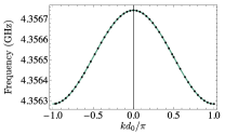
We calculate the phonon band structure for a beam with a unit cell as depicted in Fig. B.4(a) using the finite-element (FEM) simulation package COMSOL. This band structure is used in calculation of current in the main text (see Fig. B.4(b)). Repeating this nominal cell and deforming it in a periodic way (see Figure 3 in the main text) leads to the creation of a band of phonons that is composed of a coherent superposition of localized phononic states. As such, they strongly couple to a co-localized electromagnetic field. The localization of these modes means that they are well described by the tight-binding Hamiltonian (27). We take a particular deformation of the unit-cell (as shown in Figure 3 in the main text), and look at the bands close to the localized modes to verify our tight-binding approximations. In Fig. B.5 we see a very good agreement between the simulation and our theoretical model.
Appendix C Contrast calculation and room temperature results
As discussed in the main text we use a hybrid method to evaluate the contrast . The calculations are done with the band-structure of the superlattice for frequencies below 25 GHz. In frequency range of 25 GHz to 3 THz a linear dispersion () is assumed mingo2009nanoparticle , and only at room temperature, where frequencies above 3 THz play an important role, mean free paths and band-structure from first-principle calculations are used and taken from Ref. esfarjani2011heat . We employ the Landauer formalism to calculate the current jeong2012thermal . The total current is given by considering these contributions together with the current through the non-reciprocal tight-binding band
| (52) | ||||
where density of modes is calculated from the superlattice band structure. The density of modes in the bulk material, , is obtained from the linear dispersion (up to 3 THz) and first-principles calculations(above 3 THz). The last line of equation (52) takes the effect of non-reciprocal band into account. The transmission probability of this band is the product of the probabilities shown in Fig. A.3 and the factor that is calculated using the scattering rates discussed in the main text. The ratio of the non-reciprocal part to the total current reported in the main text is given by
| (53) |
The validity of the hybrid method rests on the separation of length scales of the problem. As seen in Table 1, the length scale of each frequency interval is comparable to either the size of the unit-cell of the superlattice, or the size of the unit cell of the crystal, which corresponds to the dispersion that is used.
| Frequency | Dispersion | Wavelength (unit-cell) |
|---|---|---|
| 0-25 GHz | Superlattice band structure | 200 nm (456 nm) |
| 25 GHz - 3 THz | Linear dispersion (Debye) | 200 nm - 2 nm |
| 3 THz - 15 THz | First-principles | 2 nm - 0.4 nm (0.5 nm) |
In the main text we used the hybrid method to calculate the thermal current at 4 K and 0.4 K. Here, we use the same method to show the effect of impurities on the thermal conductivity of silicon at room temperature (see Fig. C.6(a)) and calculate the contrast in Si90Ge10 optomechanical crystal with 10 nm nano-particles (see Fig. C.6(b)). The thermal conductivity is calculated using the Debye formula following Ref. mingo2009nanoparticle
| (54) |
where the cutoff is taken to be 3 THz, and ’s are the sound velocities of longitudinal and transverse branches. We use first-principle calculations esfarjani2011heat modified with Matthiessen rule for higher frequencies. In Fig. C.6(a) we show the contrast that is calculated using the described method.
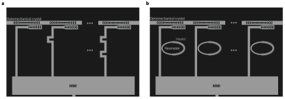
Appendix D On-chip implementation of the phase gradient
An on-chip approach to implementing a position dependent phase in the laser drive, i.e. , is using the propagation phase of light () in a waveguide. We propose using a power divider such as a multi-mode interference (MMI) beam splitter to distribute the power equally hosseini20111 to all cavities. Then, for a chosen value of , the phase gradient can be implemented by two methods: (1) varying the length of the connection or (2) by using zero-loss resonators as all-pass filters. In the first method, the length of each waveguide is varied, for example by meandering the path, so that the phase is tuned at the connection (see Fig. D.7)(a)). In the second case, each waveguide is coupled to a zero-loss resonator. The resonators acts as all-pass filters and transmit the light perfectly. However, the transmitted light picks up a phase that is related to the resonance frequency of the resonator. This frequency, and consequently the phase, can be tuned by temperature. Therefore, by using a heater, the phase of the drive at each site can be tuned Sunil14 . Finally, each connection is evanescently coupled to the optomechanical crystal at its corresponding position OscarEvan13 .