Making Faces: Universal Inverse Design of Surfaces with Thin Nematic Elastomer Sheets
Abstract
Programmable shape-shifting materials can take different physical forms to achieve multifunctionality in a dynamic and controllable manner. Although morphing a shape from 2D to 3D via programmed inhomogeneous local deformations has been demonstrated in various ways, the inverse problem – programming a sheet to take an arbitrary desired 3D shape – is much harder yet critical to realize specific functions. Here, we address this inverse problem in thin liquid crystal elastomer (LCE) sheets, where the shape is preprogrammed by precise and local control of the molecular orientation of the liquid crystal monomers. We show how blueprints for arbitrary surface geometries as well as local extrinsic curvatures can be generated using approximate numerical methods. Backed by faithfully alignable and rapidly lockable LCE chemistry, we precisely embed our designs in LCE sheets using advanced top-down microfabrication techniques. We thus successfully produce flat sheets that, upon thermal activation, take an arbitrary desired shape, such as a face. The general design principles presented here for creating an arbitrary 3D shape will allow for exploration of unmet needs in flexible electronics, metamaterials, aerospace and medical devices, and more.
Department of Physics and Astronomy, University of Pennsylvania, Philadelphia, PA 19104, USA
Department of Materials Science and Engineering, University of Pennsylvania, Philadelphia, PA 19104, USA
†These authors contributed equally to this work.
⋆E-mail: shuyang@seas.upenn.edu.
A common modality of biological systems is the ability to shape themselves into various morphologies in order to interact with their surrounding environment, a concept also widely adopted by mankind in various technological contexts[1]. Much effort has been invested in the last decades in the research of soft systems, that deform smoothly and continuously, often inspired by natural systems. Examples of such studies include, to name just a few, environmentally responsive hydrogels [2, 3], self-folding origami [4, 5] and kirigami [6], or smart textiles [7], with applications in soft robotics [8, 9], biomedicine [10, 11, 12], functional and artistic design [13]. In natural systems, the local structure often appears to be highly optimized for obtaining a certain shape that is necessary for fulfilling a certain function. Such high-end design is hard to achieve artificially, and biomimetics is often used to reproduce designs that appear in the natural world [14, 15]. Still the question remains, how does one create a new stimulus-responsive design from scratch? How does the local structure at every point need be set in order to get the desired global shape and response?
The answer depends on the local properties of the materials in use. For example, thin hydrogel sheets with programmable local isotropic expansion are widely studied in the context of shaping [2, 3]. In these systems, the inverse design problem is mathematically well understood and generally solved [16]. However, properties such as low elastic modulus, small deformations, slow response times, or the need for very specific aqueous environmental conditions may render such systems unsuitable for many applications. A class of materials that exhibit properties that are well suited for a wide range of design applications is liquid crystal elastomers (LCEs), that are lightly crosslinked polymer networks of liquid crystals (LCs). The inherent molecular anisotropy of LCs allows engineering the mechanical response of LCEs with fine control over both the magnitude and direction of the local strain. Compared to osmosis-driven hydrogel-based responsive materials, LCEs are characterized with high mechanical strength and quick response () [17], while exhibiting large anisotropic local deformations () in response to a variety of external stimuli, e.g. heat, light, or magnetic field. These materials have therefore been in the focus of much research in recent years, both theoretical and experimental [18]. Since the anisotropic local deformation is different from the isotropic one, describing the local geometry of LCEs requires an entirely different mathematical framework than that used to describe isotropic materials systems such as hydrogels. Namely, it requires linking the geometry to the local molecular orientation – the nematic director – which is a principal axis of the local anisotropic deformation. Several recent theoretical works establish the relation between the nematic director field in an undeformed LCE sheet and the geometry it adopts upon stimulation, either in a discrete framework [19, 20] or in a continuous one [21, 22].
The inverse design problem for LCE-type deformations, i.e. finding a planar director field that would induce an arbitrary 2-dimensional (2D) geometry, was discussed in [21] and later in [15] but was not solved for the general case. General solutions were found for similar, less constrained inverse problems, namely when relaxing the planar-field demand and assuming full control over the 3-dimensional (3D) director field at every point [23], or when relaxing the fixed magnitude demand and assuming full control over the entire planar deformation tensor [24]. Nonetheless, experimental realization of those assumptions will be extremely challenging. This is in contrast to planar-director LCEs, for which many experimental methods have been investigated, aiming to improve the accuracy and spatial resolution of the nematic director field at every point. Initial attempts to construct both smooth curvature fields and discrete ones proved successful [25, 22, 26, 27], thus laying the cornerstone for realizing arbitrary designs of thin LCE sheets. Nevertheless, there remain several obstacles before reaching this goal; first, the general inverse design problem for planar fields is still unresolved; second, assuming a solution exists, one needs to be able to accurately and faithfully imprint it onto a thin LCE sheet and obtain the correct local stimulus-responsive deformation in practice; third, obtaining the right 2D geometry is not enough since it can have many different isometric embeddings in space, and since the system might end up being dynamically stuck in a non-isometry or in an otherwise undesired configuration. Therefore, control over additional degrees of freedom needs be achieved in order for these methods to be applied for general designs.
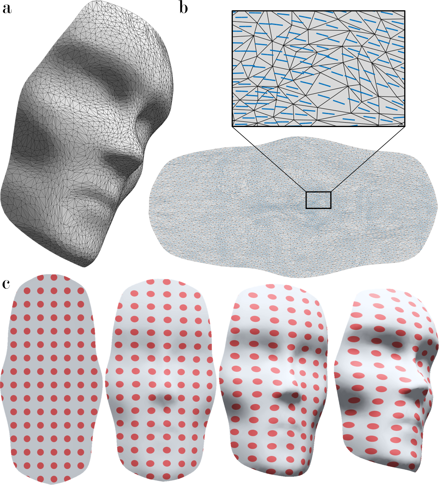
In this work we resolve some of these issues in a first attempt to allow the design of arbitrarily shaped surfaces from flat LCE sheets, implementing several novel theoretical and experimental techniques. We first take a numerical approach in approximating a solution to the inverse design problem, thus obtaining a planar nematic director field that equips the sheet with the desired 2D metric tensor. We realize these designs using a variation on the top-down microfabrication technique that was previously developed by some of the authors [27] to precisely control the molecular orientation at every point in the LCE sheet. Combined with new LCE polymer chemistry based on a “click” reaction that can efficiently and faithfully produce uniform strain across the film, we create a high-accuracy realization of the theoretical designs with precise control over both the direction and magnitude of the local strain in the polymer films. Furthermore, we incorporate higher-order techniques, namely the introduction of local target directional curvatures throughout the sheet and specifically around its edge, in order to better insure buckling of the sheet towards the correct isometry and avoid stagnation at local equilibria away from the desired design. We show how the combination of these methods allows us to create sheets that upon activation take an arbitrary design, e.g. a face (Fig. 1).
The mathematical formulation of the inverse design problem for thin planar nematic elastomer plates was presented in [21]. It involves, given a desired 2D metric tensor , finding coordinates and a director field , so that takes the form
| (1) |
Here, and are the local expansion ratios parallel and perpendicular to the nematic director field respectively, and is the planar rotation matrix by angle .
We take a numerical approach for finding an approximate solution to eq. (1). We start with a desired surface given as a triangulated mesh in 3D, whose vertices are initially parameterized by some 2D coordinates, and with certain values of and that describe the local material deformation at a certain desired temperature (Fig. 2c). Following the approach of [21], we iteratively modify this coordinate parameterization to bring the transformed metric tensor’s eigenvalues close to at every mesh triangle. Our algorithm for this procedure, based on a numerical algorithm presented in [28], is described in detail in Supplementary materials. Its output is a 2D coordinate mesh, , with the same triangulation as our input surface, along with a director angle defined at each mesh triangle. The 2D intrinsic geometry of such a sheet is expected to follow Eq (1), hence it is Euclidean at preparation temperature () and approximates the geometry of our desired surface upon accepting the target values of and . We evaluate the approximation error, and refine the mesh or run the algorithm starting at a different initial condition if necessary.
To realize the designs given by our numerical algorithm, it is crucial to prepare spatially heterogeneous LCEs with precisely controlled lateral deformation at every point. It thus requires control not only of the arbitrary position-dependent orientation of the nematic director, but also of the magnitude of local principal strains throughout the film. Since the theory and numerical algorithm assume constant principal strains across the film, it is necessary to fulfill this requirement in the real experimental system. However, traditional LCE chemistry[29] that is based on free radical polymerization seriously suffers from the inhibition reaction of oxygen from the ambient air, and the uniformity of crosslinking density in the resultant LCE film cannot be guaranteed, which in turn would affect the local strain in the film. To overcome this challenge, we develop a novel surface alignable LCE chemistry based on an oxygen mediated thiol-acrylate “click” reaction (Fig. 2b), allowing for immediate locking of the LC director field in the local domains. In thiol–acrylate reactions, it has been reported[30, 31] that oxygen serves as a chain transfer agent that promotes the condensation reaction of thiol-acrylate, and the polymerization rate is not affected significantly by the presence of oxygen (see reaction mechanism in Fig. S1). Seeking to enable high and uniform strain in LCE, we take advantage of this oxygen-friendly “click” reaction, and use bifunctional dithiol and diacrylate as precursors to produce main-chain LCEs (Fig. 2b).
Unfortunately, mixing high fraction of non-mesogenic reactant into mesogenic liquid crystal could create a new problem in maintaining the LC phase [32], as a result of the drastic influence of the non-mesogenic chains on the LC packing symmetry. To suppress this effect, we prepare LCEs via a two-step synthetic procedure. First, we pre-polymerize mesogenic diacrylates (RM82) and non-mesogenic dithiol (1,3-propane dithiol) via a base-catalyzed “click” reaction to generate a new mesogenic dithiol oligomer (Fig. S2). After reaction, the dithiol oligomer is in a nematic phase at room temperature and can be homogenously mixed with RM82 at any fraction ratio without destroying the nematic phase. The mixture has an extremely large nematic window of (Fig. S3a). Finally, we obtain the LCEs through photopolymerization of the RM82/dithiol oligomer mixture via ”click” chemistry (Fig. S1a), which is found extremely efficient, leading to gelation after 20 seconds of UV exposure at (Fig. S4a).
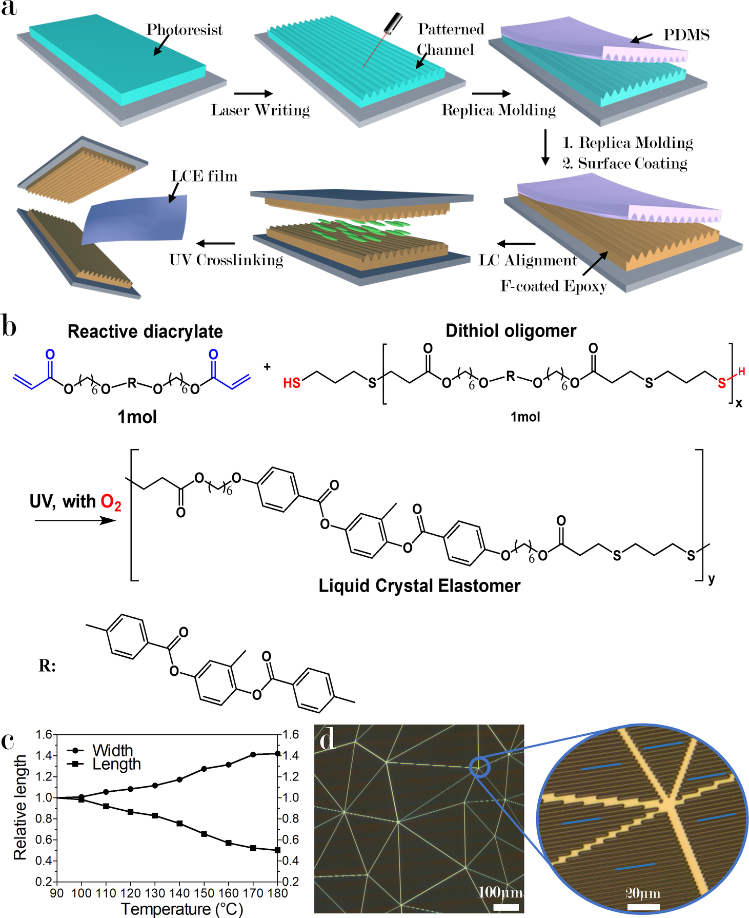
After crosslinking, we end up with a low modulus and low glass transition temperature elastomer (Fig. S3b,S4b). The LCE film shows clear birefringence and shape changes in response to heating (Fig. S5a). We prepare a uniformly aligned LCE film to measure the variation in the length and width of the film upon heating, and calculate the thermo-responsive strain plotted in Fig. 2c and Fig. S5b. The maximum strain of our LCE system is found to be in the system of RM82/dithiol oligomer at ratio of functional group. These large values of grant access to a wide variety of 2D geometries via our numerical algorithm.
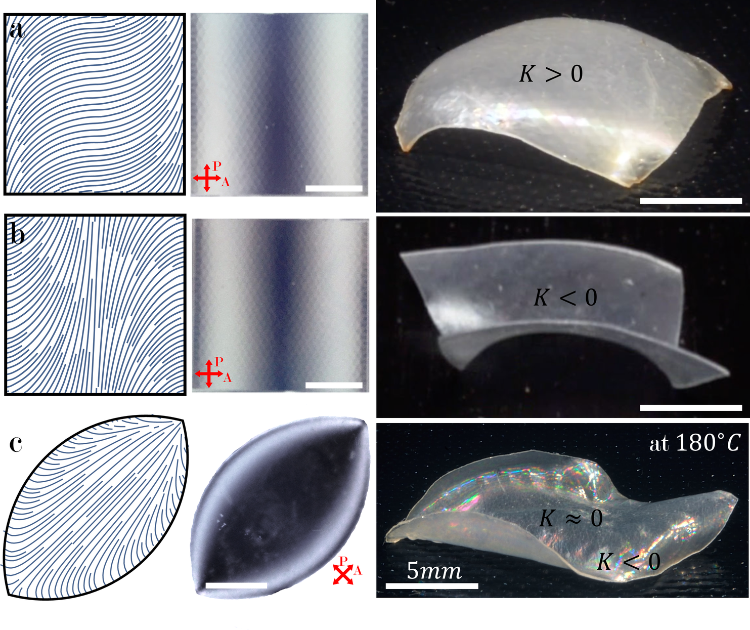
Spatial control over the nematic director field has been demonstrated in photo-alignment systems[26] and in our previously reported photo-patterned 1D channel system [27] (with feature size ). Here, we implement our method to align LCs according to our numerical designs. To further improve the alignment quality, we employ a new photo-patterning technique through direct laser writing (DLW, see details in Supplementary materials) to prepare even smaller pattern feature size of that gives a much higher surface anchoring energy [33] (detailed discussion in Supplementary materials). We prepare channel patterned molds with channel width of , spacing of , and depth of , arranged into monolithic domains of average size (Fig. 2d, S6), which correspond with the discrete elements in our numerical algorithm. The two sides of the a mold are placed with a spacing between them, into which we insert the RM82/dithiol oligomer melt. The nematic director locally aligns with channel direction, and fast UV crosslinking traps it inside the solid LCE films (Fig. 2a, S4a). We use this system to realize designs obtained by our numerical algorithm, with good success in reproducing several simple designs. Some of these are shown in Fig. 3 – surfaces of constant positive and negative Gaussian curvatures (which can be thought of as building blocks for arbitrary 2D geometries), and the shape of a leaf with negative Gaussian curvature exponentially decaying away from the edge [34].
Nonetheless, we face more challenges when trying to produce more complex models, e.g. the face in Fig. 1, whose 2D geometry consists of smaller length scales and alternating curvatures. One reason for this might be that with such geometries the thin limit assumption is less valid and bending energy plays a bigger role trying to locally flatten the sheet. Considering the size of our monolithic domains as a lower bound on the radii of curvature in our designs, we alleviate this problem by decreasing the film thickness to to approach the thin limit, however with the mechanical integrity of the LCE film in mind, we refrain from going lower. Another problem with complex designs is the abundance of different isometries and near-isometries of the desired shape, which is further aggravated by the dynamic process in which different regions in our sample might initially buckle in different directions and be left stuck away from the system’s global ground state.
To grapple with these issues we augment our designs with a small gradient in the nematic director across the sheet’s thickness, introducing non-trivial local reference curvatures. As is explained in [21], this method cannot be used to create any desired local curvature; with strictly planar anchoring, it can only induce a reference curvature tensor with equal and opposite principal curvatures, with principal curvature directions at with respect to the thickness-averaged director. The only additional scalar-field degree of freedom is the absolute value of these principal curvatures, which is proportional to the magnitude of the local director field gradient at every point [21]. We calculate the value of this scalar field that minimizes the discrepancy between the induced reference curvature and the curvature of the desired field. A detailed calculation can be found in the Supplementary materials. The output of the numerical calculation are values of evaluated at each mesh triangle. This gives us for each mesh triangle two director fields: for the top surface of the sheet and for the bottom surface. Since the difference between these two fields is small (in our models ) and continuous, the nematic strain caused by it is not enough to compromise surface anchoring or to promote nematic defects, nor does it significantly change the induced reference metric (see discussion in Supplementary materials).
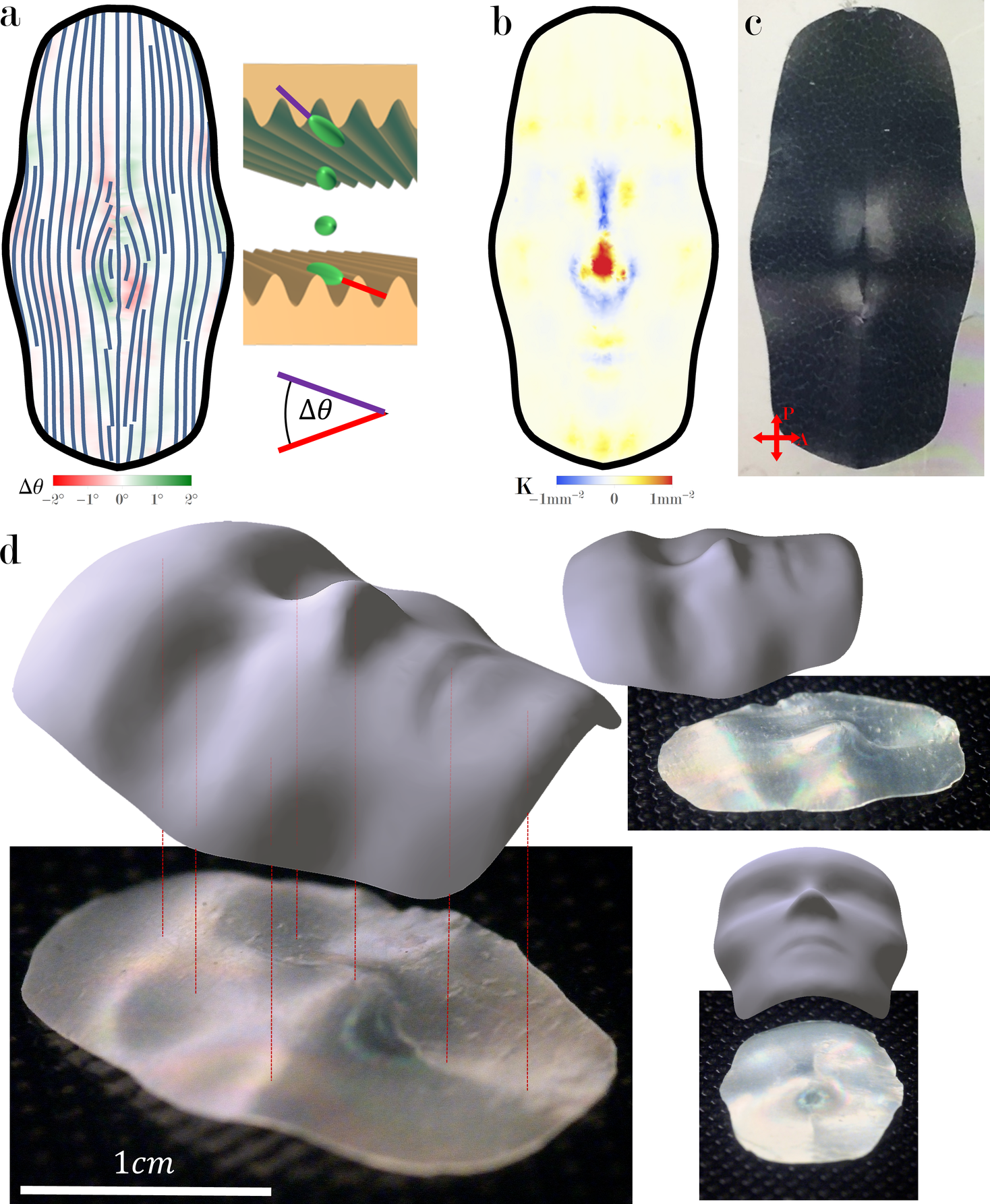
We realize such a director field by creating two independent channel patterns for the top and bottom parts of the mold, instead of using two mirror images of the same pattern. We still use the same triangulated mesh for both sides, only the channels within each monolithic domain are oriented in slightly different directions (Fig. 4a). The resulting director field remains essentially planar throughout the sample, and twists smoothly from top to bottom to match the direction of the channels on both sides. When heated, the reference curvatures cause the resulting LCE film to buckle in the desired direction at certain areas, thus pushing it dynamically toward the preferred isometry – a face (Fig. 4d and Fig. S7).
This work brings together novel numerical and experimental methods to address a universal inverse problem, that is, how to reconstruct 3D surfaces from 2D sheets of anisotropic LCEs. We established an explicit protocol for preprogramming any desired shape into an LCE sheet. Our protocol is not limited in material or scale; liquid crystals are not necessarily molecular, they can be any material with long range orientational order, and an “LCE-like” anisotropic material could be any liquid crystal coupled with any elastic medium. Our designs can therefore be broadly used, in systems ranging from cellulose nanocrystals embedded in polymer networks to sewing threads embedded in hydrogels. This allows the design of shape-shifting surfaces at a wide variety of length scales and material properties, which, combined with the shape-universality of our design scheme, opens the door for countless technological applications.
References
References
- [1] Burgert, I. & Fratzl, P. Actuation systems in plants as prototypes for bioinspired devices. Philos. Trans. R. Soc. A Math. Phys. Eng. Sci. 367, 1541–1557 (2009).
- [2] Klein, Y., Efrati, E. & Sharon, E. Shaping of Elastic Sheets by Prescription of Non-Euclidean Metrics. Science 315, 1116–1120 (2007).
- [3] Kim, J., Hanna, J. A., Byun, M., Santangelo, C. D. & Hayward, R. C. Designing responsive buckled surfaces by halftone gel lithography. Science 335, 1201–5 (2012).
- [4] Tolley, M. T. et al. Self-folding origami: shape memory composites activated by uniform heating. Smart Mater. Struct. 23, 094006 (2014).
- [5] Na, J. H. et al. Programming reversibly self-folding origami with micropatterned photo-crosslinkable polymer trilayers. Adv. Mater. 27, 79–85 (2015).
- [6] Zhang, Y. et al. A mechanically driven form of Kirigami as a route to 3D mesostructures in micro/nanomembranes. Proc. Natl. Acad. Sci. 112, 11757–11764 (2015).
- [7] Hu, J., Meng, H., Li, G. & Ibekwe, S. I. A review of stimuli-responsive polymers for smart textile applications. Smart Mater. Struct. 21, 053001 (2012).
- [8] Shepherd, R. F. et al. Multigait soft robot. Proc. Natl. Acad. Sci. U. S. A. 108, 20400–3 (2011).
- [9] Trivedi, D., Rahn, C. D., Kier, W. M. & Walker, I. D. Soft robotics: Biological inspiration, state of the art, and future research. Appl. Bionics Biomech. 5, 99–117 (2008).
- [10] Woltman, S. J., Jay, G. D. & Crawford, G. P. Liquid-crystal materials find a new order in biomedical applications. Nat. Mater. 6, 929–938 (2007).
- [11] Fernandes, R. & Gracias, D. H. Self-folding polymeric containers for encapsulation and delivery of drugs. Adv. Drug Deliv. Rev. 64, 1579–1589 (2012).
- [12] Randall, C. L., Gultepe, E. & Gracias, D. H. Self-folding devices and materials for biomedical applications. Trends Biotechnol. 30, 138–146 (2012).
- [13] Ritter, A. Smart materials in architecture, interior architecture and design (Birkhäuser, 2007).
- [14] Ionov, L. Biomimetic Hydrogel-Based Actuating Systems. Adv. Funct. Mater. 23, 4555–4570 (2013).
- [15] Gladman, A. S., Matsumoto, E. A., Nuzzo, R. G., Mahadevan, L. & Lewis, J. A. Biomimetic 4D printing. Nat. Mater. 15, 413–418 (2016).
- [16] Chern, S.-S. An Elementary Proof of the Existence of Isothermal Parameters on a Surface. Proc. Am. Math. Soc. 6, 771–782 (1955).
- [17] Camacho-Lopez, M., Finkelmann, H., Palffy-Muhoray, P. & Shelley, M. Fast liquid-crystal elastomer swims into the dark. Nat. Mater. 3, 307–10 (2004).
- [18] Warner, M. & Terentjev, E. M. Liquid Crystal Elastomers. March (OUP Oxford, 2003).
- [19] Modes, C. D., Bhattacharya, K. & Warner, M. Disclination-mediated thermo-optical response in nematic glass sheets. Phys. Rev. E 81, 060701 (2010).
- [20] Modes, C. D. & Warner, M. Blueprinting nematic glass: Systematically constructing and combining active points of curvature for emergent morphology. Phys. Rev. E 84, 021711 (2011).
- [21] Aharoni, H., Sharon, E. & Kupferman, R. Geometry of Thin Nematic Elastomer Sheets. Phys. Rev. Lett. 113, 257801 (2014).
- [22] Mostajeran, C., Warner, M., Ware, T. H. & White, T. J. Encoding Gaussian curvature in glassy and elastomeric liquid crystal solids. Proc. R. Soc. London A Math. Phys. Eng. Sci. 472, 20160112 (2016).
- [23] Plucinsky, P., Lemm, M. & Bhattacharya, K. Programming complex shapes in thin nematic elastomer and glass sheets. Phys. Rev. E 94, 010701 (2016).
- [24] van Rees, W. M., Vouga, E. & Mahadevan, L. Growth patterns for shape-shifting elastic bilayers. Proc. Natl. Acad. Sci. U. S. A. 114, 11597–11602 (2017).
- [25] de Haan, L. T., Sánchez-Somolinos, C., Bastiaansen, C. M. W., Schenning, A. P. H. J. & Broer, D. J. Engineering of complex order and the macroscopic deformation of liquid crystal polymer networks. Angew. Chem. Int. Ed. Engl. 51, 12469–72 (2012).
- [26] Ware, T. H., McConney, M. E., Wie, J. J., Tondiglia, V. P. & White, T. J. Voxelated liquid crystal elastomers. Science 347, 982–984 (2015).
- [27] Xia, Y., Cedillo-Servin, G., Kamien, R. D. & Yang, S. Guided Folding of Nematic Liquid Crystal Elastomer Sheets into 3D via Patterned 1D Microchannels. Adv. Mater. 28, 9637–9643 (2016).
- [28] Liu, L., Zhang, L., Xu, Y., Gotsman, C. & Gortler, S. J. A local/global approach to mesh parameterization. Eurographics Symp. Geom. Process. 27, 1495–1504 (2008).
- [29] Broer, D. J., Crawford, G. P. & Žumer, S. Cross-linked liquid crystalline systems : from rigid polymer networks to elastomers (CRC Press, 2011).
- [30] Cramer, N. B. & Bowman, C. N. Kinetics of thiol-ene and thiol-acrylate photopolymerizations with real-time fourier transform infrared. J. Polym. Sci. Part A Polym. Chem. 39, 3311–3319 (2001).
- [31] O’Brien, A. K., Cramer, N. B. & Bowman, C. N. Oxygen inhibition in thiol–acrylate photopolymerizations. J. Polym. Sci. Part A Polym. Chem. 44, 2007–2014 (2006).
- [32] Ware, T. H., Perry, Z. P., Middleton, C. M., Iacono, S. T. & White, T. J. Programmable Liquid Crystal Elastomers Prepared by Thiol–Ene Photopolymerization. ACS Macro Lett. 4, 942–946 (2015).
- [33] Berreman, D. W. Solid surface shape and the alignment of an adjacent nematic liquid crystal. Phys. Rev. Lett. 28, 1683–1686 (1972).
- [34] Sharon, E., Roman, B. & Swinney, H. L. Geometrically driven wrinkling observed in free plastic sheets and leaves. Phys. Rev. E 75, 46211–46217 (2007).
We acknowledge support by the National Science Foundation (NSF) DMR/Polymer program, DMR-1410253 (S.Y.). This work is also partially supported by NSF/EFRI-ODISSEI EFRI 13-31583, NSF DMR-1262047, and a Simons Investigator grant from the Simons Foundation (R.D.K.).
Supplementary information is available in the online version of the paper.
See pages - of SM.pdf