Proceedings of the Fifth Annual LHCP
SciFi: A large Scintillating Fibre Tracker for LHCb
Plamen Hopchev
Laboratory for High-Energy Physics
EPFL, Lausanne, Switzerland
On behalf of the LHCb SciFi Tracker group
ABSTRACT
The LHCb detector will be upgraded during the Long Shutdown 2 (LS2) of the LHC in order to cope with higher instantaneous luminosities and to read out the data at 40 MHz using a trigger-less readout system. The current LHCb main tracking system will be replaced by a single homogeneous detector based on scintillating fibres. This contribution gives an overview of the scintillating fibre tracker concept and presents the experience from the series production complemented by most recent test-beam and laboratory results.
PRESENTED AT
The Fifth Annual Conference
on Large Hadron Collider Physics
Shanghai Jiao Tong University, Shanghai, China
May 15-20, 2017
1 Introduction
The LHCb upgrade in Long Shutdown 2 of the LHC (2019–2020) will improve significantly the experiment sensitivity in the flavour physics sector and will extend the LHCb physics programme [1, 2]. Along with sub-detector replacement and enhancements, LHCb will employ a new fully software trigger with superior efficiency and flexibility. The instantaneous luminosity will be increased by a factor of five to , aiming to collect 50 fb–1 over 10 years.
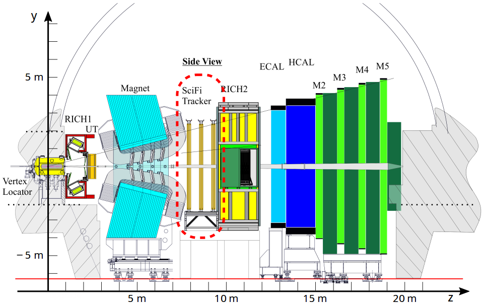
The current LHCb main tracking system, composed of an inner and outer tracking detector, will not be able to cope with the increased particle multiplicities and will be replaced by a single homogeneous detector based on scintillating fibres (see Fig. 1). The new Scintillating Fibre (SciFi) Tracker will cover a total detector area of 340 m2 and will provide a spatial resolution for charged particles better than 100 in the bending direction of the LHCb spectrometer [3].
2 Scintillating Fibre Tracker
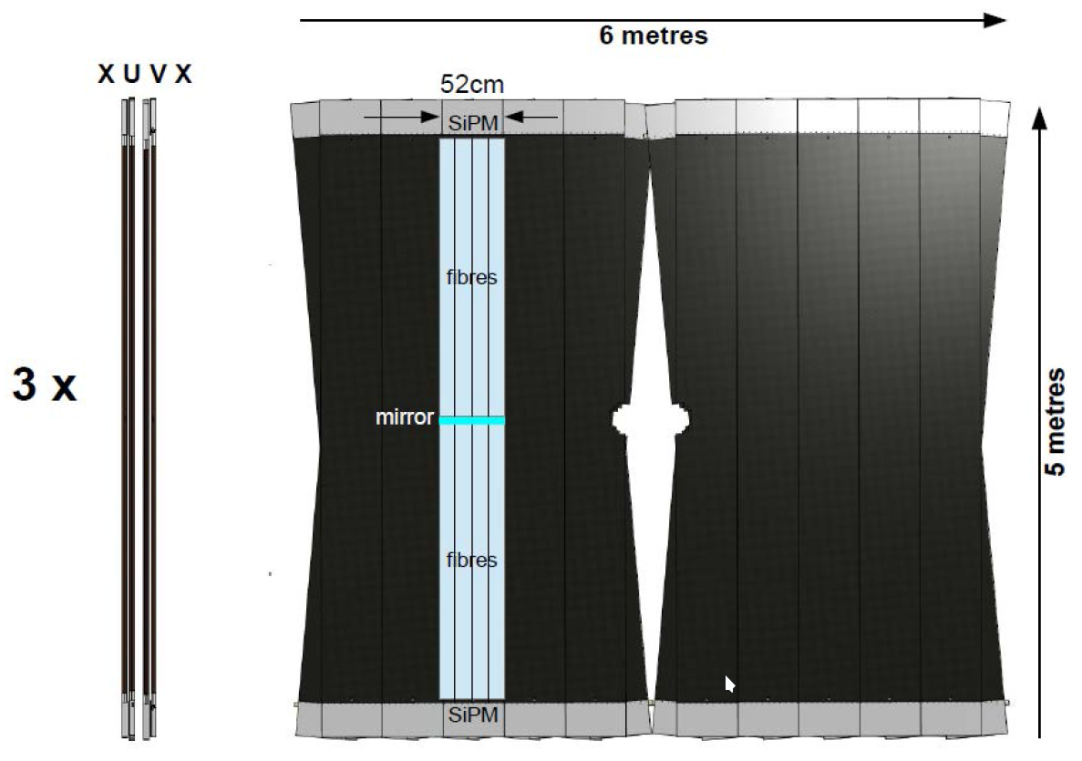
The SciFi tracker consists of three stations each with four detection planes, as shown in Fig. 2. The detector is built from individual modules (0.5 m 4.8 m), each comprising 8 fibre mats with a length of 2.4 m as active detector material. The fibre mats consist of 6 layers of densely packed blue-emitting scintillating fibres with a diameter of 250 . The scintillation light is recorded with arrays of state-of-the-art multi-channel silicon photomultipliers (SiPMs). A custom ASIC is used to digitize the SiPM signals. Subsequent digital electronics performs clustering and data-compression before the data is sent via optical links to the DAQ system. To reduce the thermal noise of the SiPM, in particular after being exposed to a neutron fluence of up to 1012 neq/cm2, expected for the lifetime of the detector, the SiPM arrays are mounted in so called cold-boxes and cooled down by 3D-printed titanium cold-bars to C.
The detector is designed to provide low material budget (1 % per layer), hit efficiency of 99 % and a resolution better than 100 . These performance figures must be maintained over the lifetime of the detector which will receive radiation dose up to 35 kGy near the beam pipe. The full detector, comprising 590 000 channels, is read out at 40 MHz.
The rest of this section provides information on the main detector components.
2.1 Scintillating Fibres
The fibre type is SCSF-78MJ, produced by Kuraray, Japan. It has a diameter of 0.25 mm and is made of polystyrene core with added dye and wavelength shifter, and two claddings with lower refraction index (see Fig. 3).
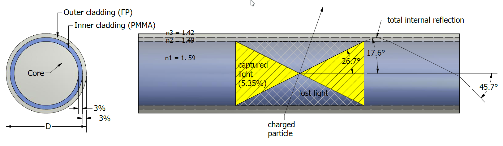
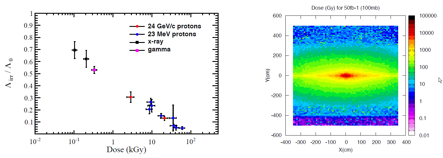
The fibre produces several thousand photons per 1 MeV deposited energy, with a capture fraction of about 5 % [3]. The decay time constant of the scintillation light signal is 2.8 ns, while the emission spectrum extends from about 400 to 600 nm and peaks at 450 nm near the source. The attenuation length is greater than 3 m, with small dependence on the wavelength. However, the ionizing radiation degrades the optical transparency of the fibre. Dedicated irradiation tests with different particle types and energies were performed in order to quantify this effect. It was estimated that at the end of the detector lifetime the signal amplitude from the innermost part of the detector will be reduced by up to 40 % (dose 35 kGy) [3], while the radiation effect becomes relatively marginal at distances of about 50 cm from the beam pipe (dose 1 kGy), see Fig. 4. The radiation effects were taken into account in the detector design. Replacement modules are prepared for the areas exposed to highest radiation.
2.2 Fibre mats and modules
The active elements of the detector are scintillating fibre mats composed of six fibre layers, with dimensions width length height: 130.65 2424.0 1.4 mm. A mat cross-section is shown in Fig. 5.
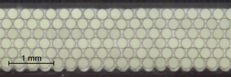
The mats are produced on a winding wheel with threaded surface with pitch of 275 . Epoxy glue is applied before each fibre layer and TiO2 powder is added to the glue to reduce the optical cross-talk between fibres. Reference alignment pins are produced on the mats from cavities on the winding wheel surface. These alignment pins are used later during the module assembly to ensure proper alignment of the mats. The scintillation light is detected only on one end of the mat, and a mirror is glue on the other end to maximize the signal amplitude.
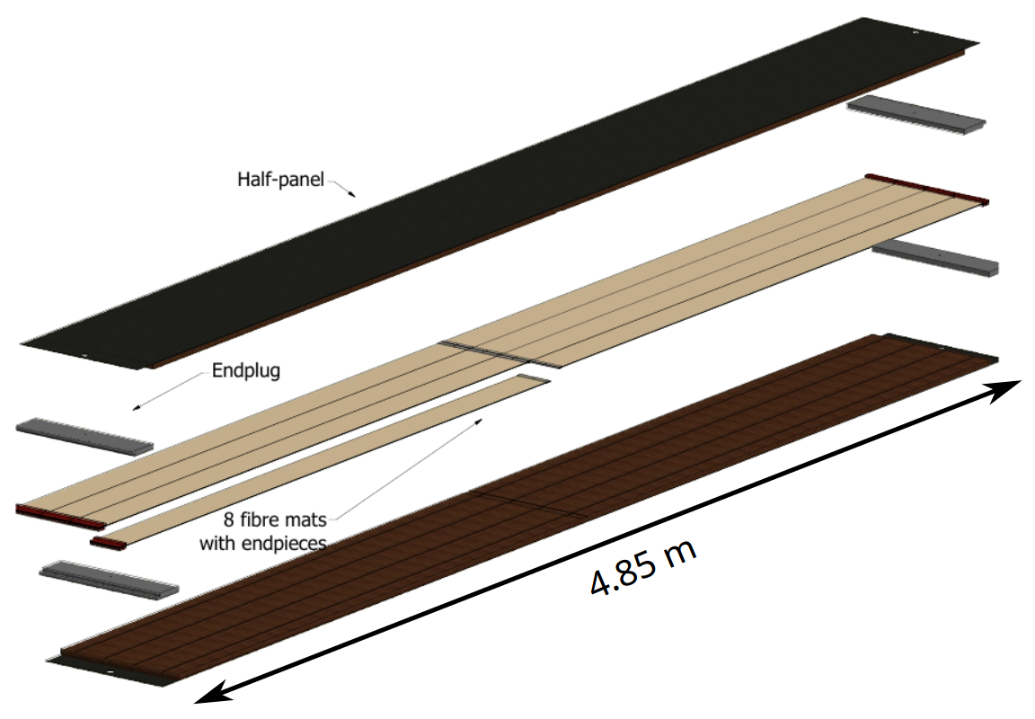
During the module assembly 8 fibre mats are aligned and glued together with honeycomb/carbon-fibre composite panels (see Fig. 6). Cooling enclosure, SiPMs and electronics are added later. Despite the large dimensions (approx. m) the construction method results into stable and stiff detector modules with material budget of only 1.1% per module.
2.3 Silicon Photomultipliers
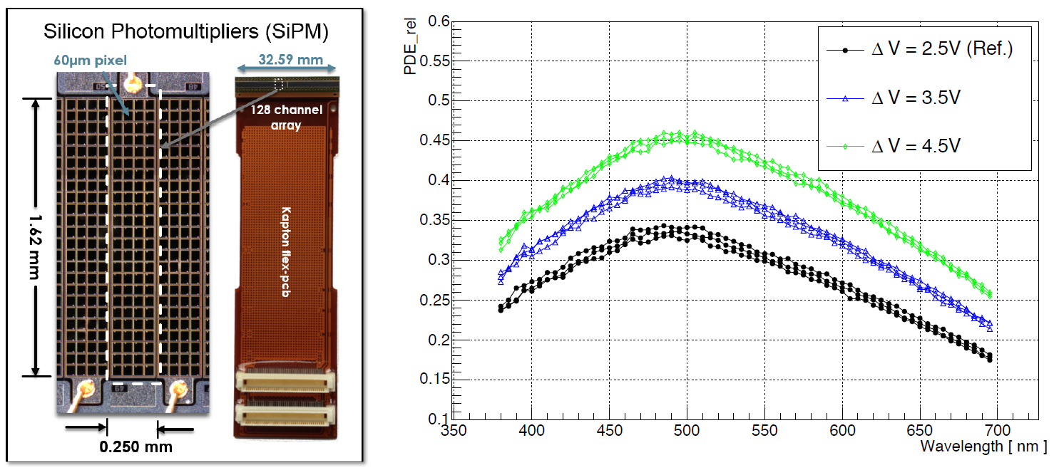
The fibres are read-out by 128-channel silicon photo-multiplier (SiPM) arrays from Hamamatsu, with individual channel size of 0.25 1.62 mm (see Fig. 7). Several development iterations were made to improve the SiPM characteristics. The SiPM version for the SciFi tracker provides photon detection efficiency about 45 % at the nominal overvoltage 3.5 V, and relatively low noise and cross-talk. To suppress dark noise after irradiation, the SiPMs will be cooled to C during operations. Irradiation tests showed that the SiPM dark count rate (DCR) increases linearly with the neutron fluence. After receiving neutron fluence of neq/cm2, which is about half of the expected fluence for the lifetime of the detector, the SiPMs produce DCR of 14 MHz per channel at C. Such DCR rates pose no problem for the detector operation, because the detector will be read out at 40 MHz, retaining only signal clusters of at least 4.5 photo-electrons.
2.4 Front-end Electronics
For efficient testing and maintenance, the front-end signal processing is performed on three separate electronics boards. Initially, the SiPM signal is read by PACIFIC – a custom 64-channel front-end ASIC developed for the SciFi tracker. The PACIFIC features a pre-amplifier, a fast shaper, and dual gated integrators providing almost zero dead-time. The analog signal is digitized by a triple-threshold tunable comparator. The digitized channel data are sent to a clusterization board where FPGAs combine the individual channels into clusters. Later on, a master board sends the data via optical links to the back-end DAQ system.
3 Testbeam performance
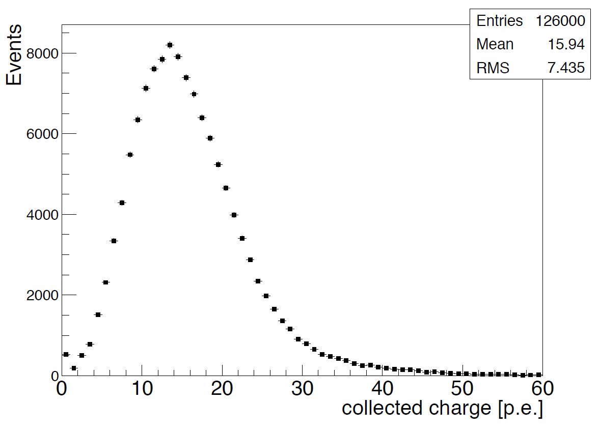
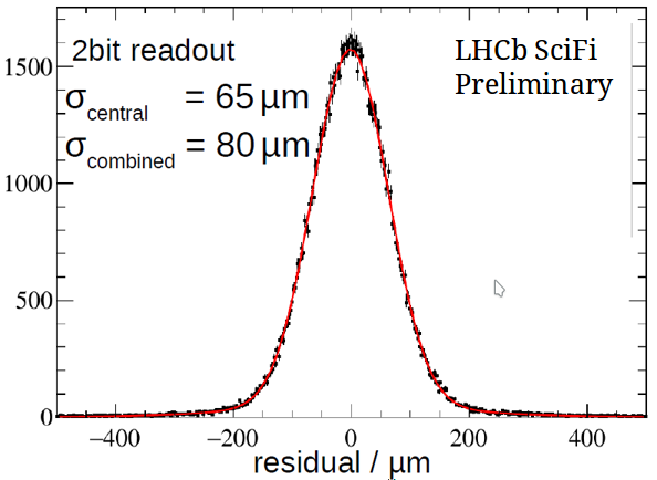
Several testbeam campaigns demonstrated good performance of the SciFi mats and electronics. The main detector characteristics were measured with proton/pion beams at CERN and electron beams at DESY, using the nominal SciFi readout components. Nominal light yield of 16 photo-electrons was achieved, as well as 99 % hit efficiency and 70 hit resolution (see Fig. 8). Fibre mats and SiPMs irradiated in different scenarios and dose were measured too, showing the expected behavior.
4 Conclusion
The LHCb Upgrade Scintillating Fibre tracker is a high-resolution detector covering area of 340 m2. It is based on scintillating fibres with diameter 0.25 mm, read-out with silicon photomultipliers. Nominal performance parameters have been achieved in laboratory and testbeam measurements. The 2.4-m long fibre mats provide light yield 16 photo-electrons, 99 % hit efficiency and position resolution of 70 . The serial production of the detector components is progressing well, and the detector installation is foreseen to start in 2019.
References
- [1] LHCb collaboration, “Letter of Intent for the LHCb Upgrade”, CERN-LHCC-2011-001, 03/2011
- [2] LHCb collaboration, “Framework TDR for the LHCb Upgrade”, CERN-LHCC-2012-007, 05/2012
- [3] LHCb collaboration, “LHCb Tracker Upgrade Technical Design Report”, CERN-LHCC-2014-001
- [4] C. Joram et al., “LHCb Scintillating Fibre Tracker Engineering Design Review Report: Fibres, Mats and Modules”, CERN-LHCb-PUB-2015-008, 03/2015