Induction Mapping of the 3D-Modulated Spin Texture of Skyrmions in Thin Helimagnets
Abstract
Envisaged applications of skyrmions in magnetic memory and logic devices crucially depend on the stability and mobility of these topologically non-trivial magnetic textures in thin films. We present for the first time quantitative maps of the magnetic induction that provide evidence for a 3D modulation of the skyrmionic spin texture. The projected in-plane magnetic induction maps as determined from in-line and off-axis electron holography carry the clear signature of Bloch skyrmions. However, the magnitude of this induction is much smaller than the values expected for homogeneous Bloch skyrmions that extend throughout the thickness of the film. This finding can only be understood, if the underlying spin textures are modulated along the out-of-plane direction. The projection of (the in-plane magnetic induction of) helices is further found to exhibit thickness-dependent lateral shifts, which show that this z modulation is accompanied by an (in-plane) modulation along the and directions.
I Introduction
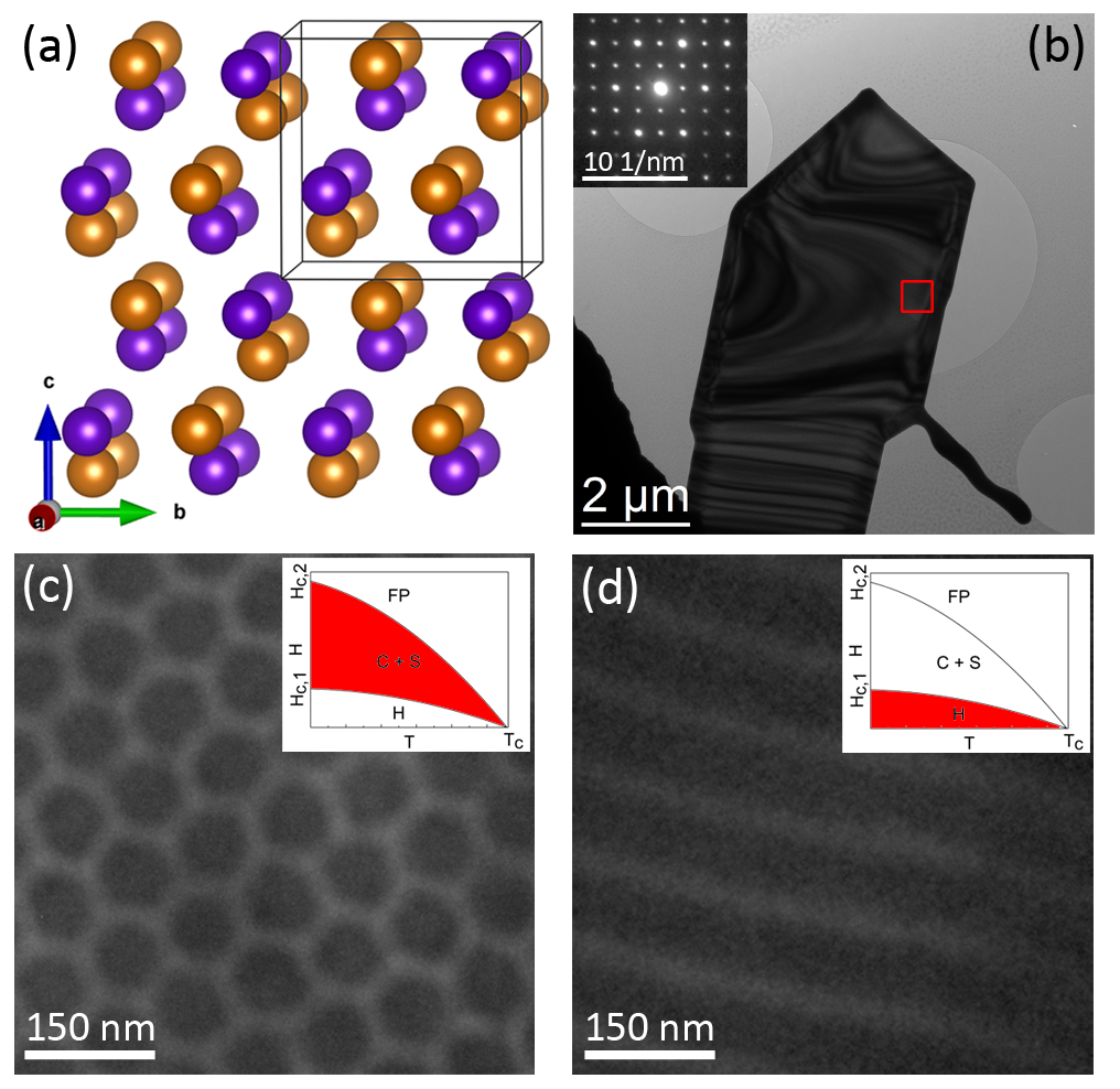
Skyrmions Bogdanov and Hubert (1994) are topologically non-trivial vortex-like spin textures, anticipated for application in spintronic technologies, referred to as skyrmionics, in next generation magnetic data processing and storage due to their facile manipulation by spin-polarized currents of very low magnitude Nagaosa and Tokura (2013); Kanazawa et al. (2017). The unique features of skyrmions, e.g., their dynamics, topological structure, competing magnetic interactions, are generally of great interest from a fundamental physics point, understanding emerging magnetic field-like interactions induced by topologically non-trivial chiral spin structures. In chiral-lattice ferromagnets without spatial inversion symmetry, such as the B20 compound (see Fig. 1 (a)) investigated in this work, skyrmions arise from the interplay between the Dzyaloshinskii-Moriya interaction Dzyaloshinsky (1958); Moriya (1960) and ferromagnetic exchange mechanisms Heisenberg (1926). Indeed, these and similar competing interactions, such as surface dipolar interaction, may lead to a whole zoo of non-trivial spin textures, including helical, cycloidal and various skyrmionic phases (antiskyrmions Nayak et al. (2017), N el skyrmions Kézsmárki et al. (2015)). Besides spin-polarized STM Heinze et al. (2011) and MFM Milde et al. (2013) probing the surface spin texture, X-ray microscopy Woo et al. (2016) was used to investigate the projected magnetic structure of skyrmions. Furthermore Lorentz transmission electron microscopy (TEM) and transport of intensity (TIE) holography have been employed to reveal the projected skyrmionic texture in a variety of studies Yu et al. (2010, 2011); Seki et al. (2012); Yu et al. (2013) in dependency of the applied magnetic field, temperature, sample thickness and crystallographic orientation, covering a large class of materials.
However, in particular for skyrmionics, knowledge about the full three-dimensional spin texture including its coupling to surfaces and interfaces, ubiquitous in thin film technology, is of fundamental importance, because it determines the stability and dynamics of the skyrmion state. Several theoretic studies predicted the occurence of 3D modulated skyrmion textures Rybakov et al. (2013); Leonov et al. (2016, 2014); Rybakov et al. (2016) as a consequence of surface anisotropies as well as 3D Dzyaloshinskii-Moriya interaction, also taking into account similarities to smectic liquid crystals Hinshaw et al. (1988); Glogarová et al. (1997). In particular, Rybakov, Borisov and Bogdanov theoretically predicted the presence of a chiral surface twist Rybakov et al. (2013), which was later experimentally discovered in epilayers of chiral magnets Wilson et al. (2013); Meynell et al. (2014). This surface modulation renders the skyrmionic state stable in thin film geometries (making it a ground state) as opposed to its metastable (i.e., excited) nature in the bulk. Later, a full-blown phase diagram of helical, skyrmionic, and other magnetic textures, such as Bobbers Zheng et al. (2017) has been computed for thin films of isotropic chiral magnets Rybakov et al. (2016). Experimental studies on modulated 3D spin textures in skyrmions have been, however, elusive to date. Similarly, almost none of the abundant microscopy studies Yu et al. (2010, 2011); Seki et al. (2012); Yu et al. (2013); Park et al. (2014); Kovács et al. (2016); Shibata et al. (2017); Jin et al. (2017) give quantitative values of projected magnetic fields carrying a fingerprint of the modulated 3D texture to the best knowledge of the authors.
Here, we seek to fill this gap by carrying out electron holography (EH) studies at different orientations of the sample to quantitatively reconstruct the projected magnetic field pertaining to both the helical and the skyrmion lattice phase in single crystal nanoplates of the isotropic chiral magnet . We compare our experimental results to magnetostatic simulations taking into account 3D modulation models such the chiral surface twist in order to discuss the presence of 3D spin textures in skyrmions. Our findings clearly suggest (i) the presence of inhomogeneous spin textures similar to previously discussed surface modulations and (ii) show that currently available spin structure models cannot account for our experimental results.
II Fundamentals
Following Bogdanov and Yablonskii (1989) one may describe the isotropic chiral magnet FeGe (space group ) with a continuum spin model (normalized magnetization vector ), i.e., as a (meta)stable state of the free energy
the interplay of ferromagnetic exchange and the Dzyaloshinskii-Moriya interaction leads to the formation of a helical spin order with a periodicity determined by the ratio of the Dzyaloshinskii–Moriya interaction constant and the ferromagnetic exchange interaction constant ( in FeGe Lebech et al. (1999)). When additionally applying a weak magnetic field below the critical field skyrmions typically arrange in a hexagonal lattice formed by three superimposing helical spin waves appearing in a plane normal to the field irrespective of the crystal orientation due to the weak crystal anisotropy in FeGe.
In addition, it is well-known that the stability of a skyrmion state increases as the thickness of the FeGe sample decreases Yu et al. (2011). Recently, a 3D modulation of the spin texture of the helical and Skyrmion phase with a chiral surface twist was predicted Rybakov et al. (2013, 2016); Leonov et al. (2016), which stabilizes the skyrmionic state in thin films. The proposed 3D texture can be described by the -invariant helical spiral modulated by an additional azimuthal modulation of the magnetization, , which resembles to add a N el type magnetic texture close to the surfaces Rybakov et al. (2016). Note, however, that the predicted length of the chiral surface twist is rather small (), rendering its experimental observation challenging. Furthermore, little is known about additional possible surface modulations, e.g., induced by surface anisotropies. Another layer of complexity is introduced by surface modulations occurring during the fabrication of thin magnetic layers. For instance, surface damage during synthesis or TEM specimen preparation may lead to a non-magnetic layer.
III Experimental
In order to experimentally probe the 3D modulation of magnetic textures we apply focal series in-line and off-axis EH enabling the reconstruction of the projections of the lateral components of the magnetic induction , respectively (see the Supplemental Material, Suppl. I). This implies that cycloidal modulations (and hence also N el skyrmions) are invisible in these techniques, if they are aligned perpendicular to the beam, because the stray fields above and below the thin film sample cancel the lateral fields within the sample in projection. Thus, to observe cycloidal modulation the specimen needs to be tilted with respect to the electron beam.
The skyrmion phase was investigated using a double corrected FEI 80-300 microscope operated in imaging corrected Lorentz mode (conventional objective lens turned off) at an acceleration voltage of . All measurements were performed at a sample temperature of using a Gatan double tilt liquid nitrogen cooling holder. Since artifacts implemented during the sample preparation in the standard FIB preparation of thin TEM lamellas may alter the magnetic properties of the thin film, we investigated as-synthesized particles (see the Supplemental Material, Suppl. II). For TEM investigations, the particles were transferred onto a holey carbon film by swiping the TEM grid gently over the particles on top of the Ge substrate. An applied field of in out-of-plane direction leads to the appearance of the skyrmion phase in the slab-like nanoplate (see Fig. 1 (d)). A focal series of Lorentz TEM (L-TEM) images ranging from to in focus steps of of a single isolated nanoplate oriented along zone axis (see Fig. 1 (b)) was recorded. Reconstruction of the electron wave’s phase and hence the magnetic induction was obtained with the help of a modified Gerchberg-Saxton type algorithm incorporating affine image registration due to magnification change and residual shifts as well as rotations building up in such a long range focal series Lubk et al. (2016).
To supplement the focal series reconstructions from large field of views (eventually suffering from a damping of very low and large spatial frequencies Lubk et al. (2016)), smaller areas of the same nanoplate were investigated by off-axis EH Lichte et al. (2013). To this end, the electron biprism voltage was set to to produce an overlap interference width of and a holographic interference fringe spacing of . For hologram recording, an exposure time of was employed. Off-axis electron holograms were reconstructed numerically using a standard Fourier transform based method with sideband filtering using in-house developed scripts for Gatan Microscopy Suite (GMS) software package. Contour lines and colour maps were generated from recorded magnetic phase images to yield magnetic induction maps (see the Supplemental Material, Suppl. III). The sample thickness was determined by means of zero-loss energy-filtered (EF)TEM using a Gatan Tridiem 865 energy filter yielding a thickness wedge over the field of view between and in the case of in-line EH as well as between and in the case of off-axis EH. In the latter case, the thickness measurement was confirmed by using the phase image (see the Supplemental Material, Suppl. IV).
To reveal the -modulation, we recorded a EH tilt series of the helical phase of the previously investigated nanoplate ranging from -40° to +30° without magnetic field applied at both temperatures and room temperature (see the Supplemental Material, Suppl. V). Higher tilt angles could not be attained because of technical limitations of the liquid nitrogen cooling holder. We reduced dynamical diffraction contrast by tilting the specimen -7° out of the zone axis in direction perpendicular to the TEM goniometer axis. In order to extract 3D information from the limited tilt range of projections, we compare the tomographic data to projected magnetic fields obtained from magnetostatic simulations (see the Supplemental Material, Suppl. VII). Hereby, we take into account several -dependent spin modulations, such as a non-magnetic surface layer or a chiral surface twist. The -invariant case (i.e., surface layer thickness equal zero) is thereby used as reference.
IV Results
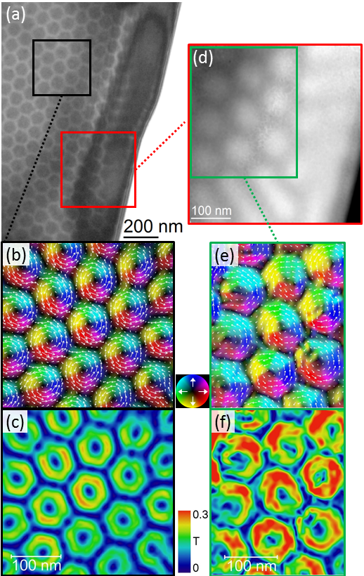
Fig. 2 (a) depicts a L-TEM micrograph in underfocus showing the hexagonal skyrmion lattice as dark contrast, which is one image of the focal series used for in-line holography reconstruction of the object exit wave in amplitude and phase (see Sect. III for acquisition and reconstruction parameters). The projected in-plane components of magnetic induction () were computed from the spatial derivative of the reconstructed phase image (Supplemental Material, Eq. (2)). The knowledge of the projected thickness, which we determined by zero-filtered EFTEM, enables us to compute the components averaged along -direction, i.e., . Figs. 2 (b,c) show magnetic induction maps in cylindrical coordinate representation visualizing the spin texture of the skyrmions by (Fig. 2 (b)) and their donut-shaped magnitude by . Likewise, we observed magnetic induction maps (Figs. 2 (e,f)) from a phase image reconstructed by off-axis EH (Fig. 2 (d)) on the same nanoplate. Comparing the results of the two holographic methods, we measure a slightly higher magnetic induction with a slightly higher spatial resolution in the case of off-axis holography. However, we consistently observe a reduction of the -fields () with respect to the -invariant case () obtained from magnetostatic simulations. Note that we observe similar reductions in a variety of FeGe samples subject to different preparation histories (e.g., as-synthesized nanocrystals, FIB lamellas). Consequently, we can exclude the presence of a non-magnetic surface layer of approximately as the principle reduction mechanism. In order to clarify the origin of the reduced values a 3D reconstruction of the magnetic induction by means of electron holographic tomography Wolf et al. (2015) would be required.
In case of the skyrmionic lattice a tomographic investigation of the 3D modulation is currently experimentally unfeasible, because this necessitates an externally applied out-of-plane magnetic field to be tilted with the sample. In the current experimental setup, the skyrmions align along the magnetic field of the objective lens which has a fixed orientation along the optical axis. In order to overcome these pertaining experimental challenges in-situ magnetic vector field application devices and auxiliary magnetic signals such as EMCD Schattschneider et al. (2006); Schneider et al. (2016); Pohl et al. (2017); Edström et al. (2016) would be helpful. In the following, we therefore resort to acquiring a tilt series of the helical phase stabilizing without applied external field. A representative holographic -field reconstruction of the helical phase is depicted in Fig. 3 (a,b). Accordingly, we observe sinusoidal modulations of the projected lateral -field component with a period of corresponding to spiral magnetic textures aligned in plane (see the Supplemental Material, Suppl. VI). Unfortunately, upon tilting rather large local variations occur in the phase images (e.g., bending fringes visible in the inset of Fig 3 (a)) that are related to changes in the dynamic scattering conditions of the thick crystalline sample in the region of interest (ROI). Likewise, the phase images taken at room temperature required to determine the thickness maps for each tilt, suffer from dynamical diffraction contrast and need to be treated with care (see the Supplemental Material, Suppl. V). After normalizing the projected magnetic fields with corresponding thickness maps, we consistently observe a reduction of the -fields () with respect to the -invariant case () as determined in the case of the skyrmion texture. Consequently, a similar 3D modulation as for the skyrmion lattice is expected under field-free conditions.
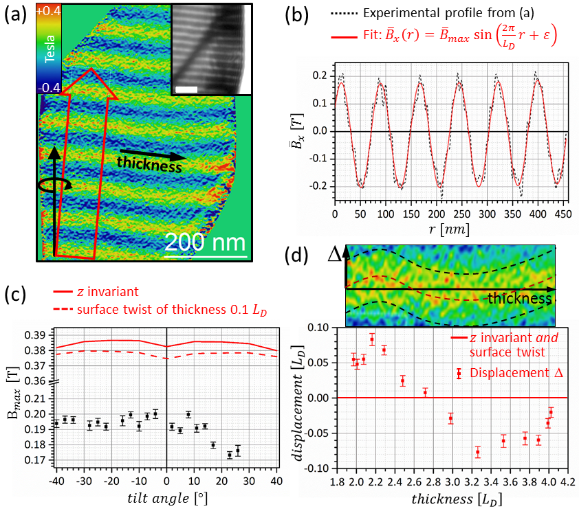
To gain more insight in the underlying spin texture, we analyze the magnetic contrast as function of the tilt angles (Fig. 3 (c)). In the investigated nanoplatelet, the helices are aligned almost parallel to the tilt axis (mistilt of 5° as depicted in Fig. 3 (a)). This orientation is well-suited to identify any 3D spin modulation, such as the previously discussed mixing of helical (i.e., Bloch type) and cycloic (N el type) spiral spin textures in the chiral surface twist, as additional contrast modulation of the stripe pattern in the tilt series. For the contrast measurement, we shifted the ROI in each phase image of the tilt series such that the same mean thickness of was achieved. This suppresses the possible influence of the thickness on the projected fields. The tilt series show a nearly constant value of for tilt angles from -40° to 12° and a strong drop by more than at higher tilt angles. Two different scenarios have been evaluated to clarify the 3D spin configuration: (i) in case of a pure helical spiral without surface twist (solid red line) and upon tilting, the thickness-normalized fringe contrast is almost constant except for a slight modulation around zero tilt due to the above-mentioned mistilt of -7°. This also causes a reduction of from to . (ii) Cycloic-like modulations in a surface twist layer with a thickness of lead mainly to an additional contrast damping (dashed red line) of approximately percent, which is, however, significantly smaller than experimentally observed (Fig. 3 (c)). The measured reduction of the projected fields may only be explained by additional -dependent modulations, spanning larger sections of the film. Evaluating the local fringe position (lateral phase) in a representative induction map from the tilt series (cf. Fig. 3 (a)) and correlating the latter with the corresponding thickness map, we also observed lateral in-plane) displacements of the helical stripes as a function of the overall thickness (see Fig. 3 (d) and scheme above). Such an undulation points to a lateral shift of the helix as a function of the -coordinate, which in turn would on the one hand lead to an additional contrast damping, while on the other hand, would explain the observed asymmetric dependence of the contrast on the tilt angle (Fig. 3 (c)). Such surface-related modulations of the spin texture may be stabilized by additional (surface) anisotropies in the above free energy functional.
In summary, we carried out a quantitative electron holographic reconstruction of the projected in-plance magnetic induction in examined under various tilt directions. We show that these projected magnetic fields are significantly smaller than the fields expected for both -invariant Bloch Skyrmions and the theoretic predictions of chiral surface twists in the thin surface layers of such helimagnets. Although this finding cannot be accounted for by any present model of spin structures, it clearly shows that the underlying magnetic structure substantially deviates from that of a regular Bloch skyrmion in major sections of the film in -direction. Analyzing the thickness dependence of the projeted in-plane field pattern of the helical phase further reveals modulations of this structure also in the --plane. Hence, rather than supporting the model of a homogeneous skyrmion lattice, the results of the present investigations can only be understood by assuming modulations of the skyrmionic structure in all three dimensions throughout the helimagnetic film.
Acknowledgements.
We thank T. Gemming for providing to us the Gatan double tilt liquid nitrogen cooling holder. The authors are indebted to A. P hl and T. Sturm for the preparation of the TEM samples. We thank U. R ler, A. Leonov and A. Bogdanov for fruitful discussions. This research is supported by NSF grant ECCS-1609585. MJS also acknowledges support from the NSF Graduate Research Fellowship Program grant number DGE-1256259. AL and DW have received funding from the European Research Council (ERC) under the Horizon 2020 research and innovation programme of the European Union (grant agreement No 715620).References
- Bogdanov and Hubert (1994) A. N. Bogdanov and A. Hubert, Journal of Magnetism and Magnetic Materials 138, 255 (1994).
- Nagaosa and Tokura (2013) N. Nagaosa and Y. Tokura, Nature Nanotechnology 8, 899 (2013).
- Kanazawa et al. (2017) N. Kanazawa, S. Seki, and Y. Tokura, “Noncentrosymmetric Magnets Hosting Magnetic Skyrmions,” (2017).
- Dzyaloshinsky (1958) I. Dzyaloshinsky, Journal of Physics and Chemistry of Solids 4, 241 (1958).
- Moriya (1960) T. Moriya, Physical Review 120, 91 (1960).
- Heisenberg (1926) W. Heisenberg, Zeitschrift für Physik 38, 411 (1926).
- Nayak et al. (2017) A. K. Nayak, V. Kumar, T. Ma, P. Werner, E. Pippel, R. Sahoo, F. Damay, U. K. Rößler, C. Felser, and S. S. P. Parkin, Nature 548, 561 (2017).
- Kézsmárki et al. (2015) I. Kézsmárki, S. Bordács, P. Milde, E. Neuber, L. Eng, J. White, H. Rønnow, C. Dewhurst, M. Mochizuki, K. Yanai, H. Nakamura, D. Ehlers, V. Tsurkan, and A. Loidl, Nature Materials 14, 1116 (2015).
- Heinze et al. (2011) S. Heinze, K. von Bergmann, M. Menzel, J. Brede, A. Kubetzka, R. Wiesendanger, G. Bihlmayer, and S. Blügel, Nature Physics 7, 713 (2011), arXiv:arXiv:1207.2331v1 .
- Milde et al. (2013) P. Milde, D. Kohler, J. Seidel, L. M. Eng, A. Bauer, A. Chacon, J. Kindervater, S. Muhlbauer, C. Pfleiderer, S. Buhrandt, C. Schutte, and A. Rosch, Science 340, 1076 (2013), arXiv:20 .
- Woo et al. (2016) S. Woo, K. Litzius, B. Krüger, M.-Y. Im, L. Caretta, K. Richter, M. Mann, A. Krone, R. M. Reeve, M. Weigand, P. Agrawal, I. Lemesh, M.-A. Mawass, P. Fischer, M. Kläui, and G. S. D. Beach, Nature Materials 15, 501 (2016), arXiv:1502.07376 .
- Yu et al. (2010) X. Z. Yu, Y. Onose, N. Kanazawa, J. H. Park, J. H. Han, Y. Matsui, N. Nagaosa, and Y. Tokura, Nature 465, 901 (2010).
- Yu et al. (2011) X. Z. Yu, N. Kanazawa, Y. Onose, K. Kimoto, W. Z. Zhang, S. Ishiwata, Y. Matsui, and Y. Tokura, Nature Materials 10, 106 (2011).
- Seki et al. (2012) S. Seki, X. Z. Yu, S. Ishiwata, and Y. Tokura, Science 336, 198 (2012).
- Yu et al. (2013) X. Yu, J. P. DeGrave, Y. Hara, T. Hara, S. Jin, and Y. Tokura, Nano Letters 13, 3755 (2013).
- Rybakov et al. (2013) F. N. Rybakov, A. B. Borisov, and A. N. Bogdanov, Physical Review B - Condensed Matter and Materials Physics 87, 094424 (2013), arXiv:1212.5970 .
- Leonov et al. (2016) A. Leonov, Y. Togawa, T. Monchesky, A. Bogdanov, J. Kishine, Y. Kousaka, M. Miyagawa, T. Koyama, J. Akimitsu, T. Koyama, K. Harada, S. Mori, D. McGrouther, R. Lamb, M. Krajnak, S. McVitie, R. Stamps, and K. Inoue, Physical Review Letters 117, 087202 (2016).
- Leonov et al. (2014) A. O. Leonov, I. E. Dragunov, U. K. Rößler, and A. N. Bogdanov, Physical Review E - Statistical, Nonlinear, and Soft Matter Physics 90, 042502 (2014), arXiv:1407.7409 .
- Rybakov et al. (2016) F. N. Rybakov, A. B. Borisov, S. Blügel, and N. S. Kiselev, New Journal of Physics 18, 045002 (2016), arXiv:1601.05752 .
- Hinshaw et al. (1988) G. A. Hinshaw, R. G. Petschek, and R. A. Pelcovits, Physical Review Letters 60, 1864 (1988).
- Glogarová et al. (1997) M. Glogarová, E. Górecka, L. Leječek, and H. Sverenyák, Molecular Crystals and Liquid Crystals Science and Technology. Section A. Molecular Crystals and Liquid Crystals 301, 325 (1997).
- Wilson et al. (2013) M. N. Wilson, E. A. Karhu, D. P. Lake, A. S. Quigley, S. Meynell, A. N. Bogdanov, H. Fritzsche, U. K. Rößler, and T. L. Monchesky, Physical Review B 88, 214420 (2013).
- Meynell et al. (2014) S. A. Meynell, M. N. Wilson, H. Fritzsche, A. N. Bogdanov, and T. L. Monchesky, Physical Review B 90, 014406 (2014).
- Zheng et al. (2017) F. Zheng, F. N. Rybakov, A. B. Borisov, D. Song, S. Wang, Z.-A. Li, H. Du, N. S. Kiselev, J. Caron, A. Kovács, M. Tian, Y. Zhang, S. Blügel, and R. E. Dunin-Borkowski, arXiv , 1706.04654 (2017), arXiv:1706.04654 .
- Park et al. (2014) H. S. Park, X. Yu, S. Aizawa, T. Tanigaki, T. Akashi, Y. Takahashi, T. Matsuda, N. Kanazawa, Y. Onose, D. Shindo, A. Tonomura, and Y. Tokura, Nature Nanotechnology 9, 337 (2014).
- Kovács et al. (2016) A. Kovács, Z.-A. Li, K. Shibata, and R. E. Dunin-Borkowski, Resolution and Discovery 1, 2 (2016).
- Shibata et al. (2017) K. Shibata, A. Kovács, N. S. Kiselev, N. Kanazawa, R. E. Dunin-Borkowski, and Y. Tokura, Physical Review Letters 118, 087202 (2017), arXiv:1606.05723 .
- Jin et al. (2017) C. Jin, Z.-A. Li, A. Kovács, J. Caron, F. Zheng, F. N. Rybakov, N. S. Kiselev, H. Du, S. Blügel, M. Tian, Y. Zhang, M. Farle, and R. E. Dunin-Borkowski, Nature Communications 8, 15569 (2017).
- Bogdanov and Yablonskii (1989) A. N. Bogdanov and D. A. Yablonskii, Zh. Eksp. Teor. Fiz. 95, 178 (1989).
- Lebech et al. (1999) B. Lebech, J. Bernhard, and T. Freltoft, Journal of Physics: Condensed Matter 1, 6105 (1999), arXiv:arXiv:1011.1669v3 .
- Lubk et al. (2016) A. Lubk, K. Vogel, D. Wolf, J. Krehl, F. Röder, L. Clark, G. Guzzinati, and J. Verbeeck, in Advances in Imaging and Electron Physics, Vol. 197 (Elsevier, 2016) pp. 105–147.
- Lichte et al. (2013) H. Lichte, F. Börrnert, A. Lenk, A. Lubk, F. Röder, J. Sickmann, S. Sturm, K. Vogel, and D. Wolf, Ultramicroscopy 134, 126 (2013).
- Wolf et al. (2015) D. Wolf, L. A. Rodriguez, A. Beche, E. Javon, L. Serrano, C. Magen, C. Gatel, A. Lubk, H. Lichte, S. Bals, G. Van Tendeloo, A. Fernandez-Pacheco, J. M. De Teresa, and E. Snoeck, Chemistry of Materials, Chemistry of Materials 27, 6771 (2015).
- Schattschneider et al. (2006) P. Schattschneider, S. Rubino, C. Hébert, J. Rusz, J. Kuneš, P. Novák, E. Carlino, M. Fabrizioli, G. Panaccione, and G. Rossi, Nature 441, 486 (2006).
- Schneider et al. (2016) S. Schneider, D. Pohl, S. Löffler, J. Rusz, D. Kasinathan, P. Schattschneider, L. Schultz, and B. Rellinghaus, Ultramicroscopy 171, 186 (2016).
- Pohl et al. (2017) D. Pohl, S. Schneider, P. Zeiger, J. Rusz, P. Tiemeijer, S. Lazar, K. Nielsch, and B. Rellinghaus, Scientific Reports 7, 934 (2017).
- Edström et al. (2016) A. Edström, A. Lubk, and J. Rusz, Physical Review Letters 116, 127203 (2016).