Thixotropic flow past a cylinder
Abstract
We study the flow of a thixotropic fluid around a cylinder. The rheology of the fluid is described by means of a structural viscoplastic model based on the Bingham constitutive equation, regularised using the Papanastasiou regularisation. The yield stress is assumed to vary linearly with the structural parameter, which varies from zero (completely broken structure) to one (fully developed skeleton structure), following a first-order rate equation which accounts for material structure break-down and build-up. The results were obtained numerically using the Finite Element Method. Simulations were performed for a moderate Reynolds number of 45, so that flow recirculation is observed behind the cylinder, but vortex shedding does not occur. The effects of the Bingham number and of the thixotropy parameters are studied. The results show that the viscous character of the flow can be controlled within certain limits through these parameters, despite the fact that the Reynolds number is fixed.
keywords:
thixotropy , viscoplasticity , flow past a cylinder , Papanastasiou regularisationThis is the accepted version of the article published in: Journal of Non-Newtonian Fluid Mechanics 220 (2015) 44–56, doi:10.1016/j.jnnfm.2014.08.008
©2017. This manuscript version is made available under the CC-BY-NC-ND 4.0 license http://creativecommons.org/licenses/by-nc-nd/4.0/
1 Introduction
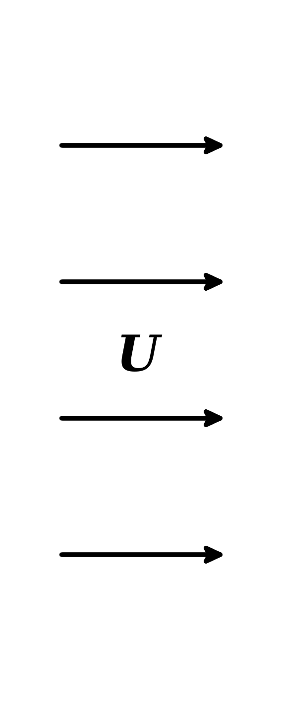
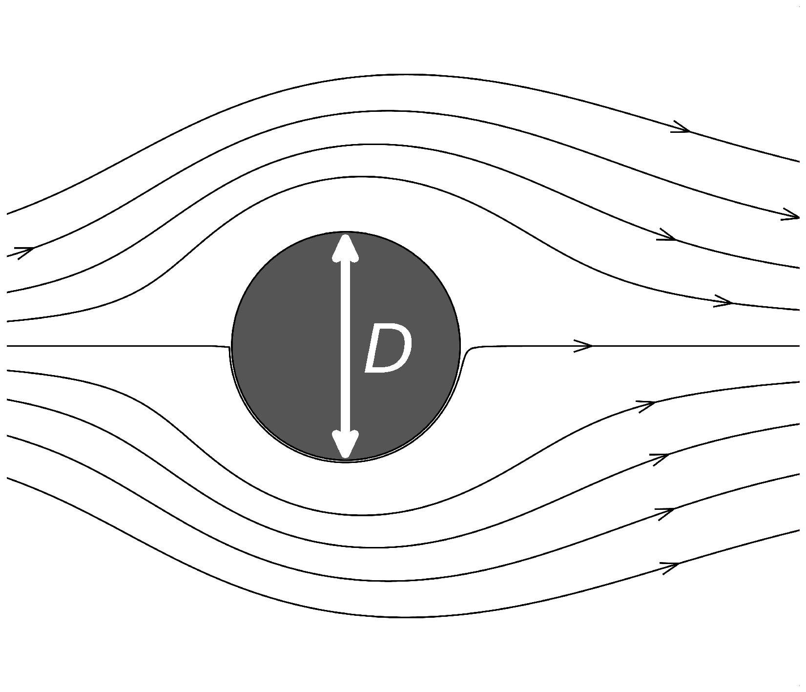
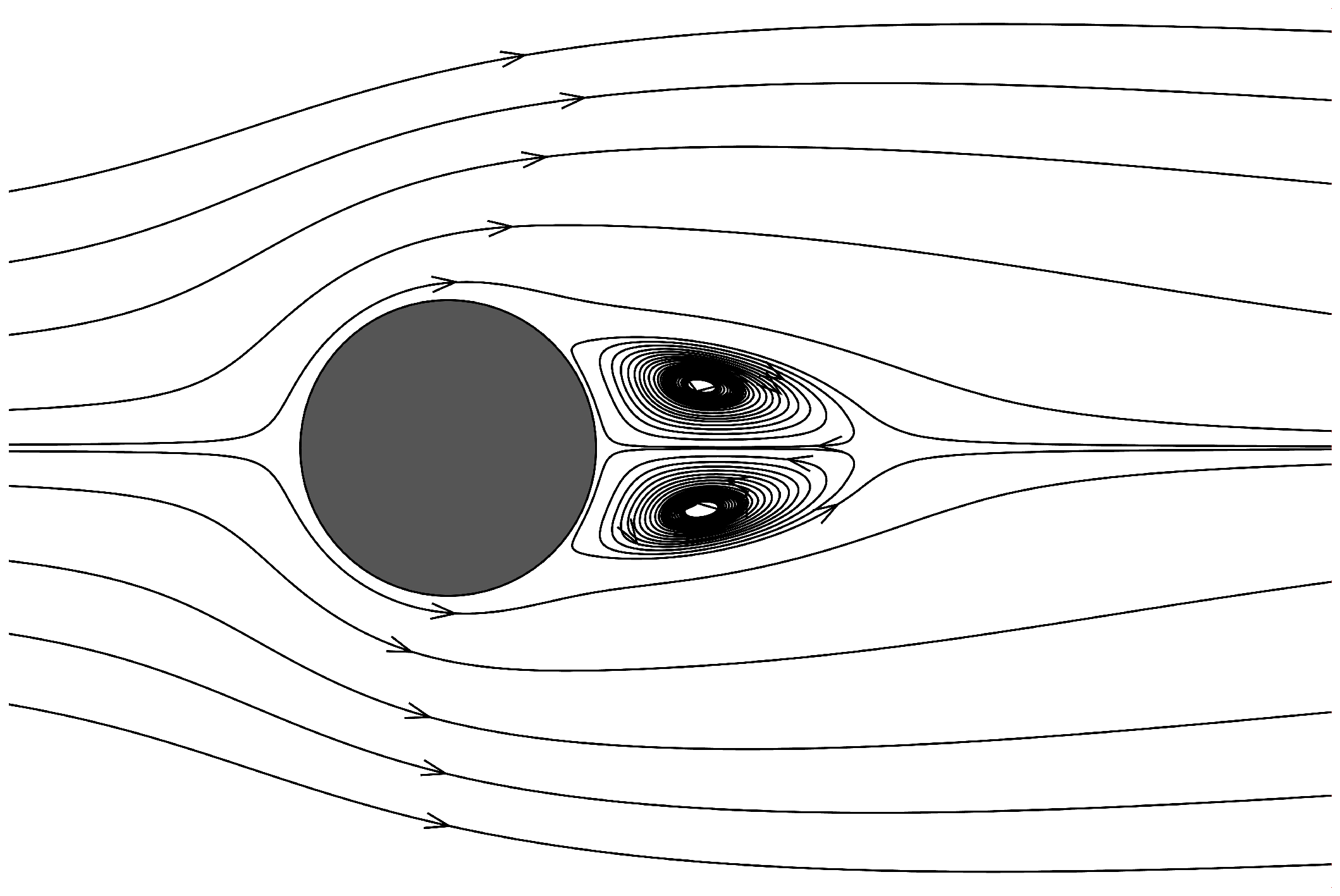
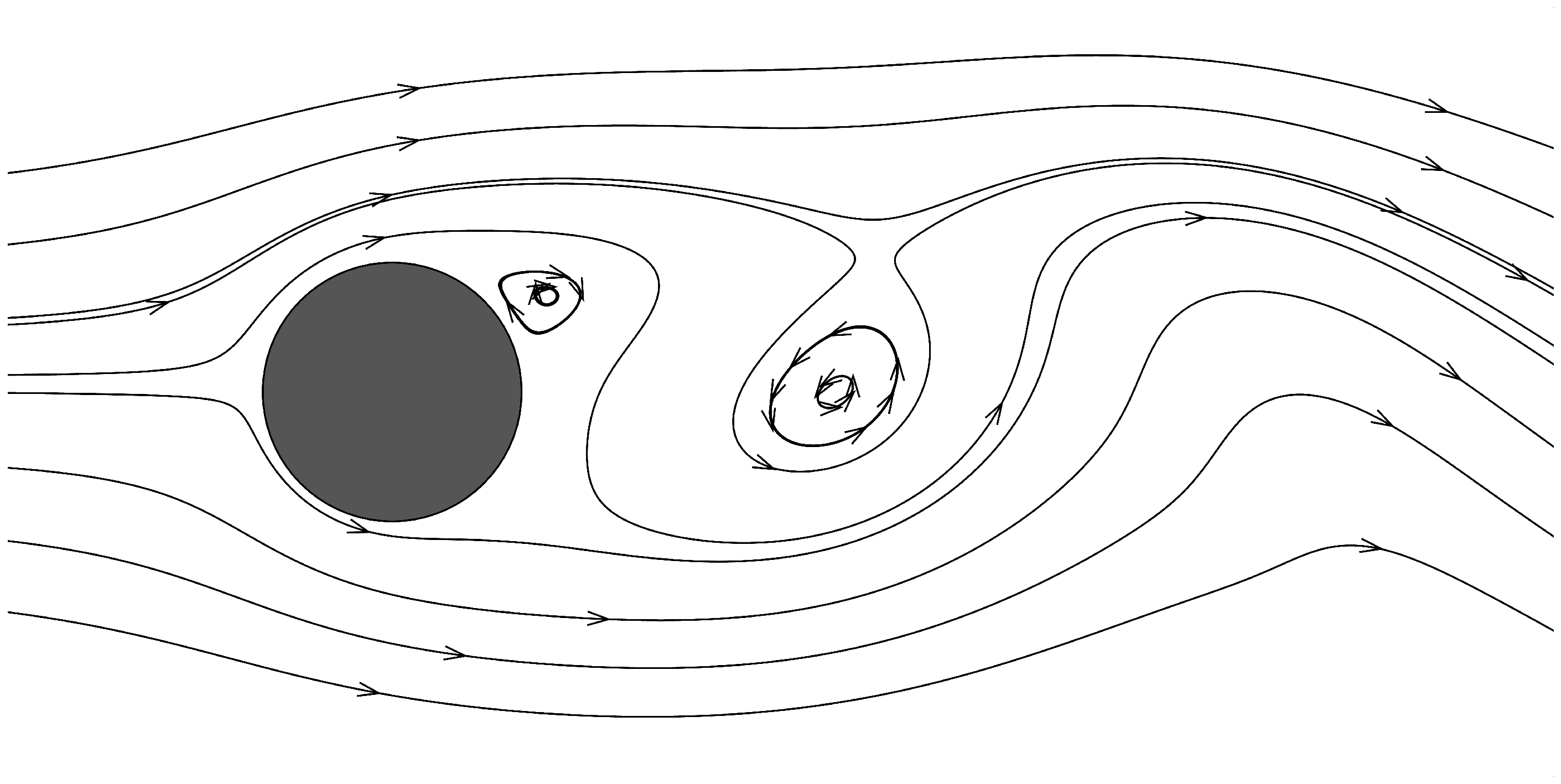
The flow past a cylinder is of high theoretical and practical importance, and thus the Newtonian flow case has been studied extensively. The main results are included in a review paper by Williamson [1]. The characteristics of the flow field strongly depend on the Reynolds number, which is defined as where and are the fluid density and viscosity respectively, is the main stream velocity, and is the cylinder diameter (see Fig. 1). Up to a Reynolds number of 5, the flow is characterised as creeping and no separation is exhibited (Fig. 1()). However, in the range , flow separation is observed and a symmetric pair of recirculation bubbles appears behind the cylinder (Fig. 1(a)), which increase in size with the Reynolds number. A further increase in the Reynolds number () causes the flow to become unsteady, with periodic vortex shedding behind the cylinder (Fig. 1(b)). If the Reynolds number is further increased then transition to turbulence begins to take place. However, in the present study we limit ourselves to the laminar flow regime.
Viscoplastic flow past a cylinder is less studied, but there do exist a number of published results. Most of these results concern creeping flow, and are relatively recent, with the exception of the early theoretical work of Adachi and Yoshioka [3]. About a decade ago computational studies began to appear on creeping viscoplastic flow around a cylinder. There are two basic configurations: flow in an infinite medium [4, 5] and flow between two parallel plates [6, 7, 8]. The two configurations are equivalent when the yielded zone which surrounds the cylinder does not extend up to the plates. There exist also studies of creeping viscoplastic flow around cylinders of non-circular cross section [9, 10], but this is beyond the scope of the present work. Flow at non-zero Reynolds numbers was studied recently by Mossaz et al. [11, 12], and to the best of our knowledge these are the only published results.
Usually, viscoplasticity is accompanied by other rheological phenomena such as thixotropy and/or viscoelasticity. Such behaviour was exhibited by the materials used in the few available experimental studies of viscoplastic flow around a cylinder [13, 14]. A recent computational study which includes the effects of viscoplasticity, thixotropy and viscoelasticity was conducted by Fonseca et al. [15]. That study is limited to creeping flow. The aim of the present work is to isolate the effects of thixotropy and yield stress in the case of non-zero Reynolds number flows which may exhibit recirculation bubbles behind the cylinder.
The rest of the paper is organised as follows: In Section 2 the equations which govern the flow are presented. In Section 3 the domain, boundary conditions and finite element solution method are described. In Section 4 the results are presented, and the paper ends with some conclusions in Section 5.
2 Governing equations
The flow is governed by the continuity and momentum equations for incompressible, constant-density flow:
| (1) |
| (2) |
where is the velocity vector, is the pressure, is the density (a constant) and is the deviatoric stress tensor.
In the present work, the model material under study is assumed to have an internal structure which governs the behaviour of the material and can change over time. The components of the material form a structure, which is capable of withstanding loads up to a limit without permitting flow. Flow occurs when the magnitude of the deviatoric stress tensor exceeds a threshold value, the yield stress . The yield stress is assumed to depend on the current state of the structure of the material. It is also assumed that, when the material flows, i.e. the yield stress is exceeded, then the structure starts to break down. This is a time-dependent process, with the rate of breakdown being proportional to the rate of shear, and will lead to partial or complete breakdown of the structure. Partial breakdown of the structure reduces the ability of the material to sustain loads, i.e. it reduces the yield stress. The structure also has a tendency to recover with time, thus increasing the yield stress. This tendency is independent of the shear rate. These two mechanisms compete with each other.
It is customary to associate the state of the structure with a dimensionless variable, denoted here, which equals 1 when the material is completely structured and 0 when the structure is completely broken. All intermediate states correspond to . Our model material is assumed to follow a simple relationship between the structure parameter and the yield stress:
| (3) |
where is the current yield stress of the material at point at time , is the instantaneous value of the structure parameter at that point, and is the maximum yield stress, when the material is fully structured (). According to the above equation, the thixotropic material is no longer viscoplastic when the structure is completely broken (). More complicated constitutive relations can be constructed which assume that the rest of the rheological parameters are also functions of ; indeed several such relations have been suggested in the literature, and the review paper by Mewis and Wagner [16] contains a list with many of them. By using the simple Eq. (3) we isolate the effects of thixotropy on the most important parameter, the yield stress.
At stresses higher than the yield stress, when the material flows, it is assumed that a linear relationship is exhibited between the stress and the rate of strain, i.e. the material is assumed to be of the Bingham type:
| (4) |
where is the plastic viscosity, is the rate-of-strain tensor, and is its magnitude. This constitutive equation applies only where the material flows, whereas in unyielded regions () there is no deformation. This is a simplified version of the models of Tiu and Boger [17] and Houska [18, 19], who assumed a fluid of the Herschel-Bulkley type and that both the yield stress and the plastic viscosity are linear or affine functions of .
As already mentioned, the evolution of the structure is due to two mechanisms: a shear-driven breakdown mechanism, and a recovery mechanism. In the present work, this evolution is described by the following simple equation, which was originally proposed by Moore [20] and is a simplified version of the model used in [21]:
| (5) |
where is the rate of change of within a particle of the material which moves with the flow. The recovery term is proportional to , so that recovery ceases when the structure has fully recovered (, and the constant of proportionality is the recovery parameter , with units of [time]-1. The breakdown term is proportional to , so that at complete breakdown () there is no more breakdown, and also to the magnitude of the rate of strain tensor, since breakdown is assumed to be a shear-driven mechanism. The constant of proportionality is the breakdown parameter , which is dimensionless. In an Eulerian frame of reference, Eq. (5) is written as
| (6) |
The structure of a particle which experiences a constant strain rate will eventually reach an equilibrium where and the rate of breakdown is matched by the rate of build-up. The equilibrium value of can be found from Eq. (5):
| (7) |
By substituting Eq. (7) into Eq. (4) we get the equilibrium value of the magnitude of the stress as a function of the strain rate:
| (8) |
If we dedimensionalise the stresses by , and the strain rate and by then the above equation can be written in non-dimensional form as
| (9) |
where the tilde (~) denotes dedimensionalised quantities, and is the Bingham number, defined by
| (10) |
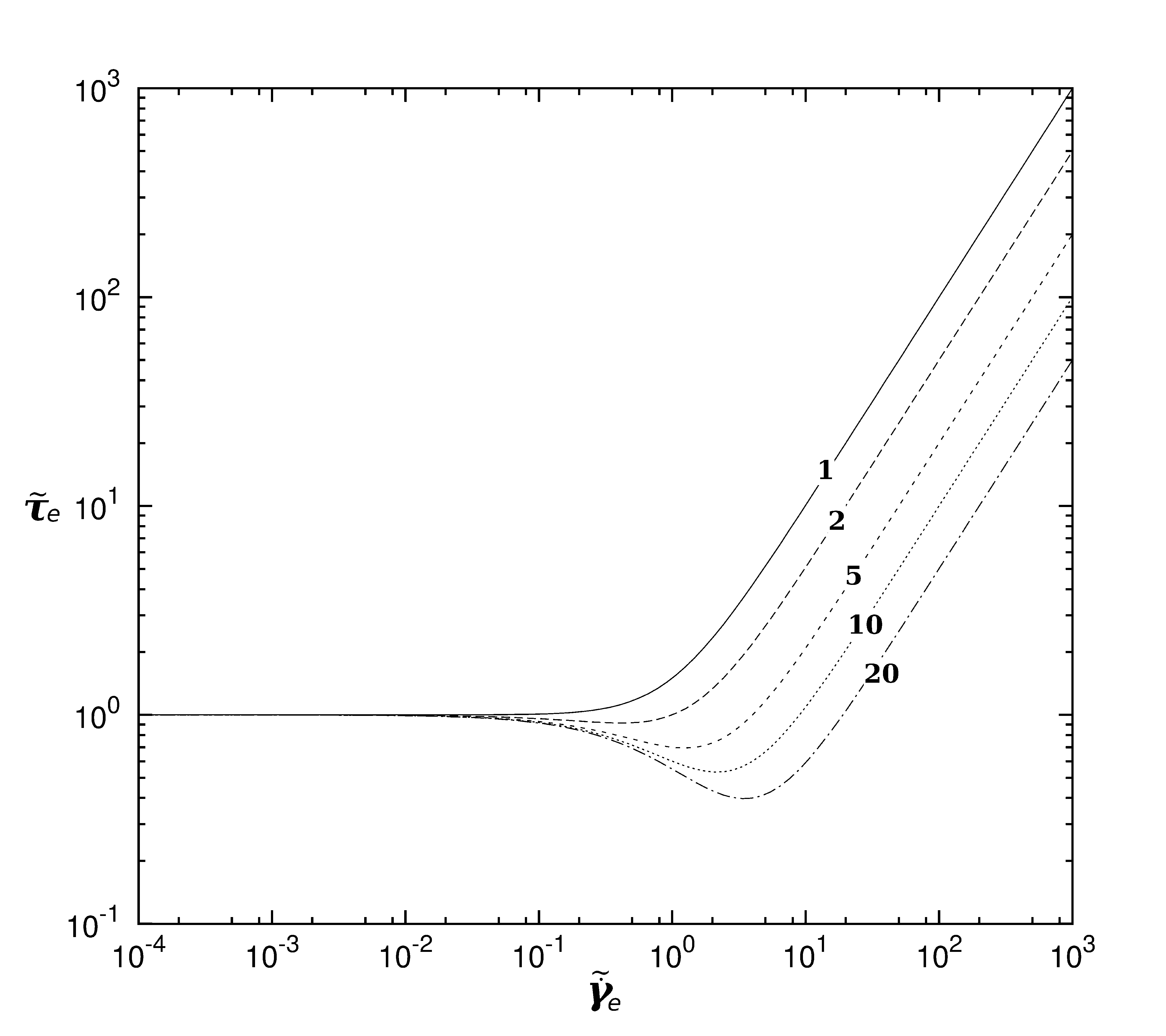
The function (Eq. (9)) is plotted against in Figure 2, for the case . Since, according to Eq. (4), the magnitude of the total stress is due to two components (the yield stress and the viscous part ), the shapes of the curves shown in Fig. 2 reflect the relative balance between these two components at each value of the shear rate . In particular, at low shear rates the viscous component is small and the total stress is approximately equal to the yield stress , which in turn is nearly equal to since at low shear rates the breakdown is nearly zero and the material is nearly fully structured (, Eq. (7)). Thus at low rates of strain all curves in Fig. 2 converge to . Then, if is progressively increased, the structure breakdown rate also increases and thus is reduced below 1 and the yield stress falls, according to Eq. (3). As long as dominates the total stress , this causes also the total stress to fall, which can be seen in Fig. 2 where falls below 1, especially at higher Bingham numbers where the yield stress is more dominant. However, as is increased further the viscous part of the stress starts to become significant, and quickly becomes the dominant stress component: . Thus at large values of , increases again, eventually with a slope of , as can be seen from Eq. (9). At some point in between the stress reaches its minimum value. Therefore each of the curves of Figure 2 exhibits a minimum at some value of . Experimental studies [22] show that real thixotropic materials may exhibit this sort of behaviour.
It may be noticed that within an unyielded region = 0 and thus there is only recovery (no structure breakdown), and Eq. (5) becomes:
| (11) |
Assuming that the structure parameter has a value at time , this ordinary differential equation can be solved to calculate the value of as a function of time:
| (12) |
where and are the the nondimensional recovery parameter and time, respectively. Therefore, every time units (or nondimensional time units), the structure recovers by a factor of (the degree of structure breakdown becomes times smaller). Thus can be regarded as a characteristic time scale for structure recovery.
Equations (1) – (2) can be written in nondimensional form, by scaling lengths by , time by , velocities by , and stress and pressure by . We thus obtain the following nondimensional forms:
| (13) |
| (14) |
where
| (15) |
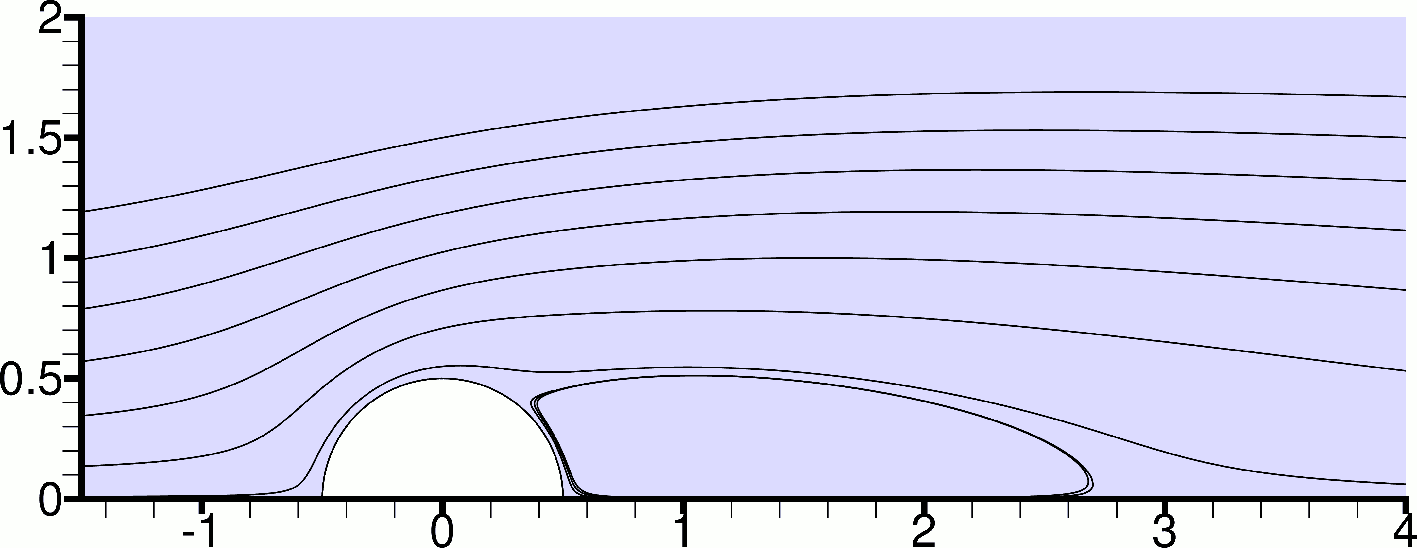
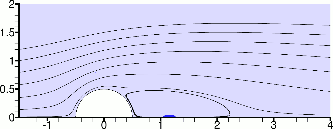
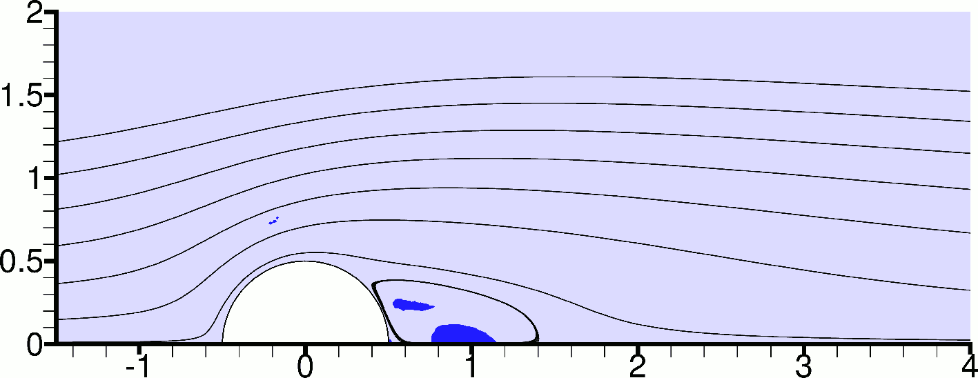
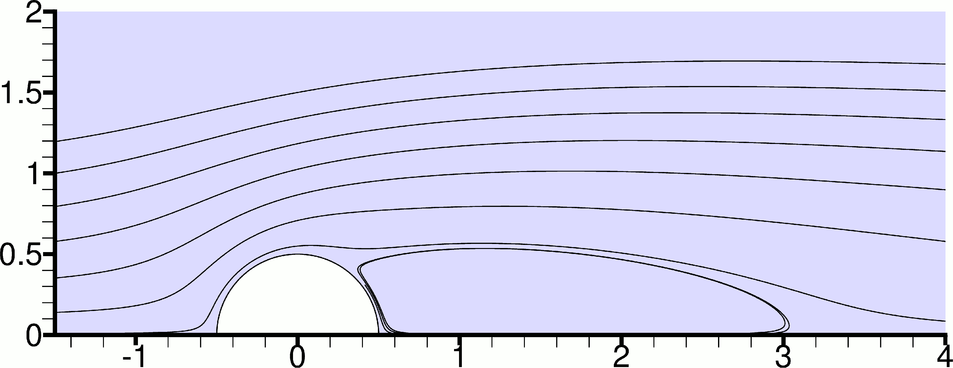
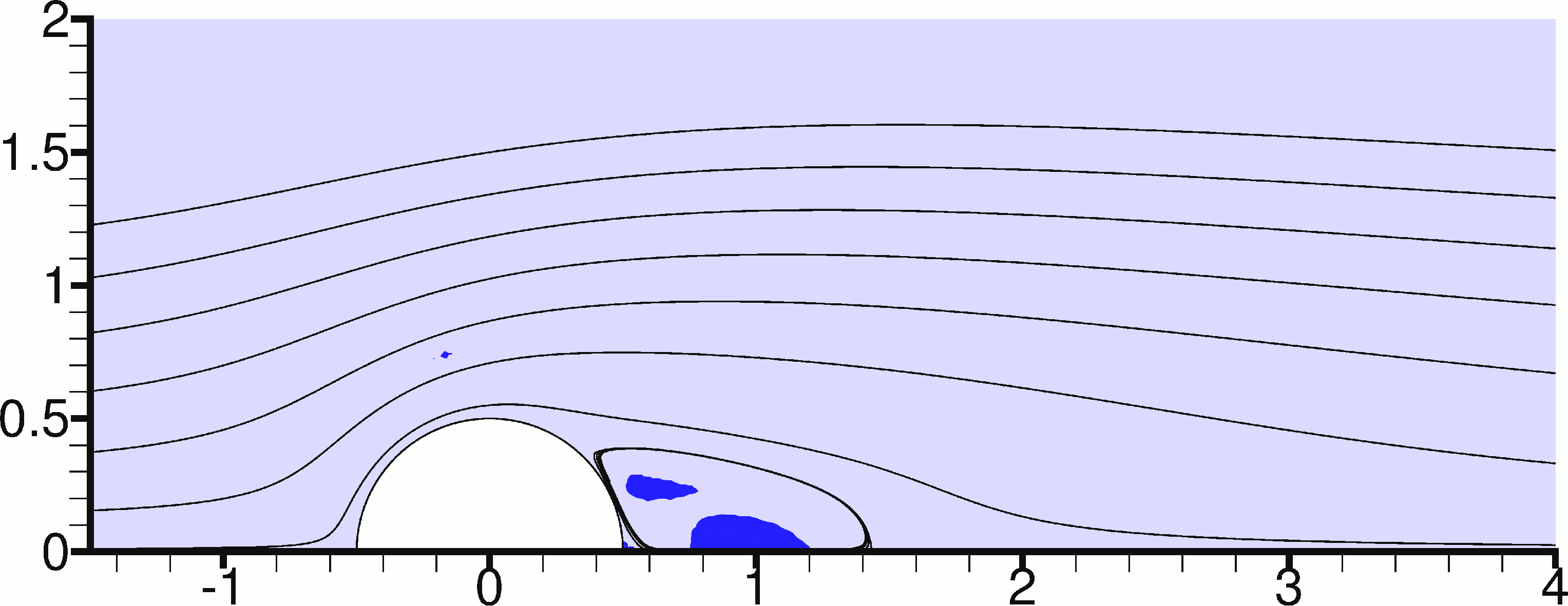
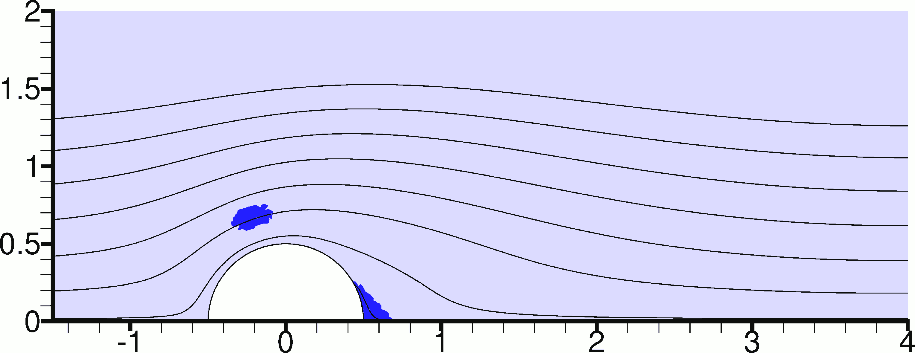
It may be seen that if the and numbers are increased together so that the ratio is kept constant then the term in Eq. (15) becomes less and less important. Eventually it can be seen in Eq. (14) that the flow is influenced only by the number outside the parentheses on the right hand side, and not by the Bingham number which is implicit in the definition of the stress from equation (15). In this case the flow field is actually governed by the ratio , as can be seen by dividing Eq. (14) by . Therefore, the Reynolds and Bingham numbers have opposite effects on the flow, so that increasing one of them has a similar effect as decreasing the other. To illustrate this, we jump ahead for the moment and without yet discussing the numerical method we present in Figure 3 results for Bingham flow without thixotropy, chosen for validation purposes because they match corresponding results in Ref. [11]. Moving from top to bottom, in Figures 3(a) – 3(e) the Bingham number is increased while the Reynolds number is held fixed at . In the Newtonian case (Figure 3(a)) the recirculation bubbles are fairly large, but as the Bingham number is increased they reduce in size and at (Figure 3(e)) the flow has become creeping, without separation. Increasing the Bingham number also causes the formation of unyielded zones (shown shaded) behind the cylinder, which are initially detached from the cylinder and are thus moving with the flow (rigid body motion) but beyond a certain Bingham number they merge and get attached to the cylinder surface, becoming motionless (Figure 3(e)). One can also notice very small unyielded regions above the cylinder (and below, in the symmetric part of the images which is not shown) which grow as is increased. The reader who is familiar with the creeping () viscoplastic flow around a cylinder will notice that increasing the Bingham number makes the flow field more similar to the creeping flow case - see the relevant references in Section 1.
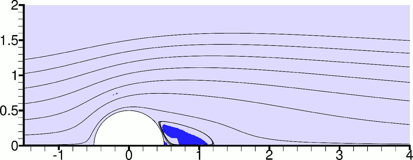
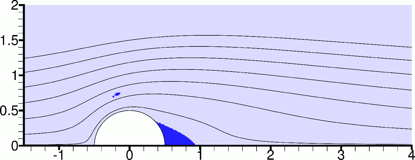
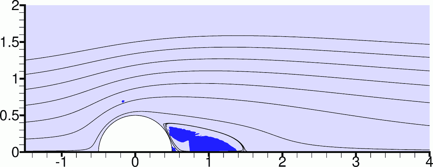
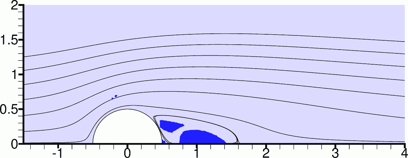
3 Numerical method
The Bingham constitutive equation (4) is discontinuous, separating the material into yielded / unyielded zones whose boundaries are not known a priori. This complicates the numerical solution of the flow. To avoid numerical difficulties we used the customary Papanastasiou regularisation scheme [23]. In fact this approach has been adopted by all the previous studies on viscoplastic flow past a cylinder mentioned in Section 1 except for that of Roquet and Saramito [7], who used an augmented Lagrangian approach, thus directly solving the original Bingham constitutive equation. According to Tokpavi et al. [5] the difference between the results produced by the two methods is rather small. Thus the constitutive equation used here, applicable throughout the material, is the following:
| (16) |
where the constant is the regularisation parameter, which should be large enough so that the original Bingham equation is approximated adequately. We note that in the present study we follow the usual practice of identifying the unyielded regions as those regions where or equivalently ; see Burgos et al. [24] for more information. We note that regularisation implies that unyielded regions are approximated by small, but non-zero rate of strain. The maximum rate of strain in an unyielded region can be calculated by writing Eq. (16) in terms of tensor magnitudes and substituting . Then, after some manipulation and dedimensionalisation the following equation is obtained:
| (17) |
where is the non-dimensional rate of strain at the surfaces where , assumed to be the yield surfaces; the rate of strain is smaller than that in the interior of the unyielded regions. is the non-dimensional regularisation parameter . Eq. (17) has an analytic solution:
| (18) |
where is the Lambert W function [25, 26]. Just to give an idea of the order of for the range of parameters used in the present study, we give some examples for : For {=0.5, =1000}, ; for {=0.5, =10000}, ; for {=5, =1000}, ; and for {=5, =10000}, . The value is about the smallest rate of strain that the regularised model can predict with relative accuracy - for smaller values the error increases significantly.
The governing equations were solved numerically using a mixed Galerkin finite element method. In the present work the focus is on subcritical flow where vortex shedding is not present. Therefore, the flow field is symmetric, with the plane of symmetry being parallel to the main flow, and only half of the domain needs to be modelled. The computational domain is shown in Figure 4. The cylinder, of radius , is centred at point (0,0). Modelling the flow domain up to an outer radius of was considered sufficient for the simulation of unconfined flow, based on the observations of Mossaz et al. [11]. The boundary conditions are also illustrated in Figure 4. A no-slip condition (zero velocity) is applied to the cylinder surface. The left half of the outer circumference of the computational domain is an inlet, where fluid flows horizontally into the domain with a velocity = 1. The incoming fluid is fully structured (). The right half of the outer circumference of the domain is an outlet, where a zero-stress condition is applied. Finally, the bottom of the domain is a symmetry plane and therefore and .

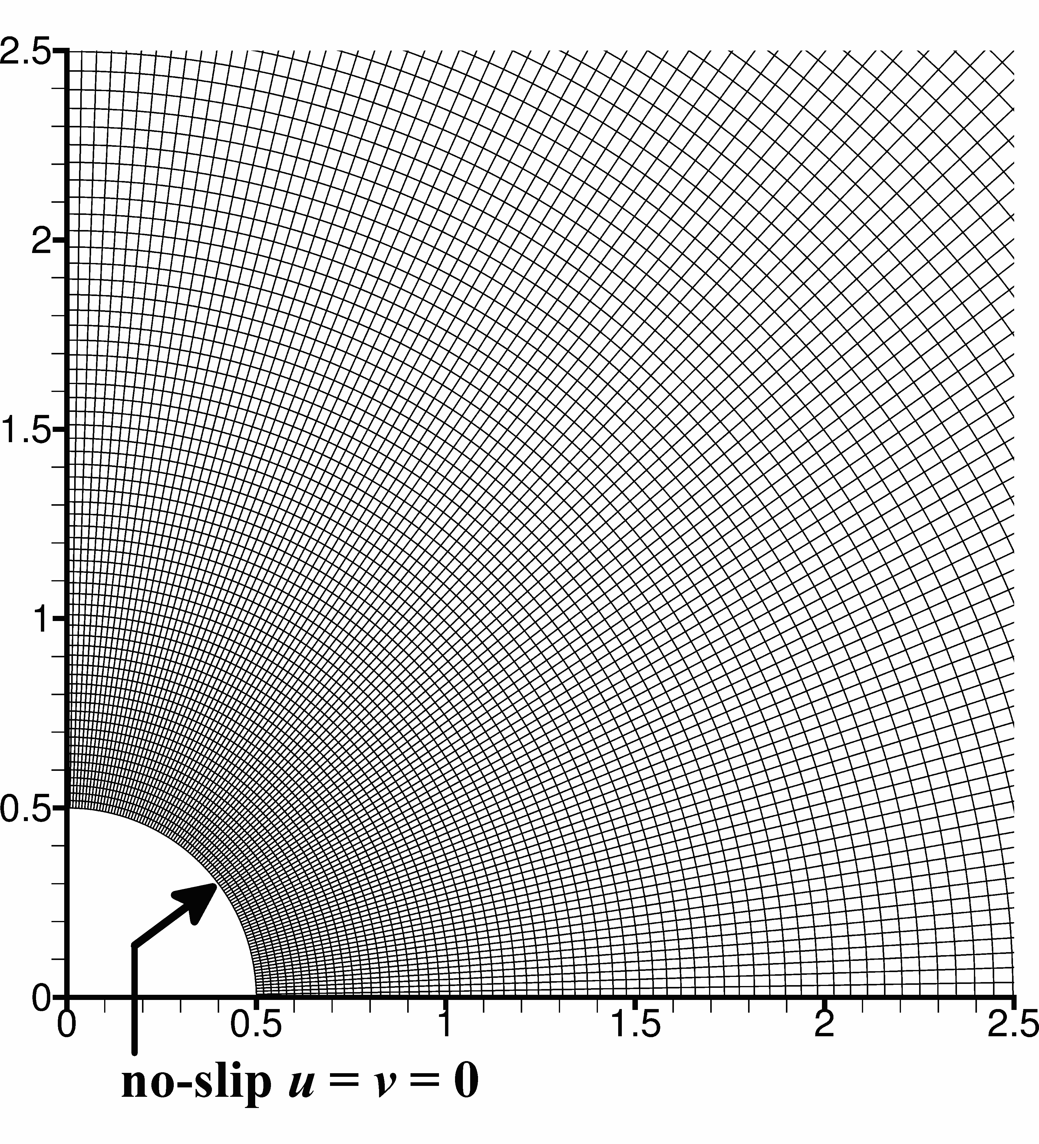
Figure 4 also shows the computational mesh used. The mesh consists of 100 150 mixed finite elements, along the circumferential and radial directions, respectively. Therefore each element spans four grid cells, ordered in a fashion. This mesh is more refined than that used by Mossaz et al. [11], who obtained reliable results that we used for validation of our own results. Each problem is solved as a time-dependent problem until a time of , which was observed to be sufficient to obtain the steady-state solution. The initial condition is that = = 0 and = 1 at = 0. The temporal discretisation scheme employed is the implicit Euler scheme. The Newton-Raphson procedure is used to solve the resulting non-linear algebraic system within each time step, and in each Newton-Raphson step the linear system which arises is solved using the freely available sparse frontal solver MUMPS [27, 28]. Eq. (6) is solved individually within the Newton-Raphson iterative scheme.
A complexity arises from the fact that the transport equation for , Eq. (6), does not contain any diffusion terms. Therefore, without any special treatment, it is anticipated that its numerical solution will produce a field which contains spurious oscillations, and in fact the reader can indeed, in some cases, observe such oscillations in the Figures presented in the next Section. These non-physical oscillations spoil the aesthetics of the solution, but the mean field is unaffected. Although there do exist more elaborate discretisation schemes which prevent the appearance of such oscillations (e.g. [29]), in the present work for simplicity we adopted a more “crude” approach of allowing the oscillations, and just setting the value of equal to 0 or 1 whenever a negative value or a value greater than 1 is produced, respectively.
4 Numerical results
In the present Section, the results will be presented in terms of the non-dimensional form of the variables, but, for simplicity, tildes will be dropped from the corresponding variable names.
The equations that govern the flow involve many parameters: the Reynolds number , the Bingham number , and the thixotropy parameters and . Hence, in order to get the complete picture, one has to assign different values to each of these parameters and repeat the simulations. This produces a prohibitively large number of numerical experiments that have to be performed. For practical reasons therefore we confined our study to the regime where the flow is symmetric, which requires that the Reynolds number is small enough. Numerous studies agree that, for Newtonian flow, the onset of periodic vortex shedding occurs at a critical Reynolds number of (see [1, 30, 31] and references therein). It was therefore decided to fix the Reynolds number at a value of which is close to, but smaller than, this critical Reynolds number in order to have a relatively high Reynolds number but at the same time excluding the possibility of vortex shedding irrespective of the values of the other parameters (). This is because the effect of the Bingham number is to increase the viscous character of the flow, thus increasing the critical Reynolds number beyond the value of 47; thixotropy on the other hand recovers some of the inertial character of the flow, but it cannot make the flow more inertial than in the Newtonian case, that is it cannot reduce the critical Reynolds number below 47.
So, in the following the Reynolds number is fixed at , while two values are assigned to the Bingham number: a low value of , and a medium value of . As will be shown later in this Section, with these two choices of Bingham number the results span both steady-state regimes: Recirculating flow and creeping flow, respectively. Then the effect of the thixotropy parameter is investigated by holding fixed at and varying in the set . Also, the effect of is investigated by holding fixed at and varying in the set . From these results, one can also obtain a feel about the effect of on the flow, because, as discussed in Section 2, the flow characteristics are approximately governed by the ratio . Increasing , increasing , or reducing would make the flow more “viscous” - that is, it would increase the magnitude of the viscous stresses, thus increasing their significance relative to momentum (inertial) fluxes - causing an effect similar to decreasing the Reynolds number; and the opposite action on these parameters would make the flow more “inertial”, causing an effect similar to increasing the Reynolds number. A difference is that, whereas the effect of and on the viscous character of the flow is independent of time, the effect of and is not, because it takes time for structural changes to occur and viscous stresses to increase or decrease due to thixotropy.
The effect of thixotropy will be studied in comparison with the base cases of and without thixotropy, which are plotted in Figure 5. In this and subsequent figures, only half of the physical domain is shown, and we will follow the convention of referring only to the flow features that are visible in the figures. Thus, for example, we will refer to one recirculation bubble, although there is another identical bubble in the symmetric part of the physical domain. With this convention in mind, we make the following observations from Figure 5: Newtonian flow exhibits a very large recirculation bubble, which is anticipated since the flow is close to the onset of vortex shedding. At a Bingham number of 0.5 the recirculation bubble has decreased in size, and a pair of unyielded zones appears behind the cylinder, detached from its surface, and moving at small but non-zero velocities with the flow. Actually, there are two more unyielded zones, which are very small and are difficult to see: one touching the back of the cylinder at the symmetry plane, and one above the cylinder and slightly upstream of it. At a Bingham number of 5, the recirculation bubble has disappeared, and the unyielded zones behind the cylinder have merged into a single zone which is in contact with the cylinder and is therefore motionless, and whose size is rather small. The unyielded zone above the cylinder can be seen to have grown considerably in size. In general, the flow field shown in Figure 5(c) looks a lot more like the flow field of creeping viscoplastic flow, which is described in references such as [4, 5, 6, 7, 8]. Thus although the Reynolds number is fixed at , the choice of two Bingham numbers and allows the investigation of two different flow regimes.
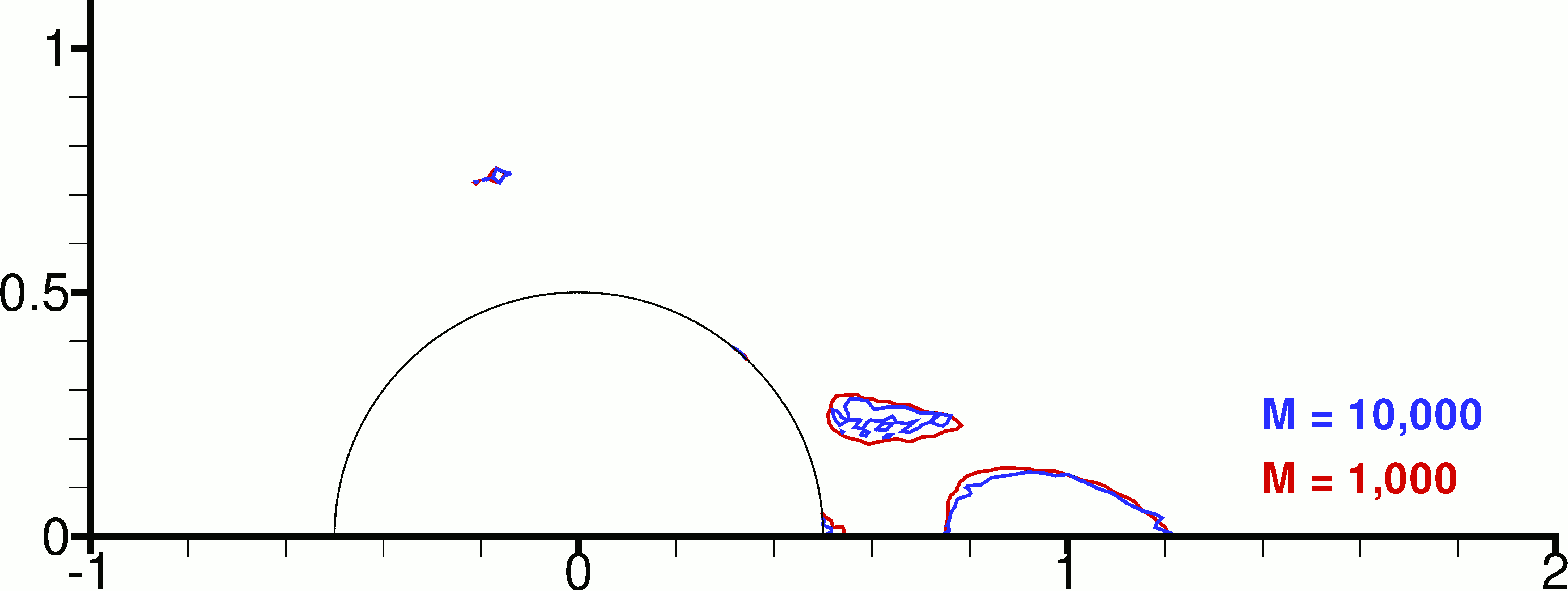
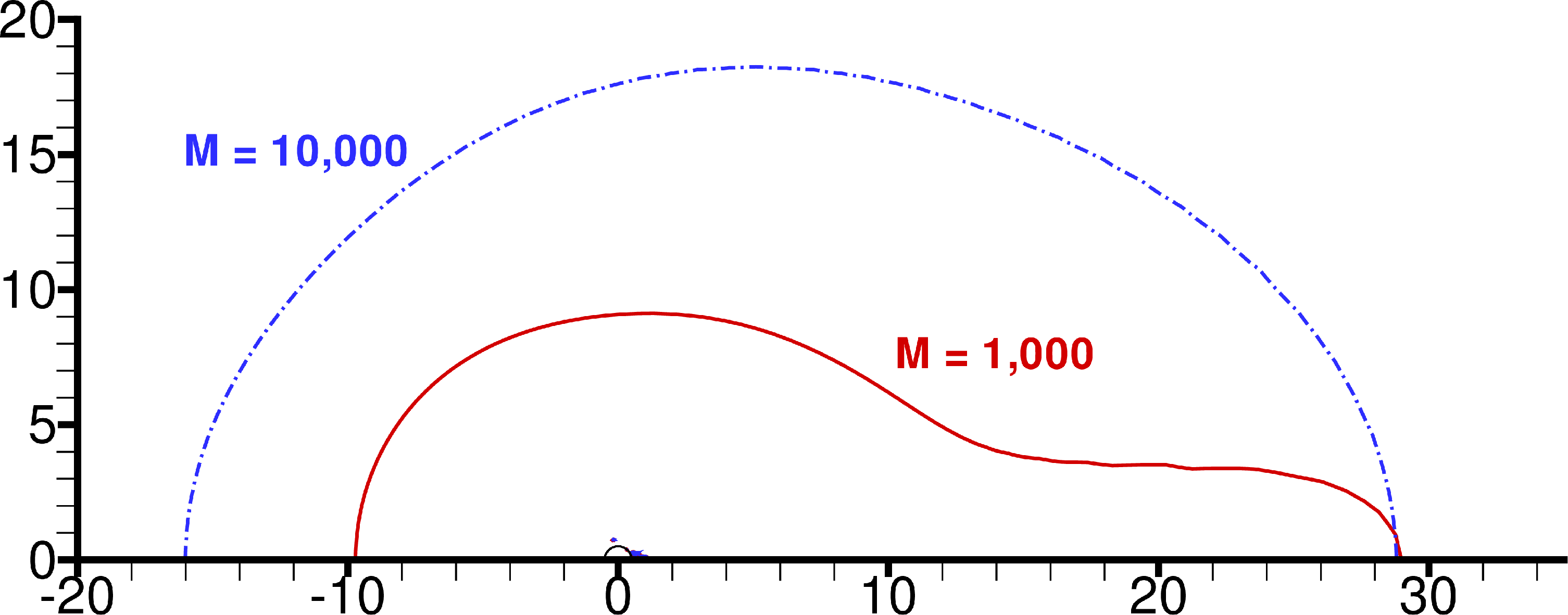
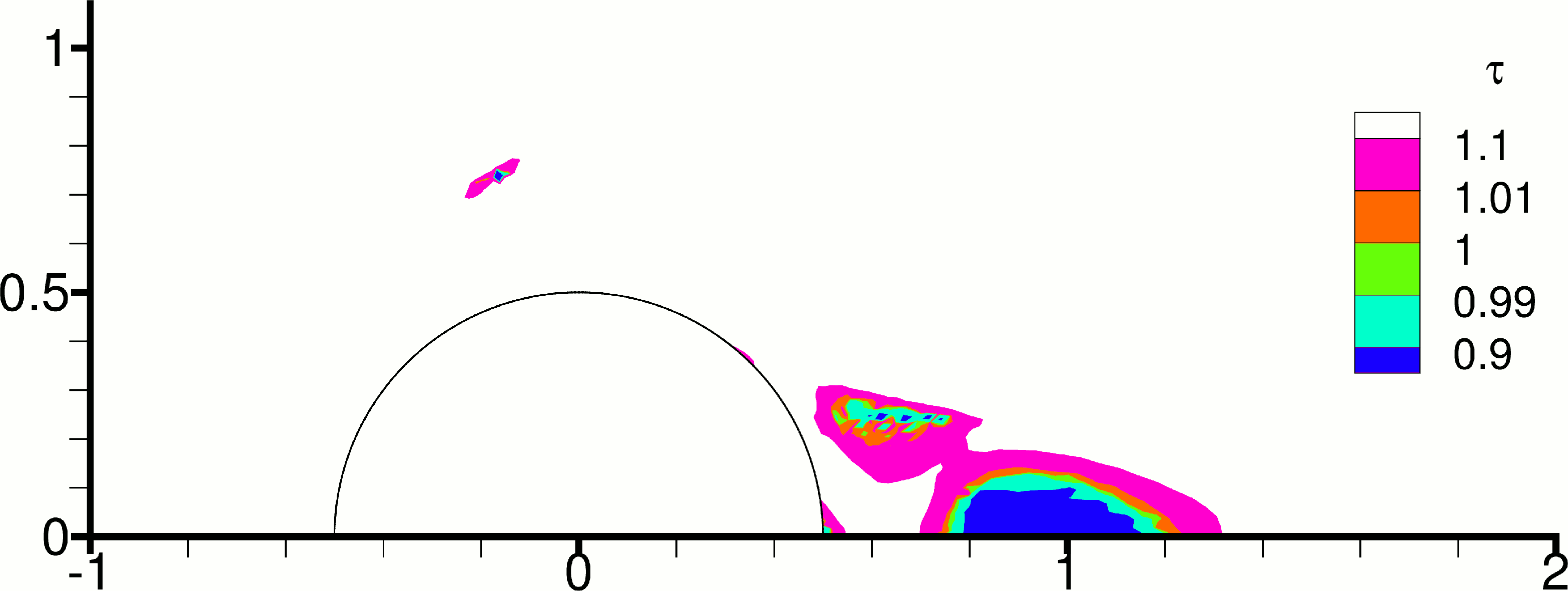
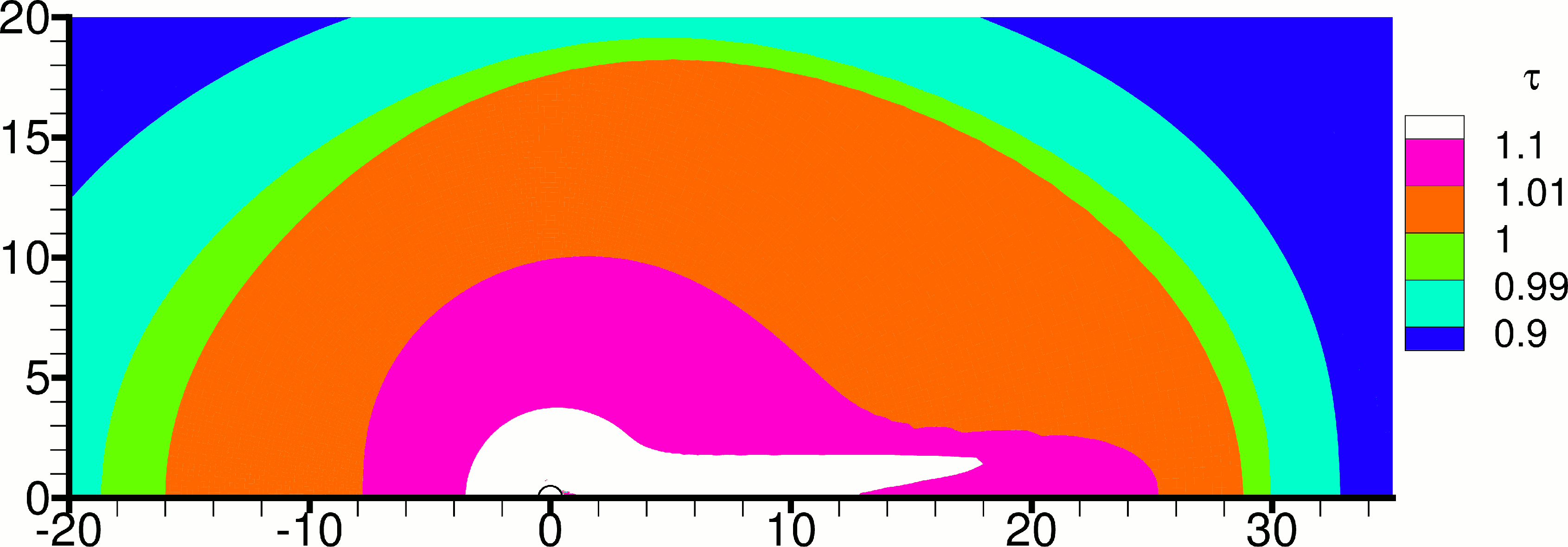
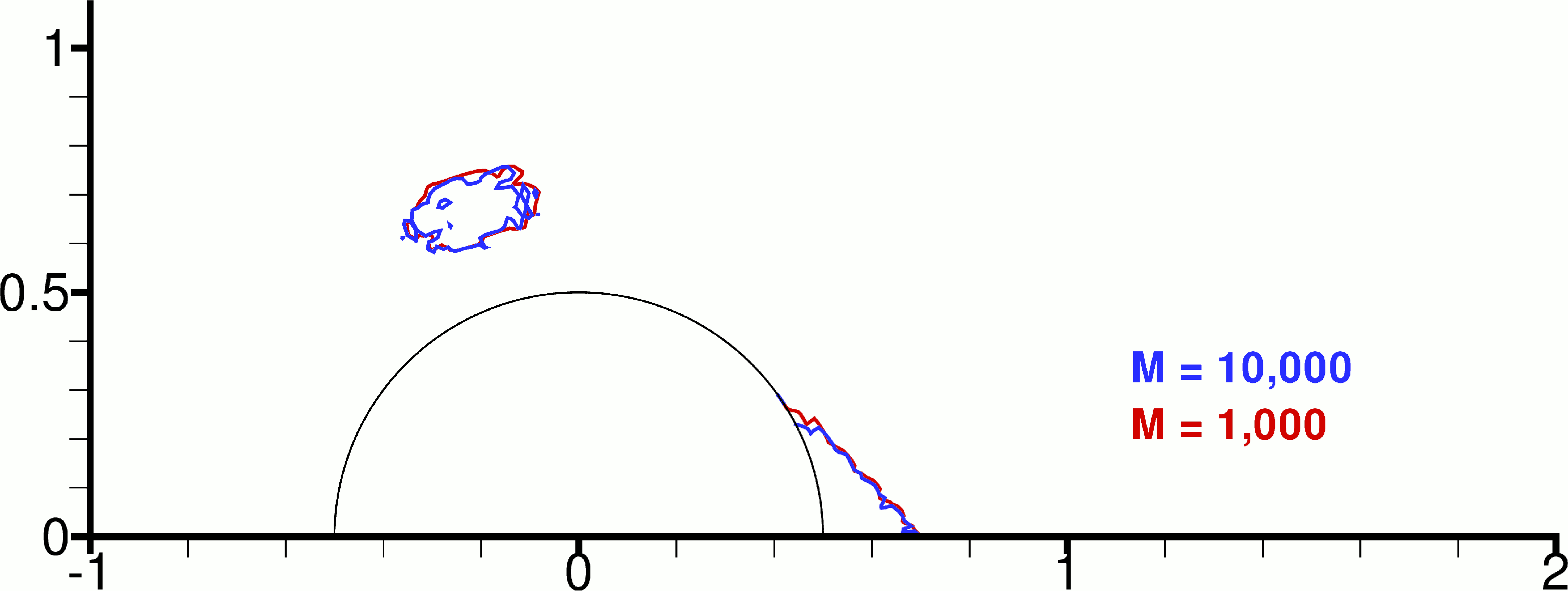
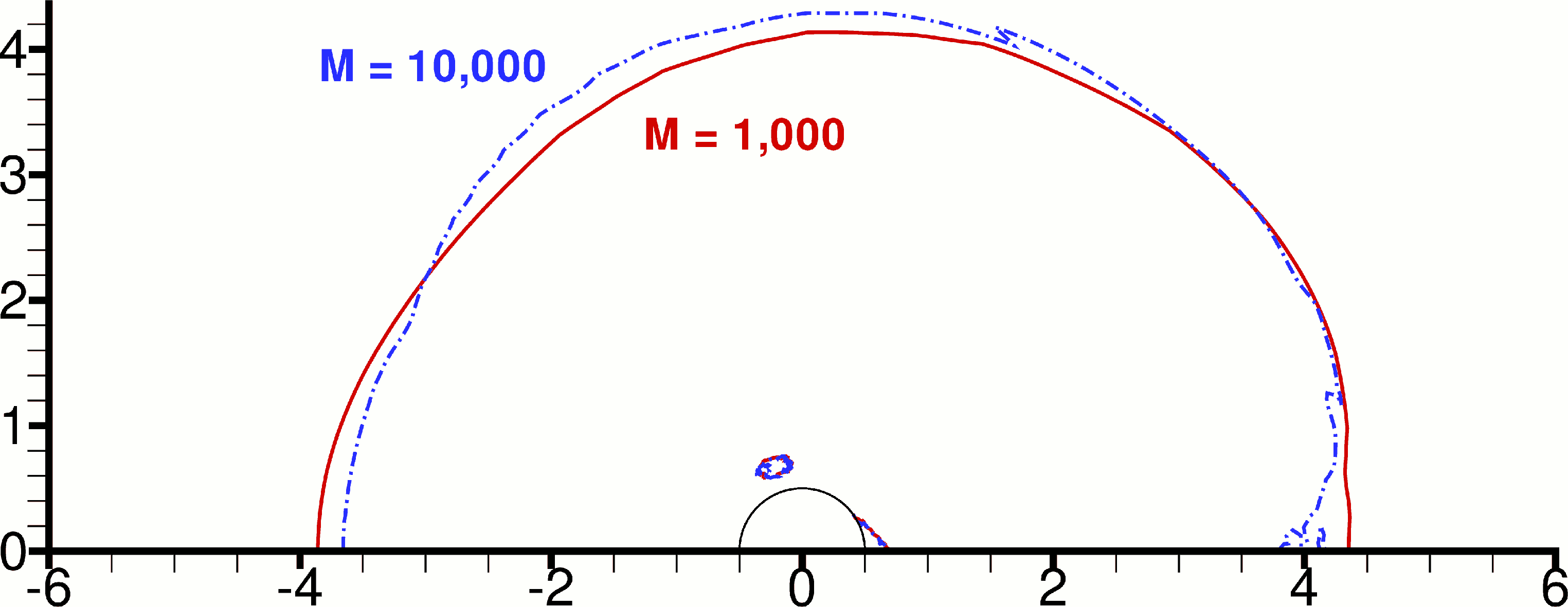
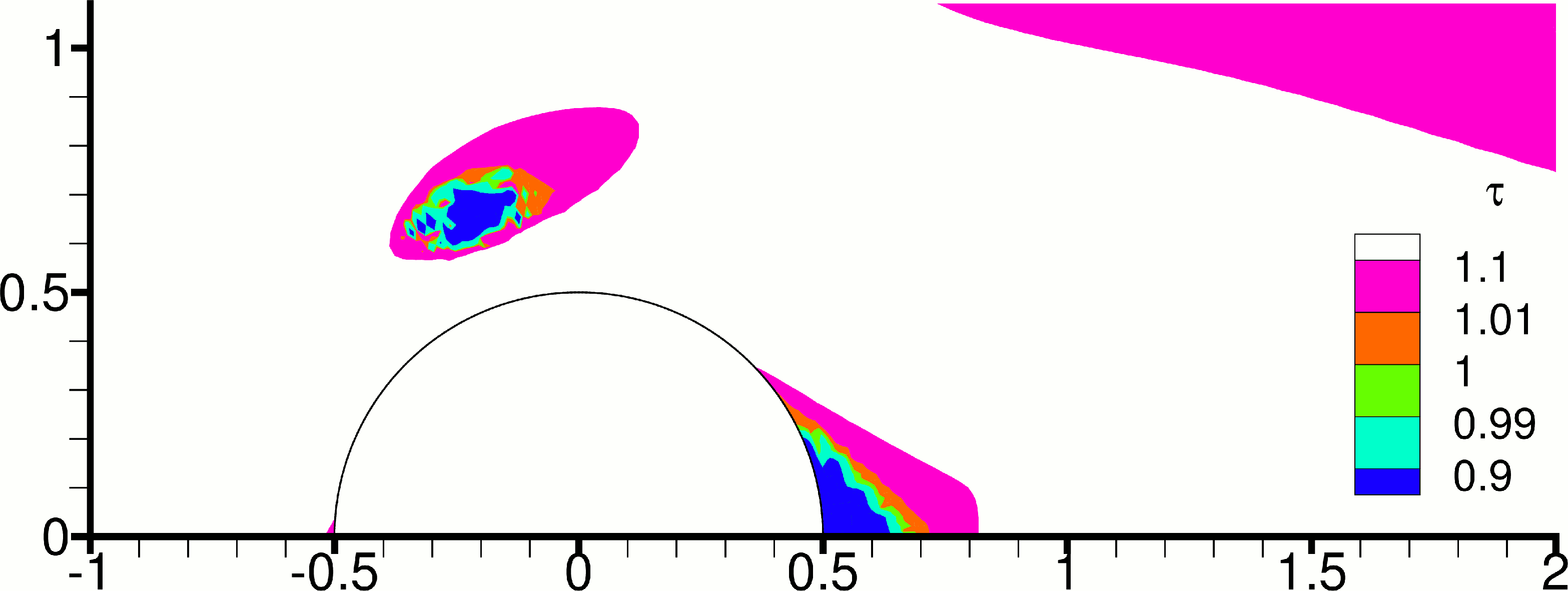
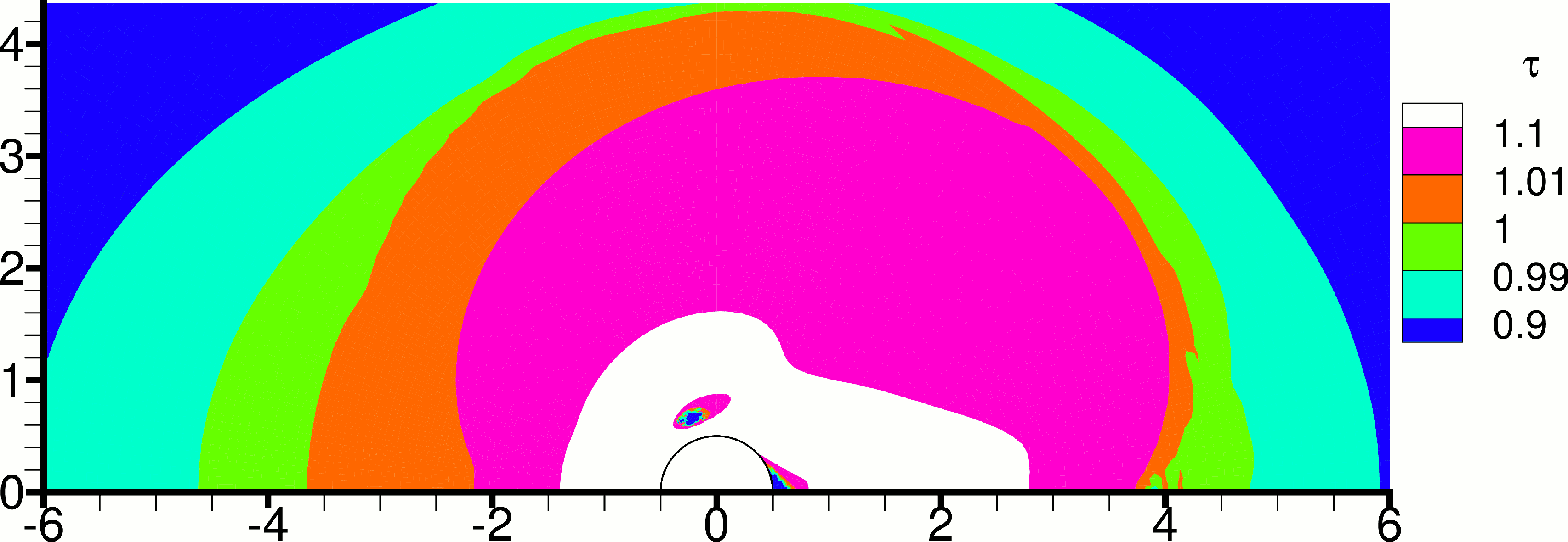
Before proceeding to the presentation of the thixotropic results, it is useful to discuss the choice of the regularisation parameter . Figures 6 and 7 provide a comparison of the results with two different values of this parameter, and , both close to, and far from, the cylinder. Figures 6 and 7 show that, concerning the yield lines, estimated using , both values of produce essentially the same results near the cylinder, the main difference being that the results with are not smooth. This observation, that the predicted yield lines lose their smoothness when is large, has been noted also in other studies (e.g. [32, 33]). On the other hand, Figure 6 shows that, for , the different parameters produce very different yield surfaces far from the cylinder: the yield surface produced with is located much farther away from the cylinder than that produced with . Figure 6 sheds some light into this: it can be seen that between the two yield surfaces (that computed with and that computed with ) the stress field changes by less than one percent. Therefore, if changing to causes a one percent change in the stress field, then this change in the location of the yield line is expected. The problem lies in the very gradual variation of the stress field near the yield stress, which is a problematic situation for predicting the yield surfaces with regularisation methods, as pointed out by Frigaard and Nouar [34]. Close to the cylinder (Fig. 6) the variation of stress is much more rapid and the problem is not manifested. In the case the stress varies relatively rapidly both close to the cylinder (Fig. 7) and far from it (Fig. 7), so the results with and are similar even far from the cylinder (Fig. 7). Another test is performed by comparing the stress magnitude distributions along the cylinder surface in Fig. 8, and also the drag coefficients obtained with the different values of in Table 1. The drag coefficient is defined as
| (19) |
where is the total horizontal force on the cylinder (due to both pressure and shear stress). The force equals twice the value computed for half the cylinder in our half-domain. Table 1 shows that, for , using instead of results in a relative difference of 2.77 % for the drag coefficient, which is small but not negligible. For the relative difference is much smaller, 0.45 %. These observations agree with those of previous studies such as [35, 24], where it was suggested that lower values of can be used with higher values of . See however [36] for a counterexample. In the present study it was decided to use a value of = 1000, because the focus is close to the cylinder, and = 1000 produces smoother results.
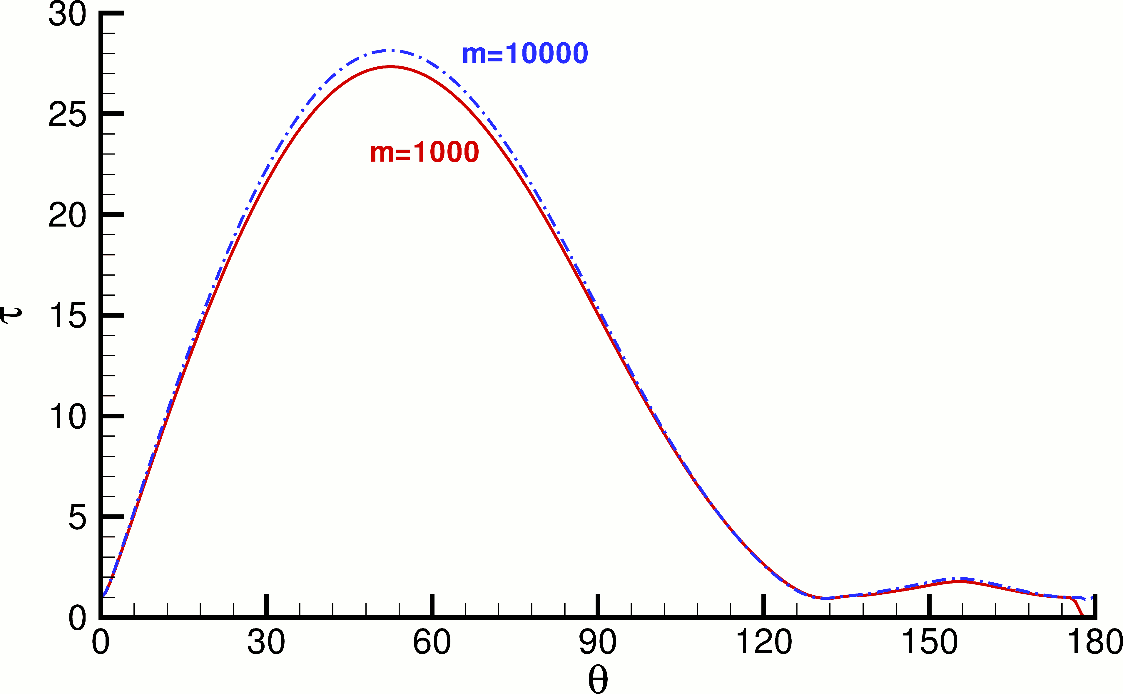
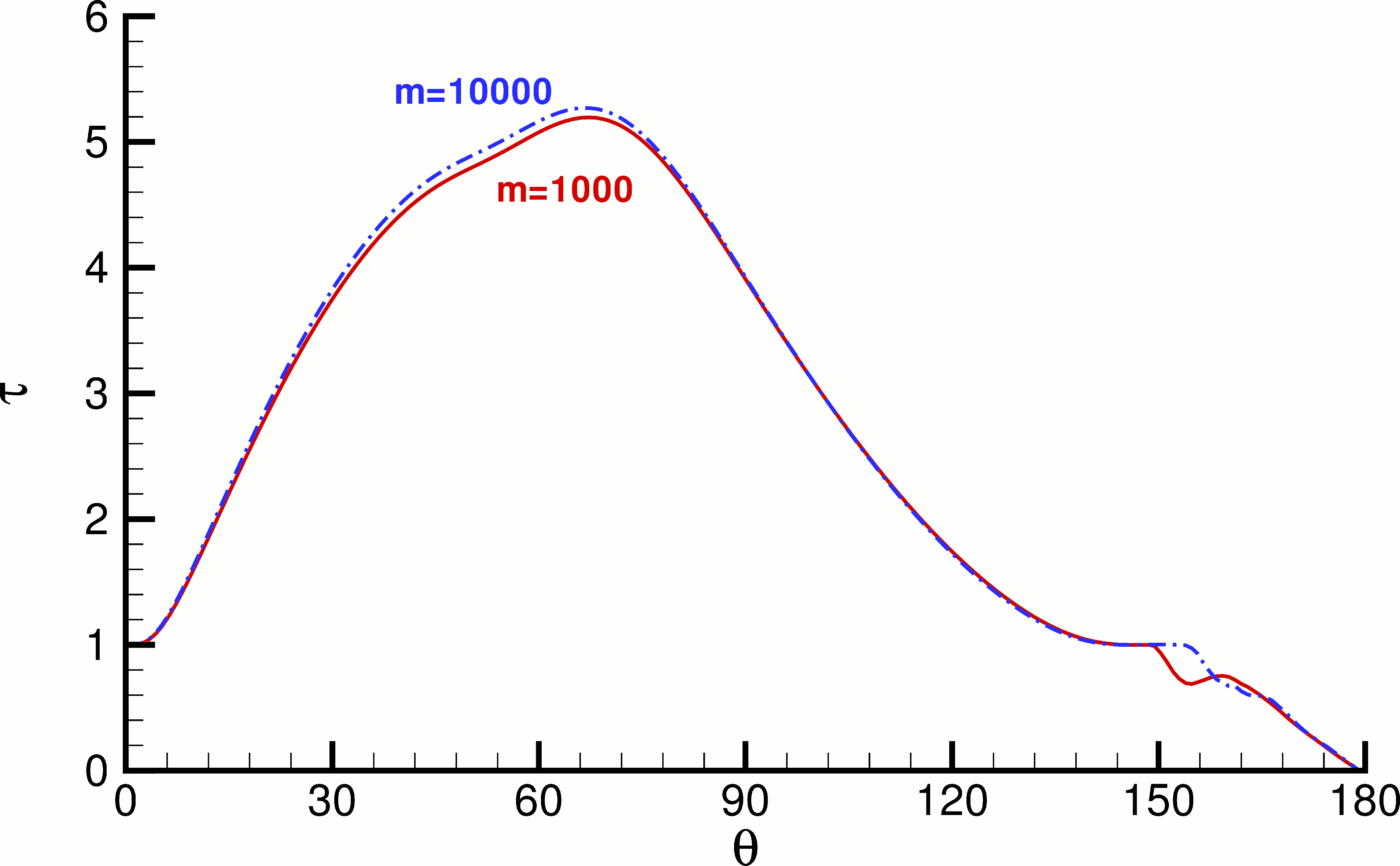
| = 0.5 | = 5 | |
|---|---|---|
| = 1000 | 1.7789 | 4.7947 |
| = 10000 | 1.8296 | 4.8162 |
| difference | 2.77 % | 0.45 % |
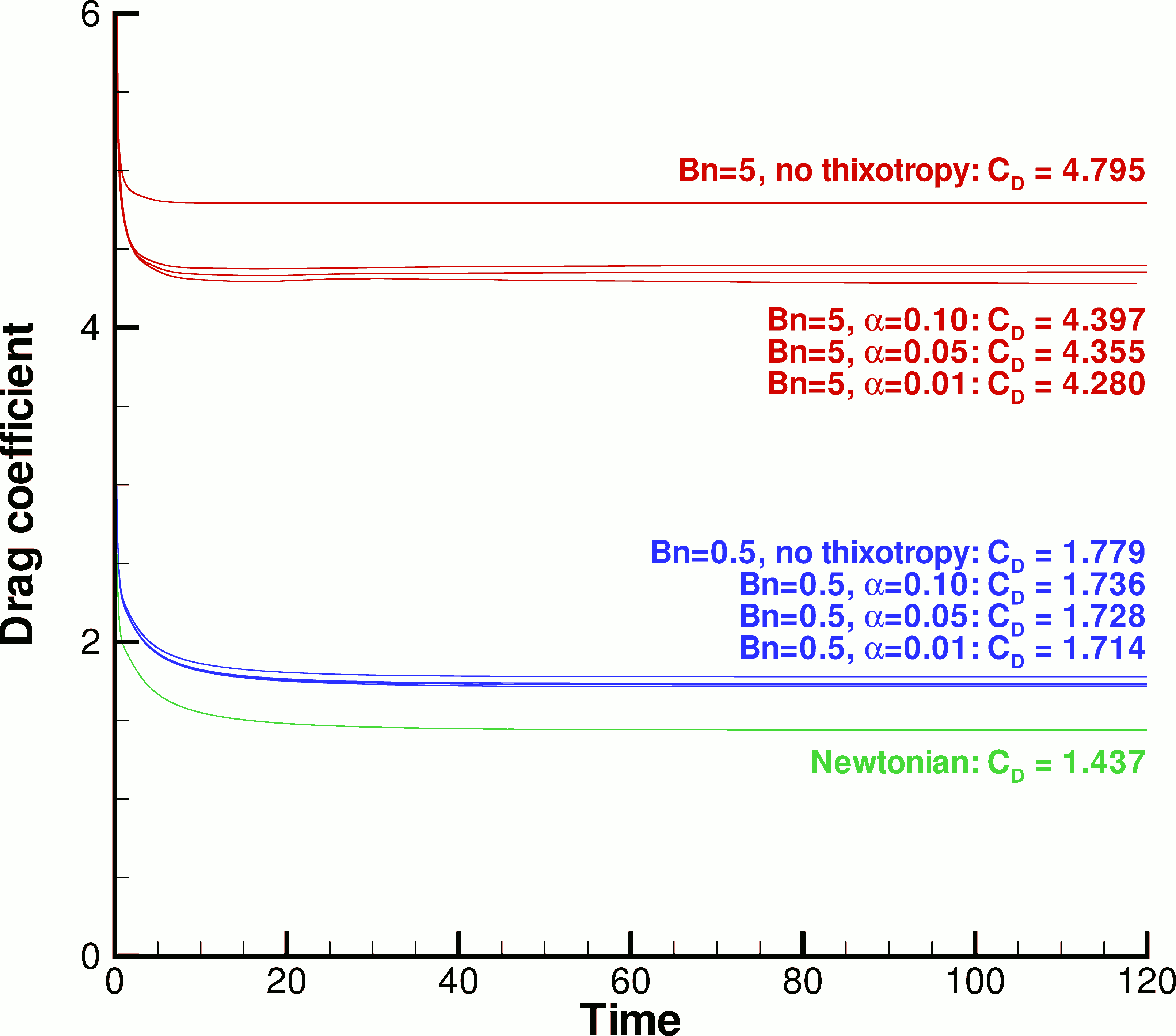
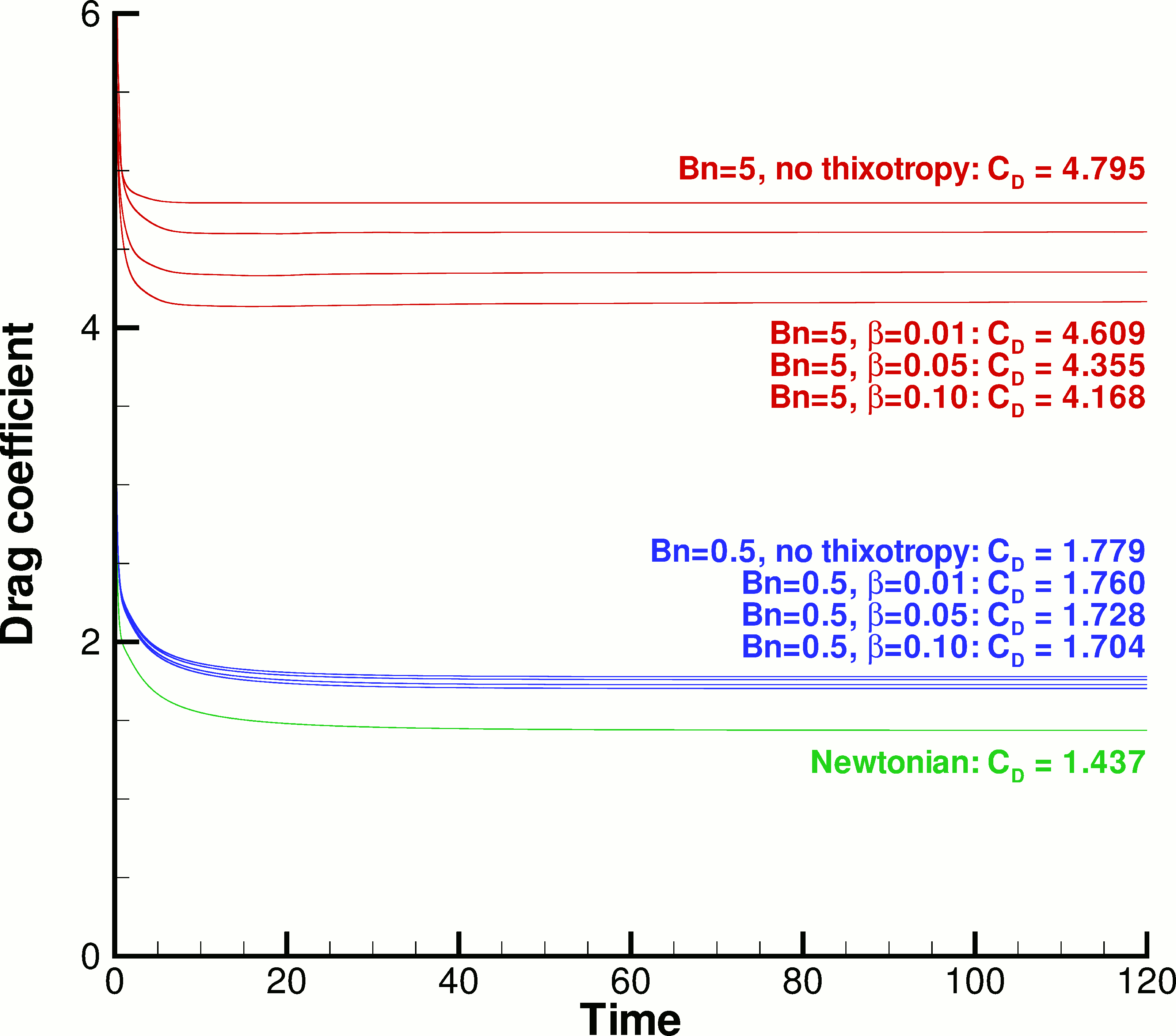
The focus in the present paper is on the steady-state results, but since the problems were solved as transient, we start with a few results concerning the evolution of the flow in time. Figures 9 and 10 show snapshots of the flow fields at times = 1, 5 and 15, for and , respectively. Initially, at = 0, the viscoplastic material is everywhere unyielded, since the zero initial velocity implies also zero rate-of-strain. Setting the fluid to motion suddenly at = 0 creates large rates-of-strain around the cylinder, as can be seen in Fig. 17 (to be discussed later) which shows that the drag coefficient is very large – in fact, as = 0 is approached, the drag coefficient increases way beyond the maximum range = 6 of the -axes of the Figures. This creates a yielded zone around the cylinder, but as time progresses some unyielded zones form again within this yielded zone, and grow up to a maximum size. For = 0.5 (Fig. 9), as time progresses a recirculation zone grows behind the cylinder, and at = 5 it seems to have already reached its maximum size. For = 5 (Fig. 10) the low-shear region that develops behind the cylinder results in an unyielded zone instead of a recirculation zone. Structure breakdown starts on the cylinder surface, especially at the upstream part where the rate of shear is highest. Comparison against Figures 11(c), 11(d), 13(c) and 13(d) (which correspond to = 120) shows that at = 25 the steady state has been nearly reached.
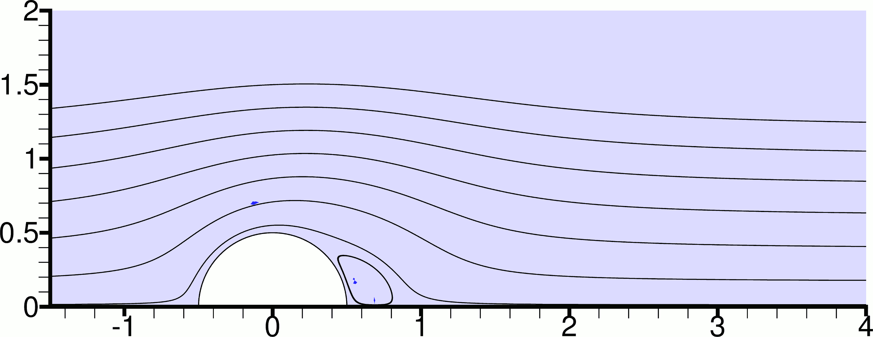
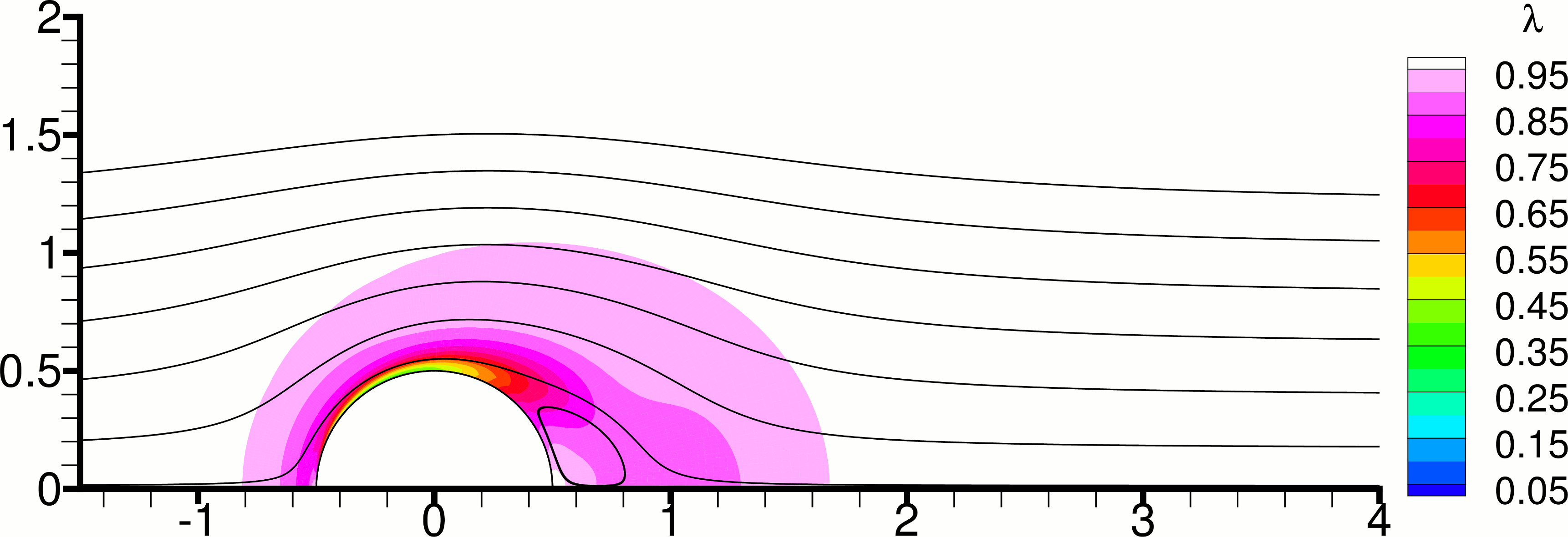
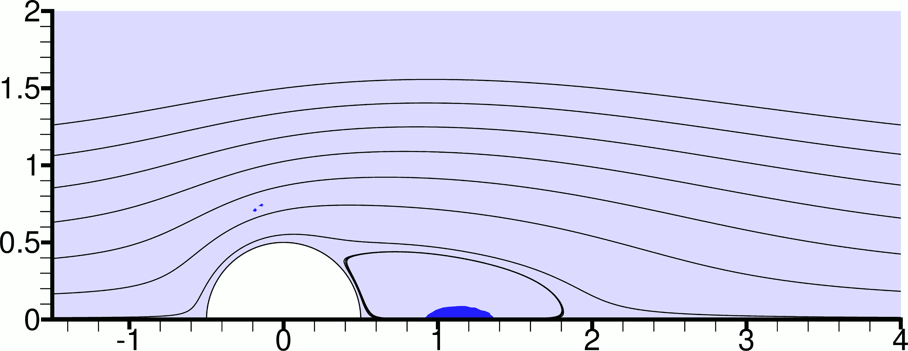
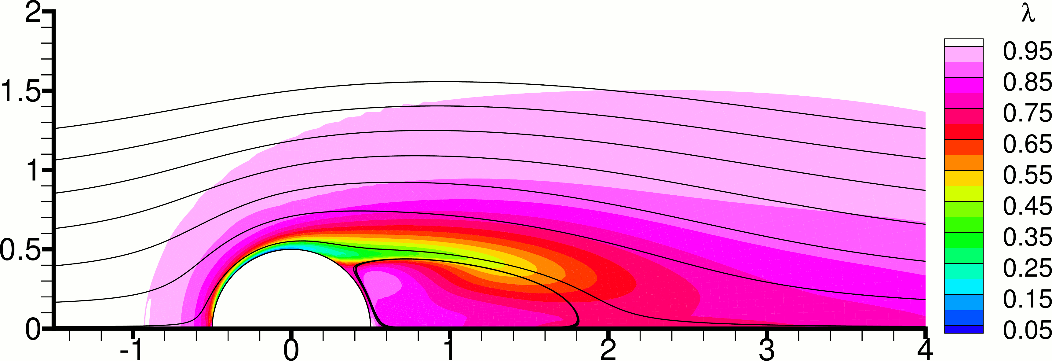
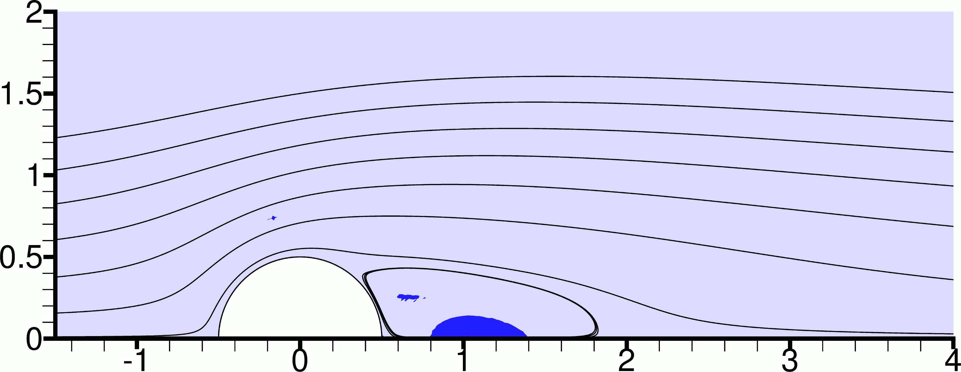
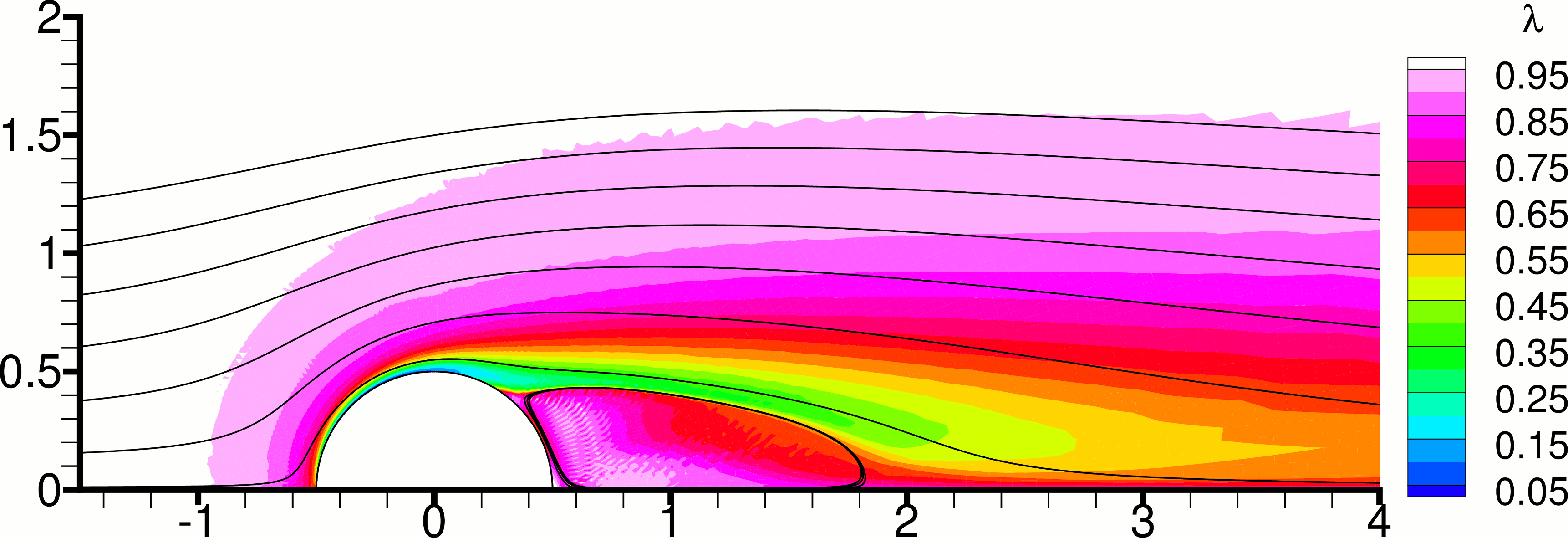
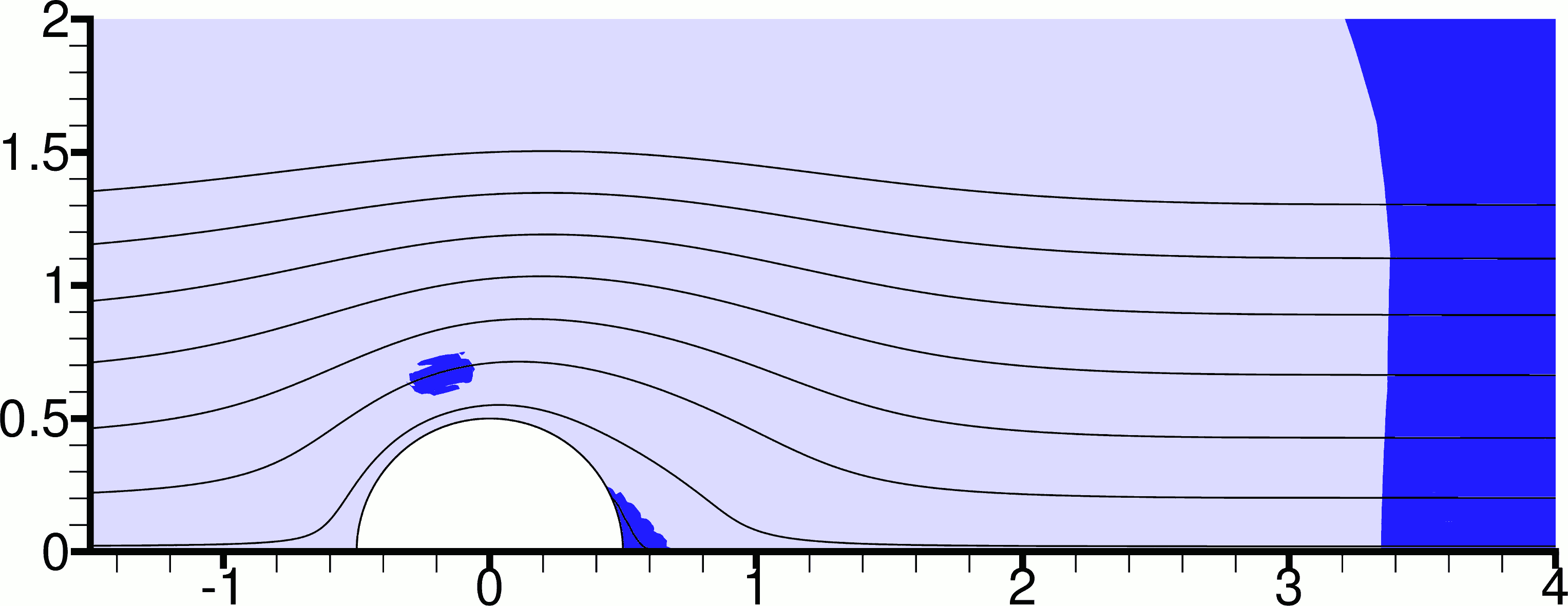
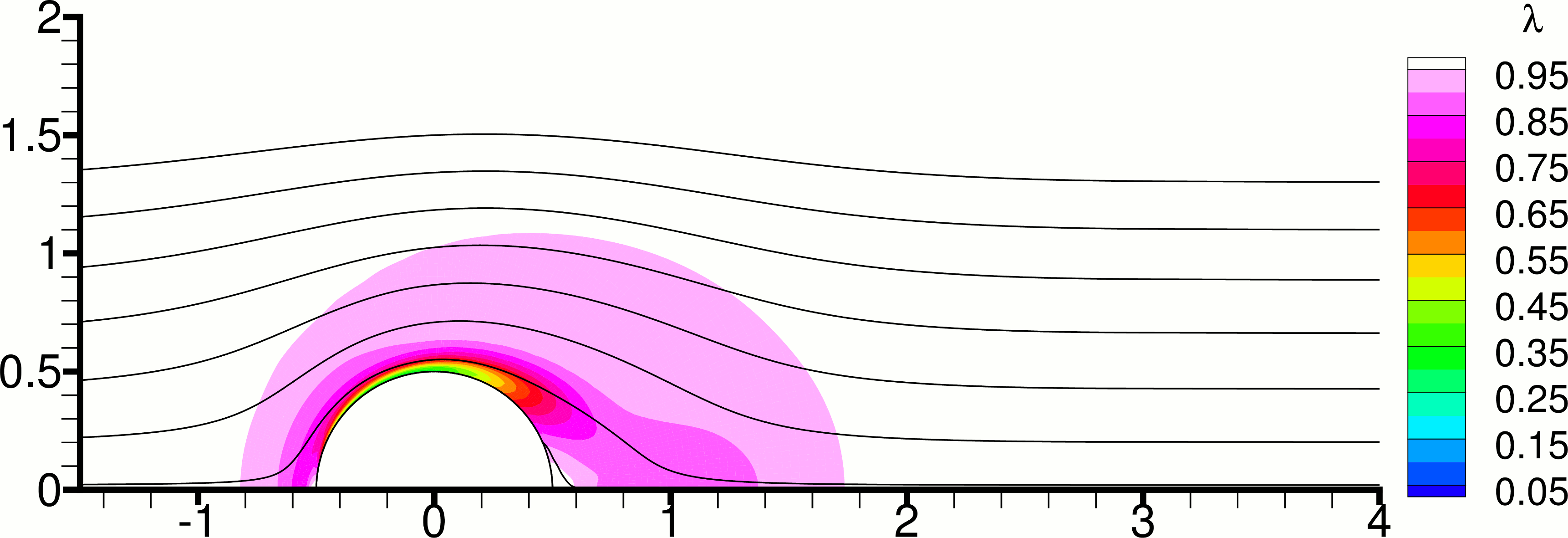
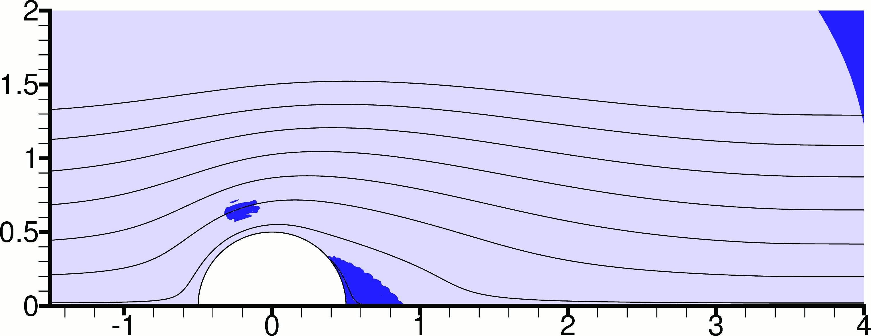
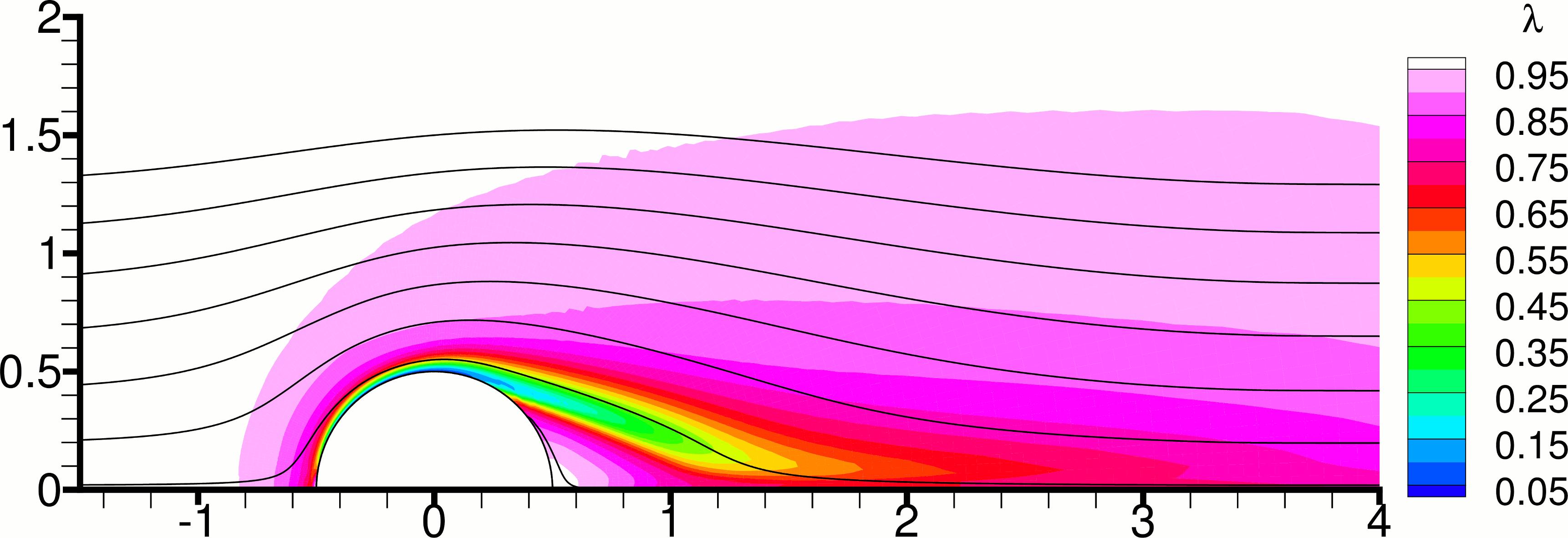
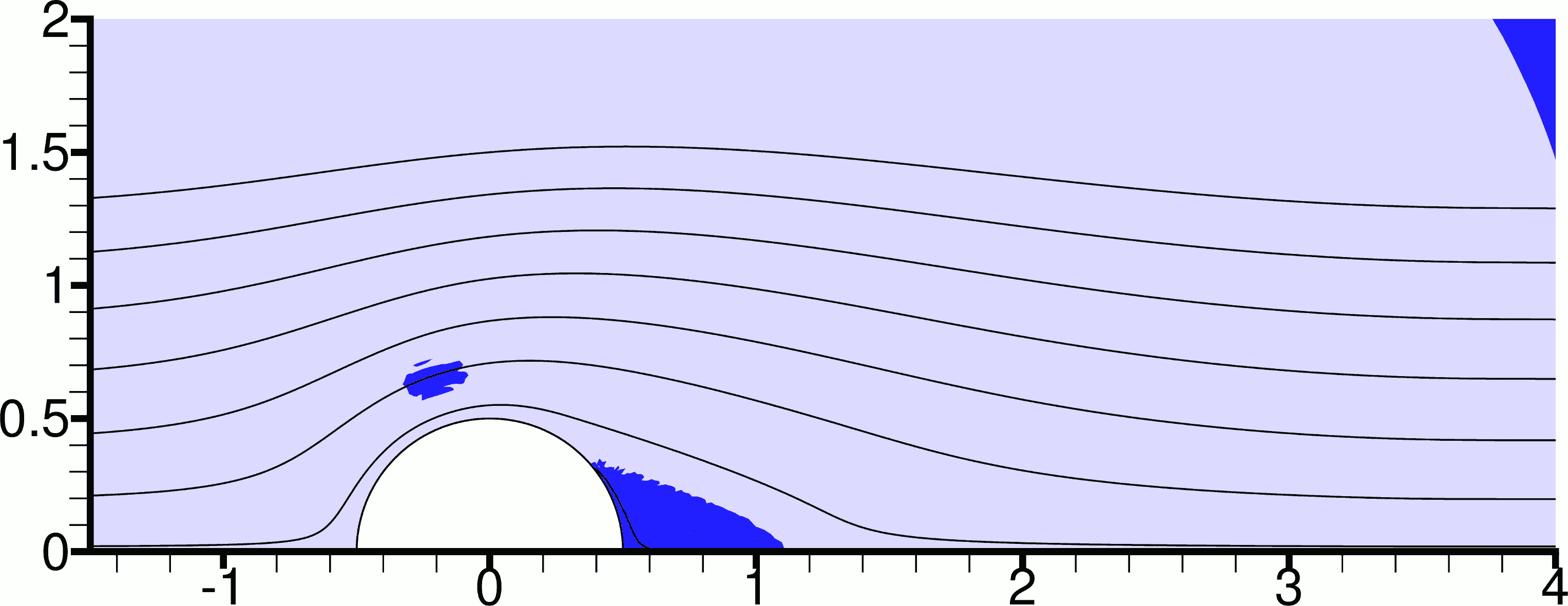
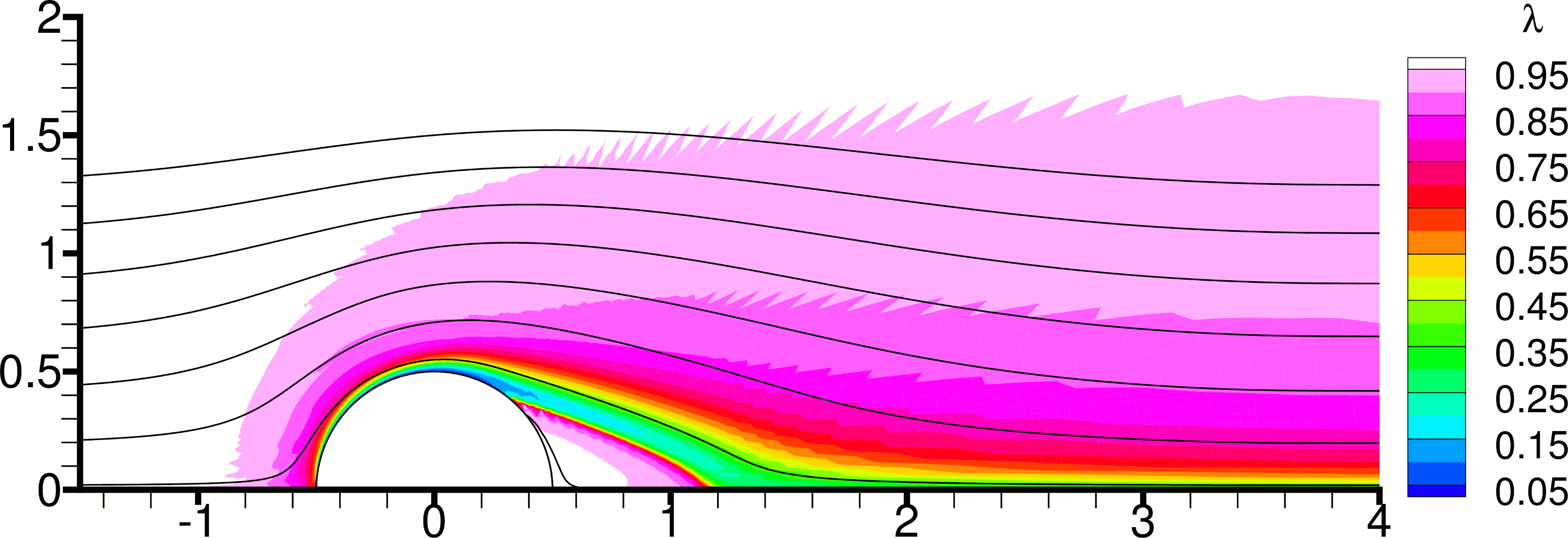
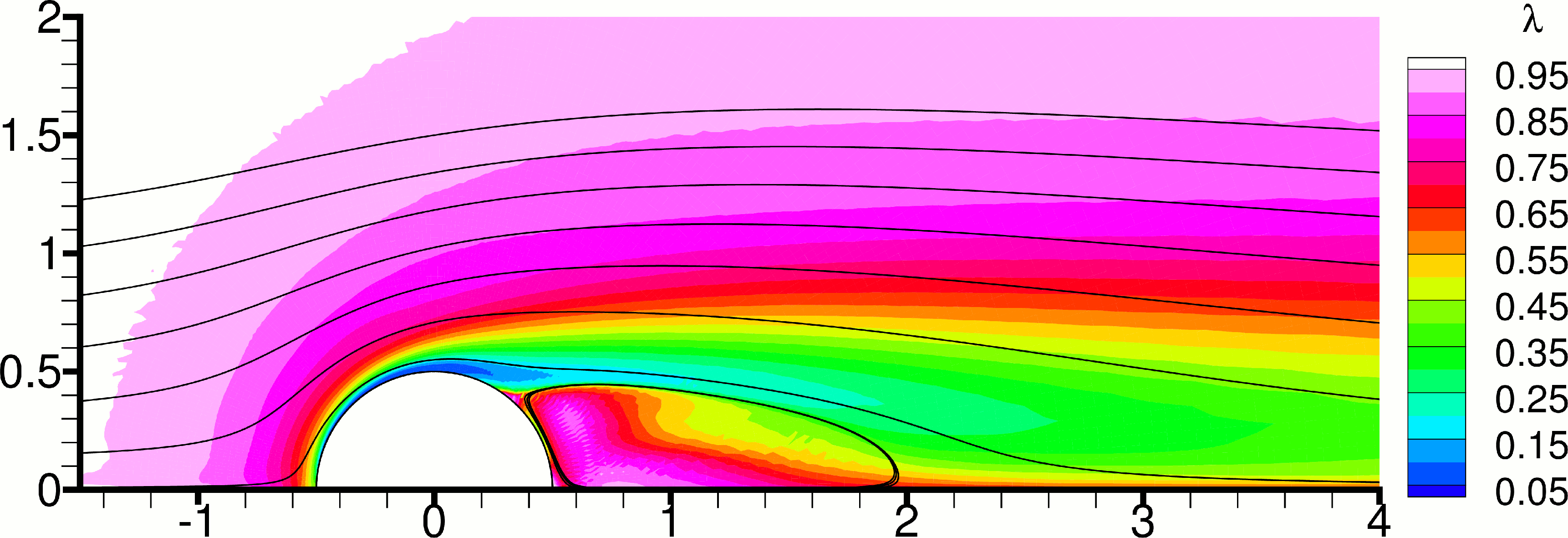
Next we discuss the steady-state results. Figure 11 shows the effect of varying the thixotropy parameter , with and fixed at . As expected, increasing the value of causes the flow to become more viscous, with a corresponding reduction in the length of the recirculation bubble. Increasing from 0.01 (Fig. 11(a)) to 0.05 (Fig. 11(c)) leads to an increase in the size of the unyielded zones, and their movement closer to the cylinder. A further increase of to 0.10 (Fig. 11(e)) moves the unyielded zones yet closer to the cylinder, but rather reduces the size of the largest zone. These effects are analogous to increasing the Bingham number, or decreasing the Reynolds number, as can be seen from Figure 3. Concerning the state of the structure, it can be seen in Figure 11 that, as one would expect, it is mostly broken down in the thin boundary layer on the cylinder surface upstream of the separation point, and in the following thicker shear layer between the recirculation bubble and the main flow, where can reach values as low as 0.1 (Fig. 11(b)). It is interesting to observe that inside the recirculation bubble the structure is broken when is small (Fig. 11(b)) but it is nearly fully developed when is relatively large (Fig. 11(f)). This can be attributed to the faster structure recovery in combination with the lowering of the shear rates in the recirculation zone due to the more viscous character (higher stresses) when is large.
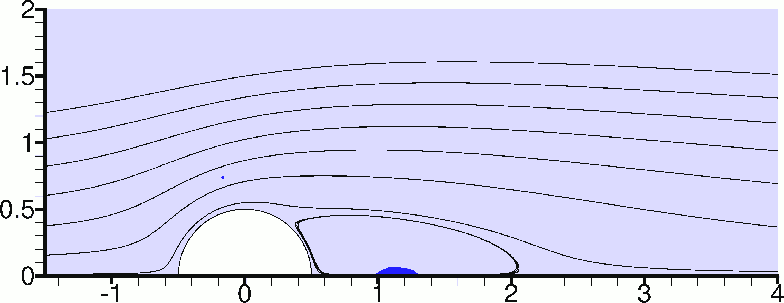
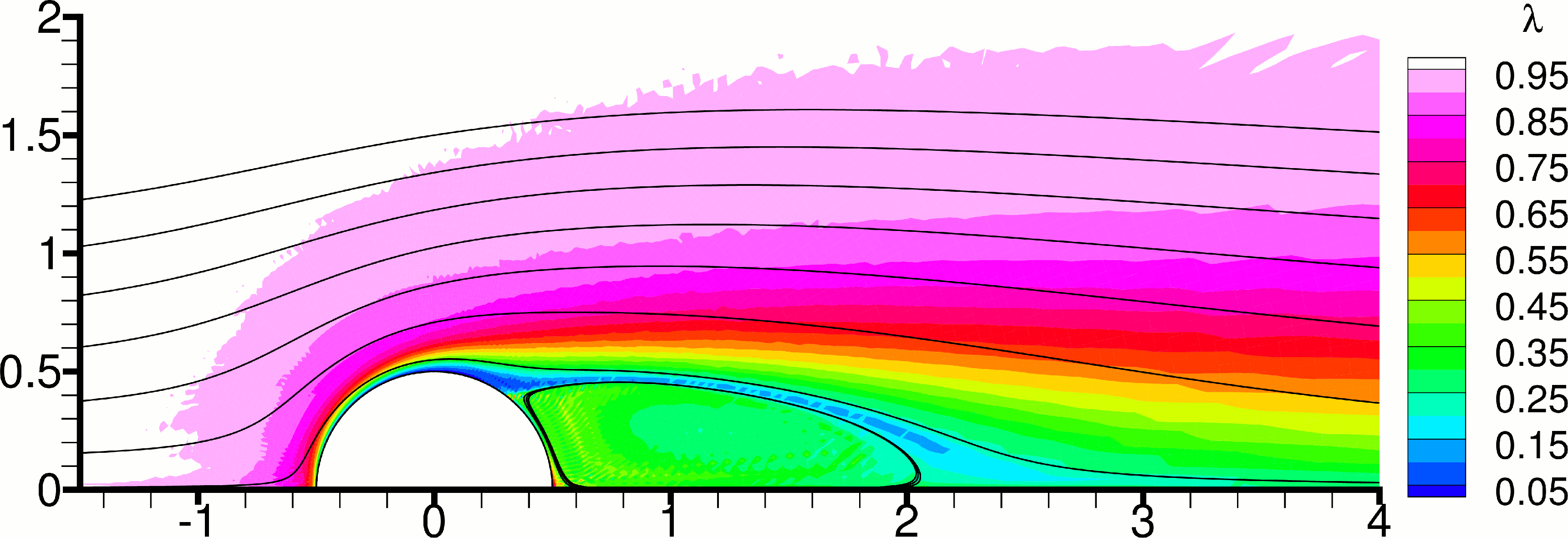
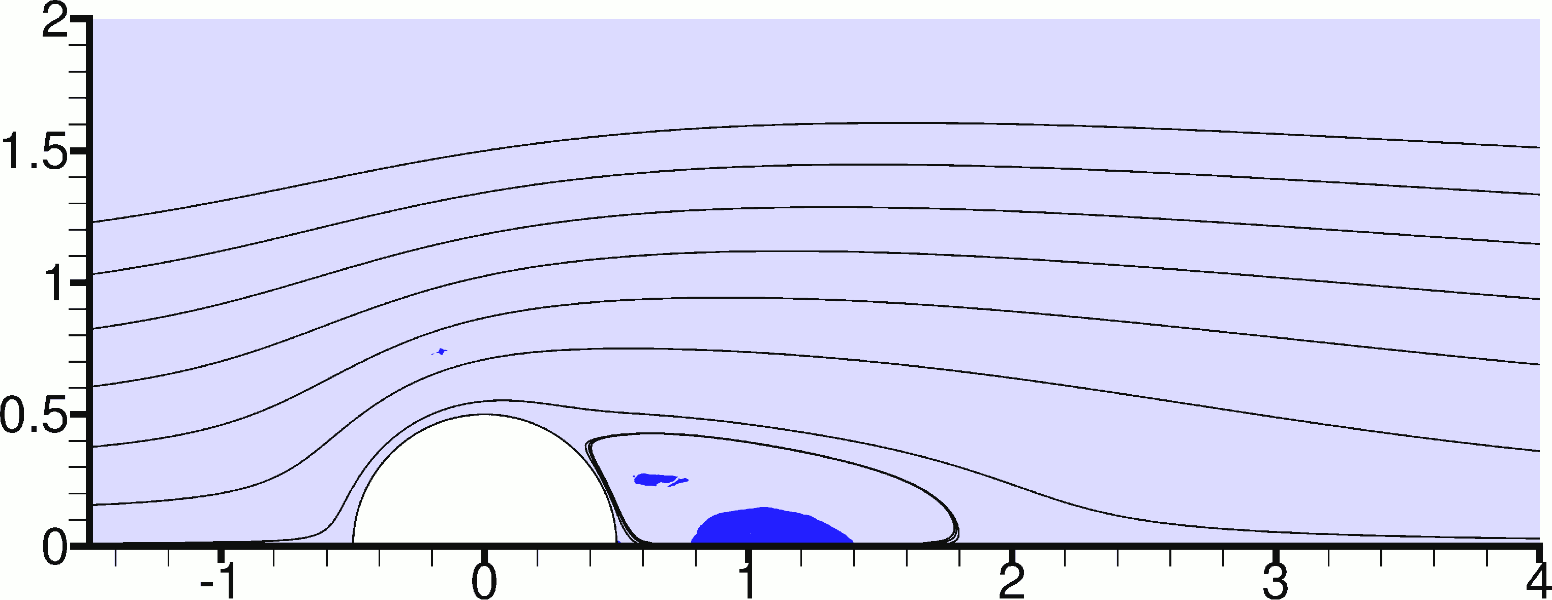
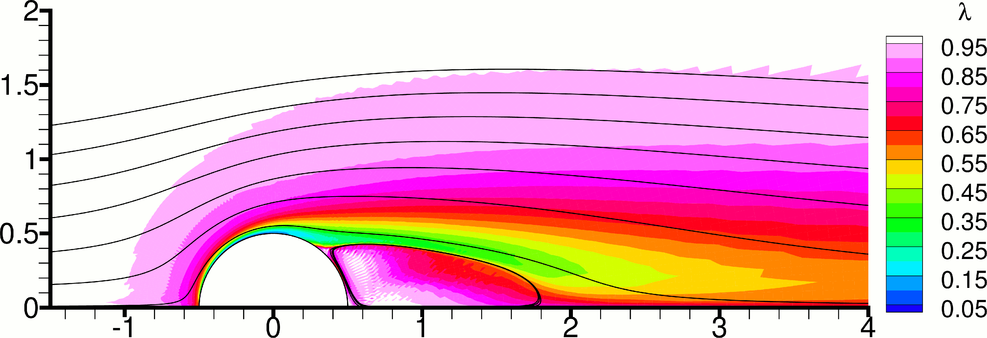
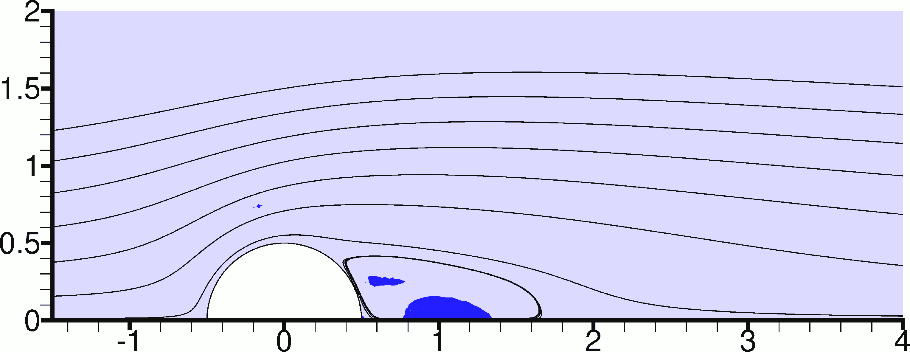
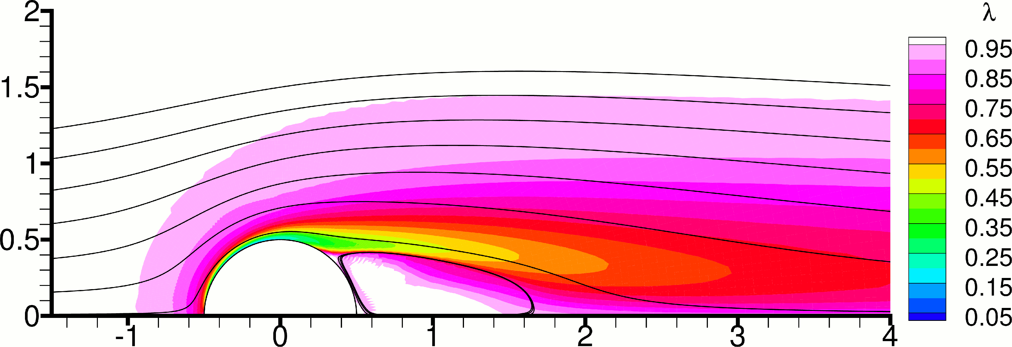
The opposite effects are caused by increasing the value of , as Figure 12 shows. It is worth noting that within the selected range of values, the parameter appears to have a stronger influence on the field compared to the parameter , except within the recirculation bubble. As will be discussed below, structure breakdown is the dominant mechanism near the cylinder, because it is there that boundary layers and high shear rates develop leading to high breakdown, whereas the rate of structure recovery is too slow to produce significant changes during the time that it takes for a fluid particle to flow over the cylinder. The particle is then carried away and the effect of structure recovery becomes more manifest downstream, away from the cylinder. An exception to this is the fluid inside the recirculation zone, which is trapped in there and so the effect of recovery accumulates there. This makes the state of the structure inside the recirculation zone sensitive to the value of , as can be seen in Fig. 11.
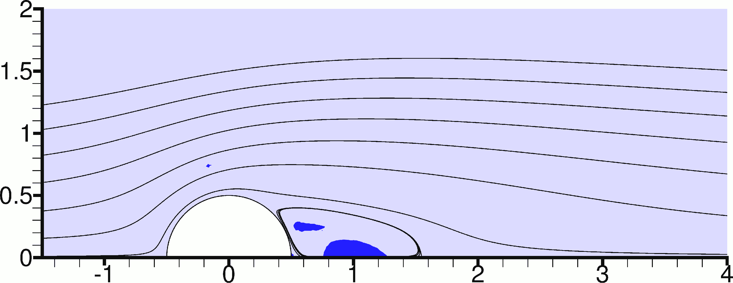
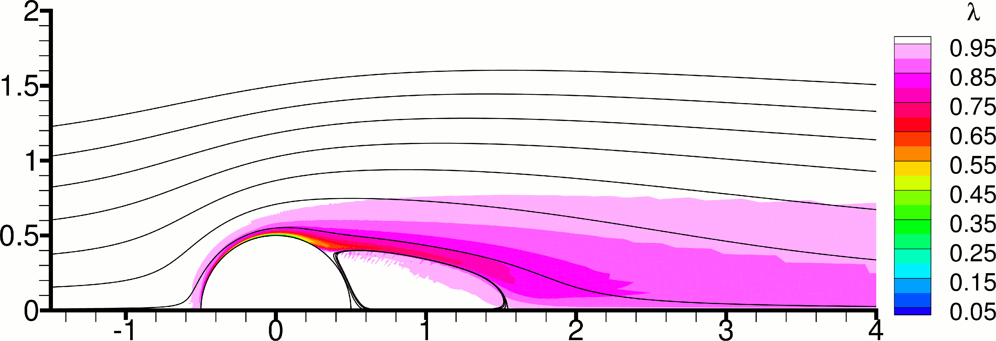


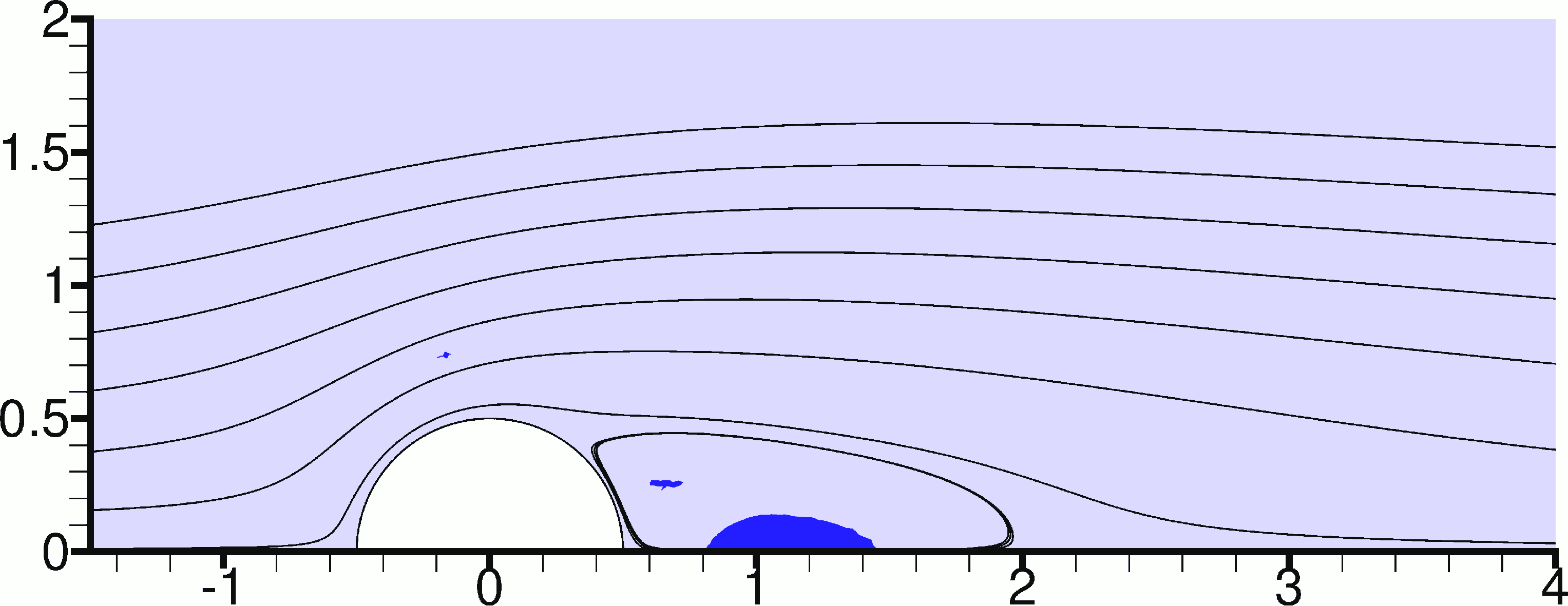
Figures 13 and 14 show the corresponding results for = 5. In this case there are no separation bubbles, and a single large unyielded zone appears attached to the back of the cylinder. The effect of on the size of this zone is difficult to describe, whereas increasing clearly makes this zone larger. In general it could be argued that the size of this zone is determined by two opposing mechanisms: a) Increasing the viscous character of the flow by increasing or , or decreasing or , reduces the velocity gradients in the flow field and causes more fluid to become unyielded, thus increasing the size of the unyielded zones, especially when these zones are detached from the back of the cylinder. b) On the other hand, there appears to exist another mechanism which concerns specifically the unyielded zones that are attached to the back of the cylinder: these zones fill the space that would normally form a recirculation bubble in Newtonian flow. In such a bubble the rates of strain are low, and so when the material is viscoplastic the recirculation bubbles may become unyielded zones. Increasing the viscous character in the Newtonian case moves the separation point further downstream and reduces the size of the recirculation bubble. In the viscoplastic case it shrinks the size of these unyielded zones. The balance between these two mechanisms determines the actual size. Comparison of the present results against those of the creeping flow studies mentioned in Section 1, shows that the size of the unyielded zone behind the cylinder becomes minimum when = 0.
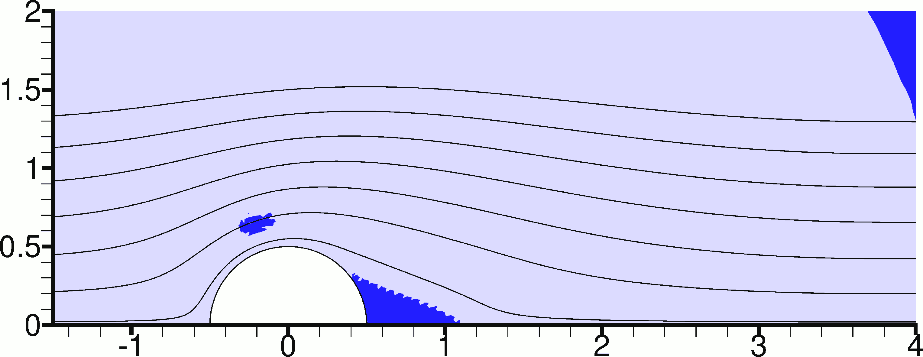
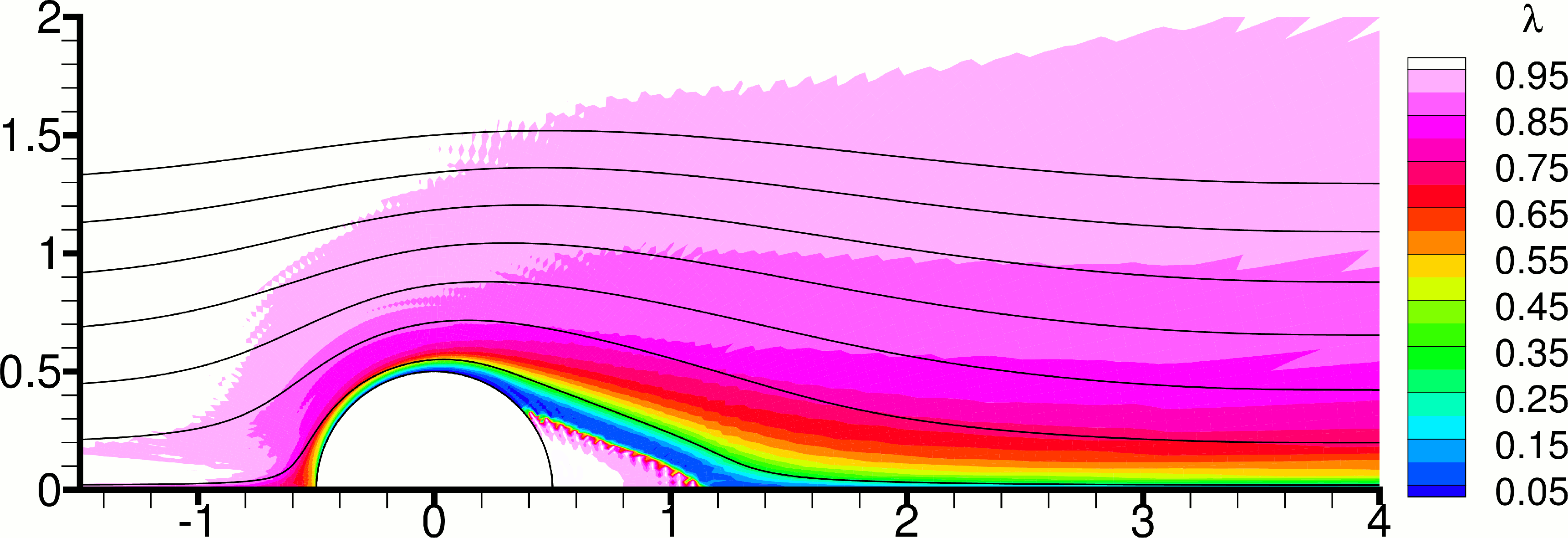
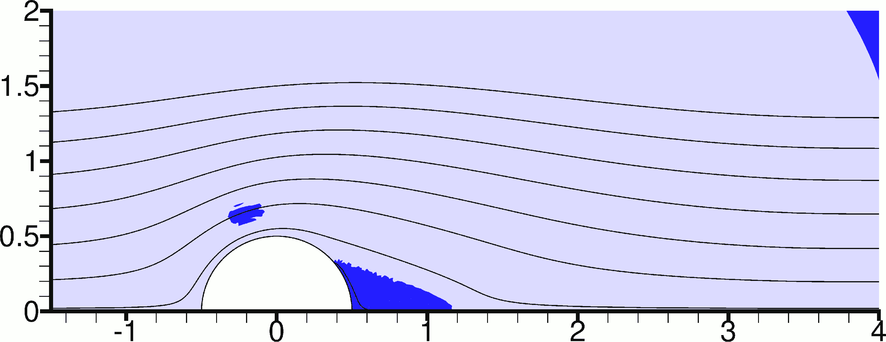
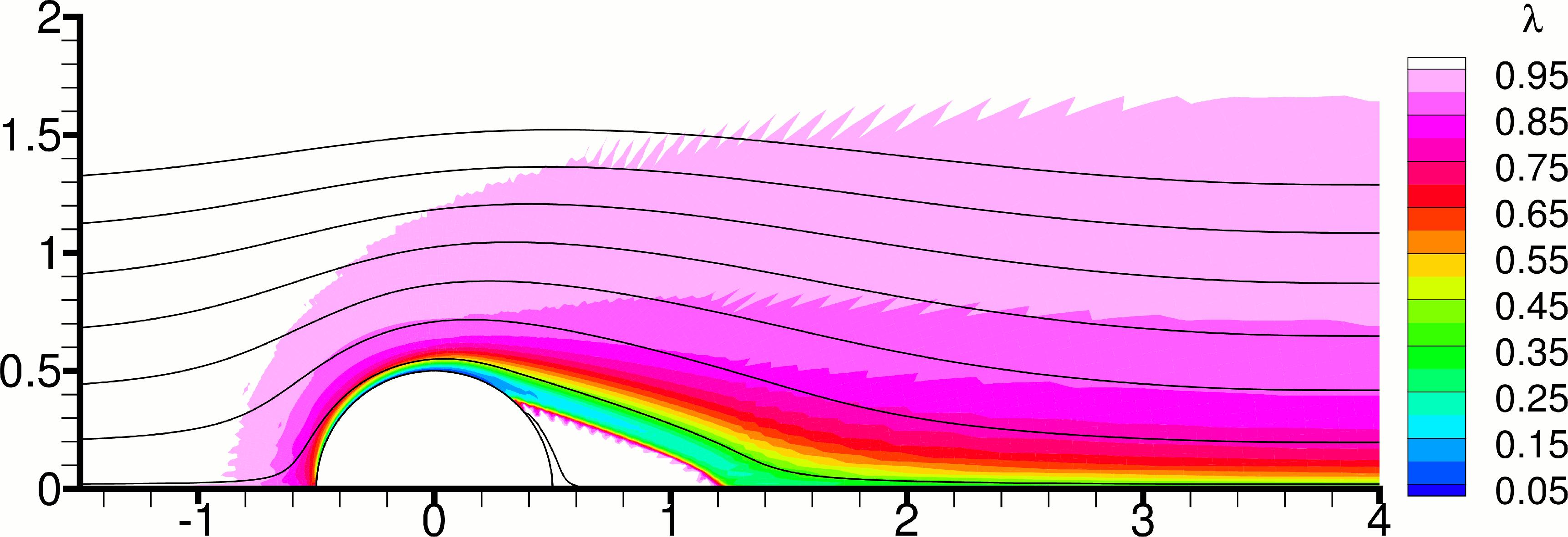
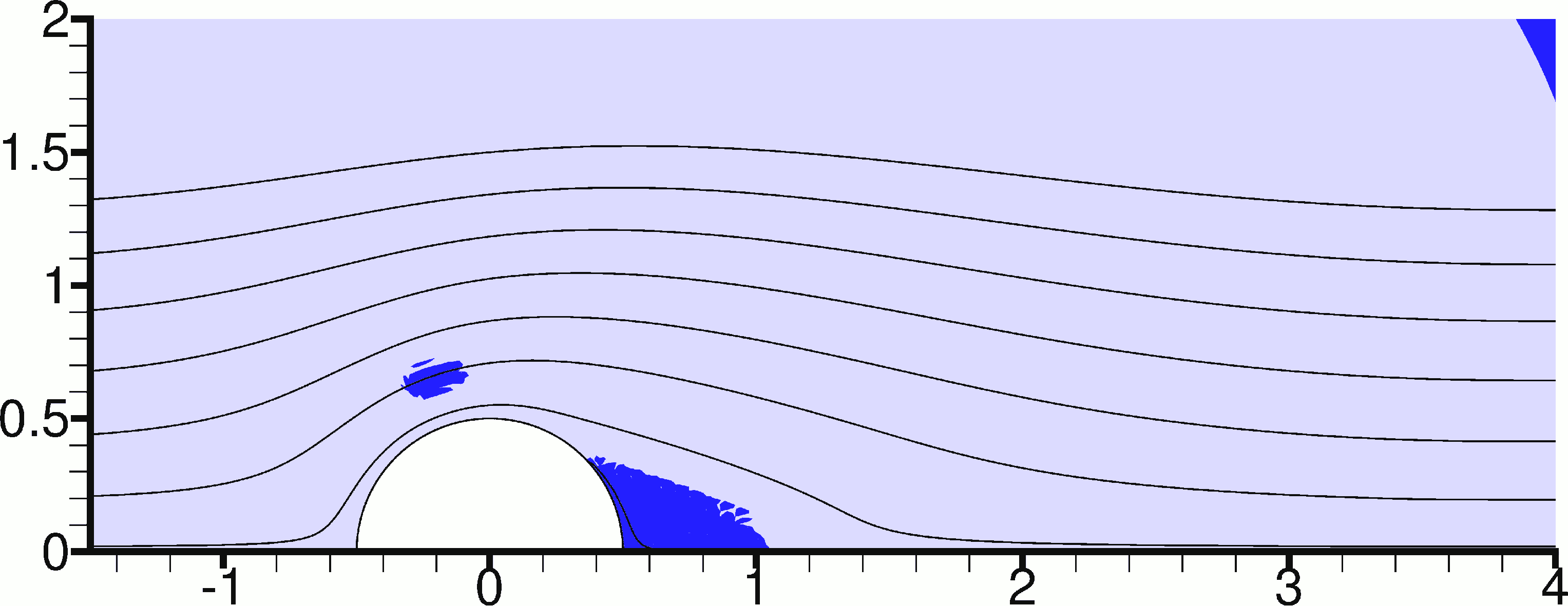
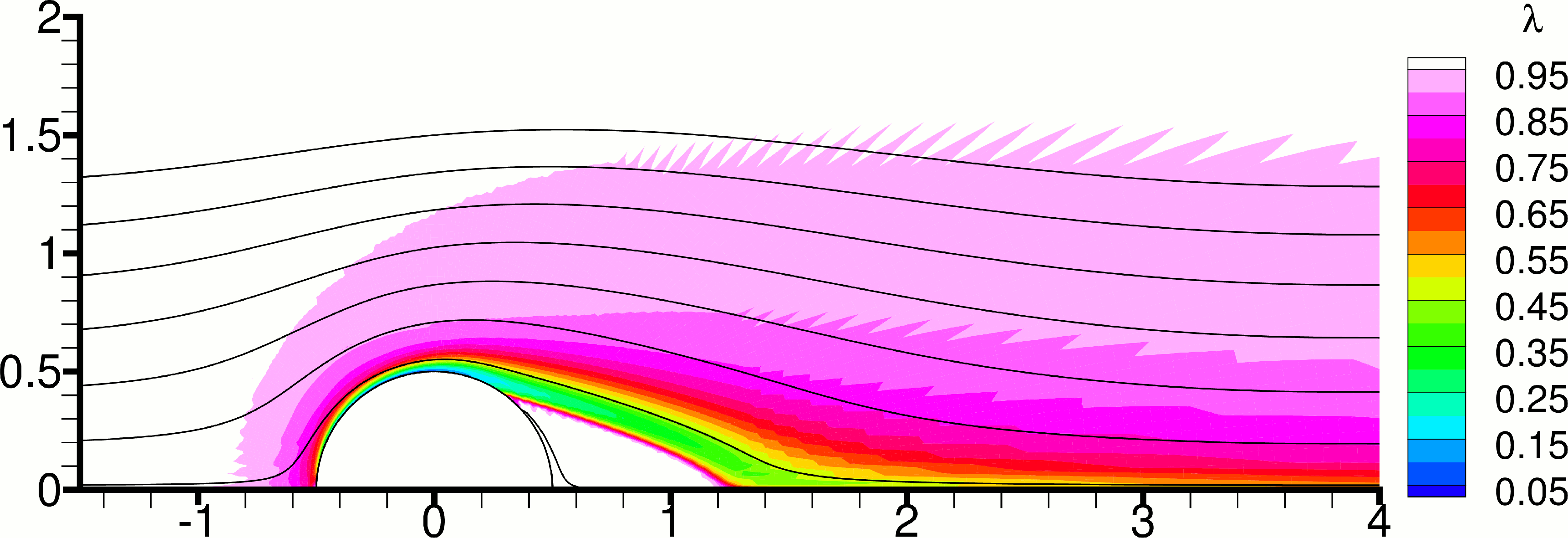
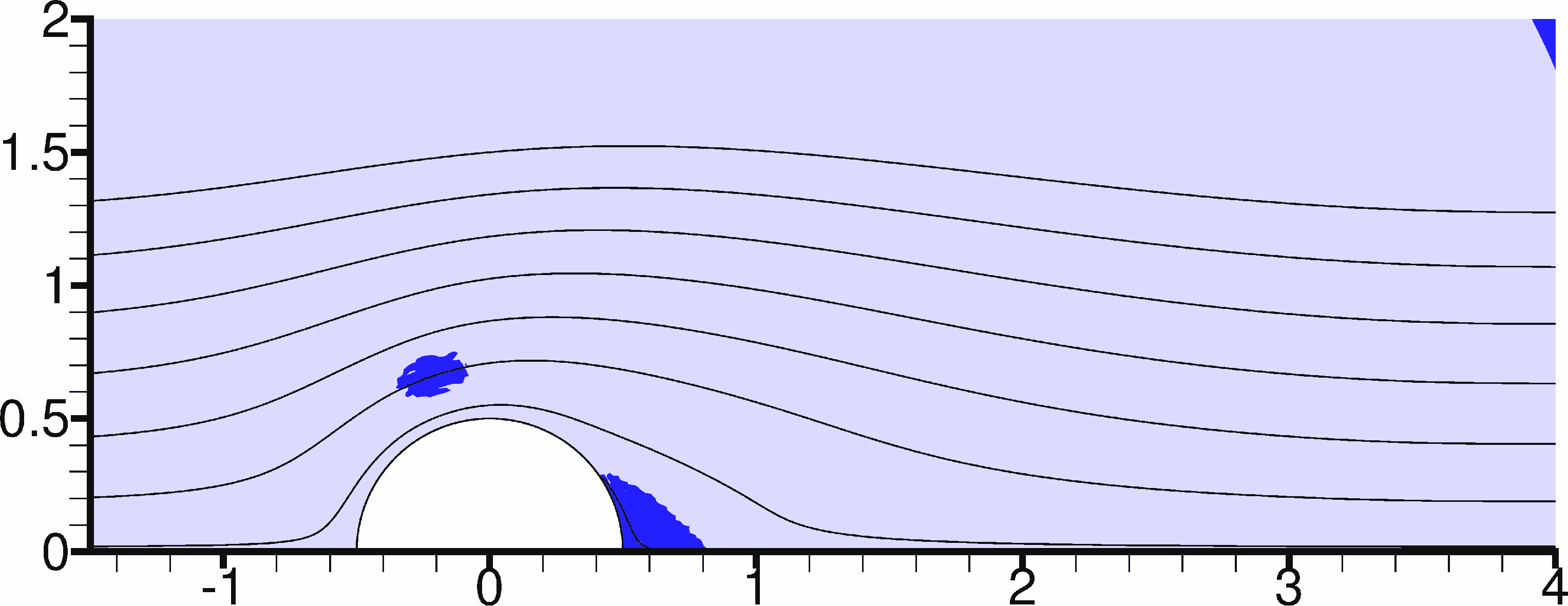
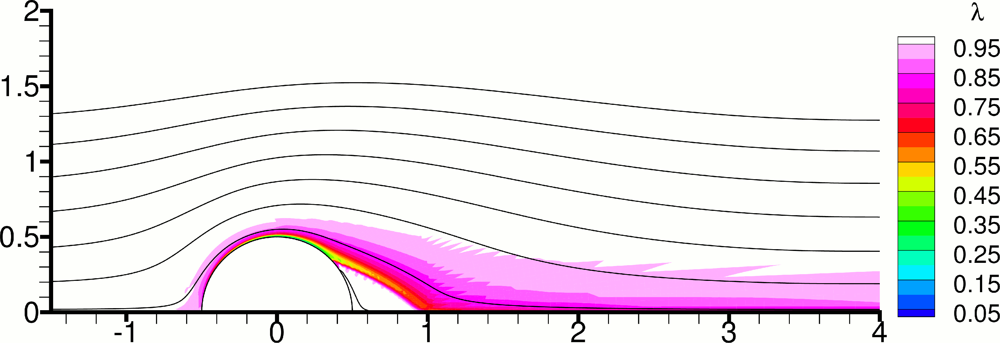


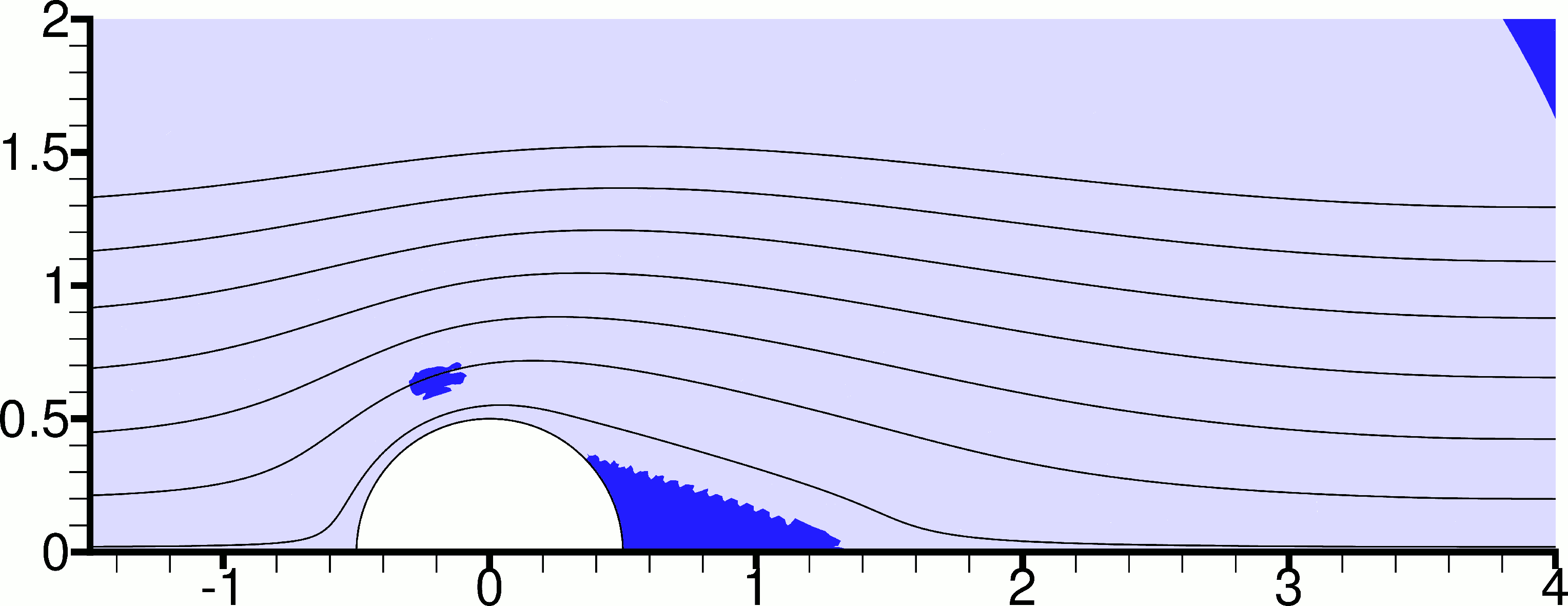
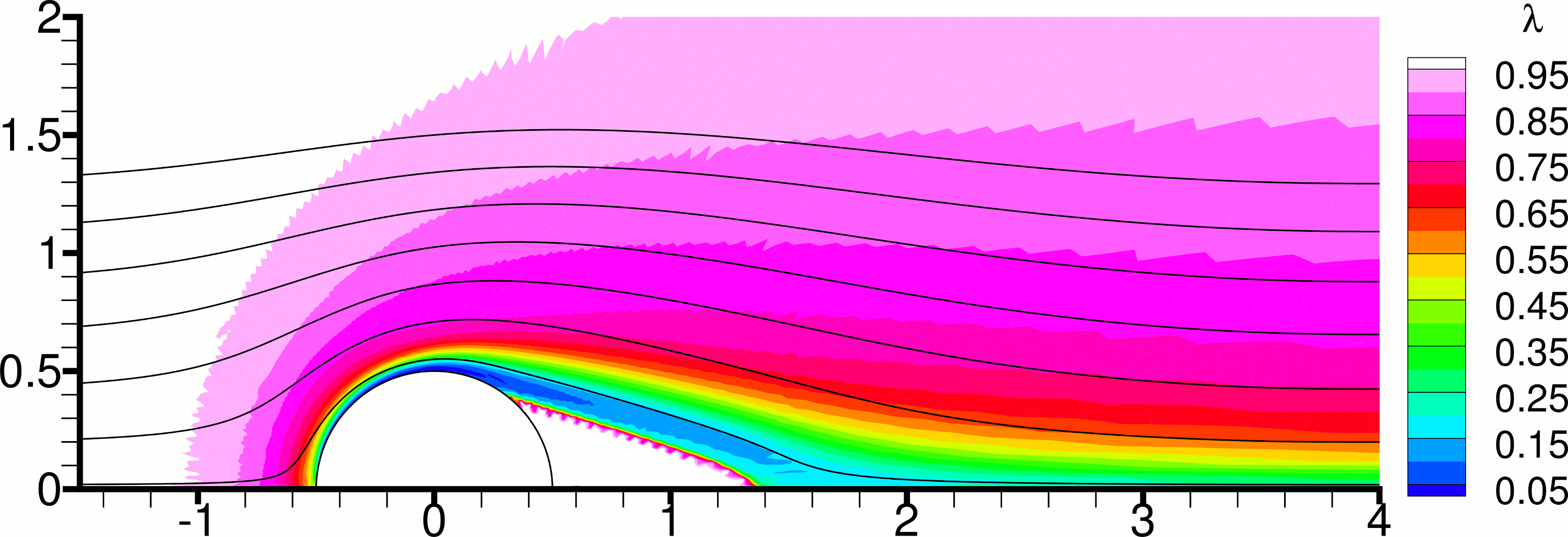
The unyielded zone that is attached to the back of the cylinder in the cases deserves some more attention. It consists of material which is motionless compared to the cylinder, due to the no-slip condition. Therefore this zone acts as a solid extension to the cylinder, and the flow past it should more appropriately be considered to be a boundary layer – an extension of the boundary layer over the cylinder – rather than a shear layer. In this boundary layer, due to the high shear rates, the structure breaks down with values of as low as (Figs. 13(b) and 14(f)). If one moves from the boundary layer into the adjacent unyielded zone, the value of jumps discontinuously from a low value (e.g. ) to . The fact that the transport equation of , Eq. (6), has no diffusion terms allows the existence of such discontinuities across the characteristic lines (streamlines) of the flow field. It is not difficult to explain why throughout this unyielded zone. Since the velocity is zero, no fluid enters or leaves the zone. The fluid contained in the zone is therefore trapped in there, and the structure continually recovers (since there is no breakdown, as the rate of strain is zero in an unyielded zone) until the steady-state value is reached (the fact that in Fig. 13(b) there appears a region where inside the unyielded zone suggests that the steady-state has not been completely reached).
The situation is different with unyielded zones such as that above and slightly upstream of the cylinder for , or the zones behind the cylinder for , which do not leave a mark on the field. The difference is that such zones are detached from the cylinder, and the velocity is not zero on their boundaries. Therefore, fluid flows in and out of the zones. As a fluid particle enters such a zone, it “solidifies” and moves together with its neighbouring particles as a solid body, during which time its structure recovers at the same rate as for any unyielded zone, determined only by (Eq. (12)). However, contrary to zones which are attached to the cylinder, after a finite time the particle exits the zone, it yields, and structure breakdown commences again. There is not enough time for the structure to fully recover as the particle travels across these unyielded zones, and therefore in such zones.
Figures 15 and 16 give a more distant view of the field. In these Figures one can observe the evolution of the structure within the unyielded zone surrounding the cylinder, where the breakdown is zero and the build-up is determined by Eq. (12). This equation can be solved to calculate the time needed for the degree of breakdown to decrease by a factor of 10:
| (20) |
For = 0.01 one gets , while for = 0.10 one gets . Since time is scaled by , this means that in the former case the material must move 230 diameters downstream of the cylinder into the unyielded zone for the structure to recover by a factor of 10, while in the latter case the same recovery has occurred only 23 diameters downstream. Thus in Fig. 15(a) the structure has recovered very slightly 15 diameters downstream of the cylinder, whereas in Fig. 15(b) the structure recovery is much faster. Figure 16 shows that the field is very sensitive to the choice of the breakdown parameter . Most of the structure breakdown occurs near the cylinder, within the boundary layers and shear layers, and then the broken material is convected downstream, where structure recovery is the dominant mechanism. The larger the value of , the more breakdown will occur near the cylinder, which reflects heavily on the state of the material downstream of the cylinder.


Finally, we examine the evolution of the drag coefficient in time in Figure 17. At the start of each simulation, when the cylinder is suddenly set to motion relative to the surrounding fluid, the drag force is very high, but it quickly approaches its steady-state value. As expected, Newtonian flow exhibits the smallest drag, while Bingham flow, without thixotropy, at = 5 exhibits the largest drag. The introduction of thixotropy causes the drag to lie between the extreme values of Newtonian flow and Bingham flow. With the present choices of thixotropy parameters, the thixotropic drag coefficients lie closer to the coefficients for Bingham flow rather than for Newtonian flow. Increasing the value of or decreasing the value of makes the flow more viscous (increases the viscous stresses) and increases the drag coefficient. However, in the range of values examined, the effect of appears to be quite small. This is explained by the fact that the time scales of structure recovery are large compared to the time it takes for fluid particles to travel over the cylinder surface ( 23 – 230), so that recovery does not have enough time to alter significantly the properties of the flow as the particles flow over the cylinder. In other words, has a small effect on the boundary layer over the cylinder. On the other hand, the effect of is more important, because the structure breakdown is stronger where the rates of strain are higher, and in the boundary layer these rates of strain are very high, making the breakdown term important.
5 Conclusions
The thixotropic flow around a cylinder has been investigated using a simple thixotropy model. This helps to isolate and study the effects of thixotropy alone, uncoupled from other material properties that may exist in real situations, such as shear-thinning or elasticity. The Reynolds number was fixed at = 45, but by varying the Bingham number, and to a lesser extent the thixotropy parameters, the viscous character of the flow (i.e. the relative importance of the viscous terms over the inertial terms in the momentum equations) was increased or decreased, obtaining flow patterns that belong to either of two distinct flow regimes: flow with separation, which exhibits a pair of recirculation zones behind the cylinder, and flow without separation. In the present study, the viscous character of the flow cannot be less than that for Newtonian flow at = 45, and so flow patterns that belong to a third regime, that with periodic vortex shedding, have not been obtained.
As expected, structure breakdown is much stronger in the boundary layer and in any shear layers, if present. Thus it is mostly the breakdown term which has an effect on the drag force on the cylinder, as it is directly related to the high rates of strain observed in the boundary layer. The recovery term has a smaller impact, for dimensionless recovery parameters up to 0.10 which were studied here, because the time scales of recovery are large compared to the time it takes for the fluid to flow past the cylinder, except inside recirculation bubbles. On the other hand, within unyielded zones there is no structure breakdown, and recovery is the only thixotropy mechanism. Within unyielded zones that are attached to the cylinder this eventually leads to the attainment of fully developed structure () at steady-state, while can vary discontinuously across the zone boundary. The situation is different for unyielded zones which exchange material with the surrounding fluid, as the fluid entering carries along its previous state, and there is not enough time for the structure to fully recover until the material exits the zone again and structure breakdown resumes. Thus, at steady-state within these zones .
The study of thixotropic flow past a cylinder has clearly not been exhausted with the present study, because it focused on a particular range of values for , , , and . The large number of parameters makes it impossible to examine the effect of each throughout the range of its possible values in a single study. Thus, possible future investigations could include increasing the values of , and , and varying also the number, since Eqs. (14) and (15) show that decreasing has a similar, but not identical, effect as increasing .
Acknowledgements
This work was co-funded by the European Regional Development fund and the Republic of Cyprus through the Research Promotion Foundation (research project /0609(BIE)/11).
REFERENCES
References
- [1] C. Williamson, Vortex dynamics in the cylinder wake, Annual Review of Fluid Mechanics 28 (1996) 477–539.
- [2] A. Syrakos, A. Goulas, Finite volume adaptive solutions using SIMPLE as smoother, International Journal for Numerical Methods in Fluids 52 (2006) 1215–1245.
- [3] K. Adachi, N. Yoshioka, On creeping flow of a visco-plastic fluid past a circular cylinder, Chemical Engineering Science 28 (1973) 215–226.
- [4] B. Deglo De Besses, A. Magnin, P. Jay, Viscoplastic flow around a cylinder in an infinite medium, Journal of Non-Newtonian Fluid Mechanics 115 (2003) 27–49.
- [5] D. L. Tokpavi, A. Magnin, P. Jay, Very slow flow of Bingham viscoplastic fluid around a circular cylinder, Journal of Non-Newtonian Fluid Mechanics 154 (2008) 65–76.
- [6] T. Zisis, E. Mitsoulis, Viscoplastic flow around a cylinder kept between parallel plates, Journal of non-newtonian fluid mechanics 105 (2002) 1–20.
- [7] N. Roquet, P. Saramito, An adaptive finite element method for Bingham fluid flows around a cylinder, Computer methods in applied mechanics and engineering 192 (2003) 3317–3341.
- [8] E. Mitsoulis, On creeping drag flow of a viscoplastic fluid past a circular cylinder: wall effects, Chemical engineering science 59 (2004) 789–800.
- [9] A. Putz, I. Frigaard, Creeping flow around particles in a Bingham fluid, Journal of Non-Newtonian Fluid Mechanics 165 (2010) 263–280.
- [10] N. Nirmalkar, R. Chhabra, R. Poole, On creeping flow of a Bingham plastic fluid past a square cylinder, Journal of Non-Newtonian Fluid Mechanics 171 (2012) 17–30.
- [11] S. Mossaz, P. Jay, A. Magnin, Criteria for the appearance of recirculating and non-stationary regimes behind a cylinder in a viscoplastic fluid, Journal of Non-Newtonian Fluid Mechanics 165 (2010) 1525–1535.
- [12] S. Mossaz, P. Jay, A. Magnin, Non-recirculating and recirculating inertial flows of a viscoplastic fluid around a cylinder, Journal of Non-Newtonian Fluid Mechanics 177 (2012) 64–75.
- [13] D. L. Tokpavi, P. Jay, A. Magnin, L. Jossic, Experimental study of the very slow flow of a yield stress fluid around a circular cylinder, Journal of Non-Newtonian Fluid Mechanics 164 (2009) 35–44.
- [14] S. Mossaz, P. Jay, A. Magnin, Experimental study of stationary inertial flows of a yield-stress fluid around a cylinder, Journal of Non-Newtonian Fluid Mechanics 189-190 (2012) 40–52.
- [15] C. Fonseca, S. Frey, M. F. Naccache, P. R. de Souza Mendes, Flow of elasto-viscoplastic thixotropic liquids past a confined cylinder, Journal of Non-Newtonian Fluid Mechanics 193 (2013) 80–88.
- [16] J. Mewis, N. J. Wagner, Thixotropy, Advances in Colloid and Interface Science 147 (2009) 214–227.
- [17] C. Tiu, D. Boger, Complete rheological characterization of time-dependent food products, Journal of texture studies 5 (1974) 329–338.
- [18] M. Houska, Inzenyrske aspekty reologie tixotropnich kapalin, Ph.D. thesis, PhD thesis, Techn. Univ. Prague (1980).
- [19] J. Sestak, M. Charles, M. Cawkwell, M. Houska, Start-up of gelled crude oil pipelines., Journal of pipelines 6 (1987) 15–24.
- [20] F. Moore, The rheology of ceramic slips and bodies, Transactions of the British Ceramic Society 58 (1959) 470–494.
- [21] A. N. Alexandrou, N. Constantinou, G. Georgiou, Shear rejuvenation, aging and shear banding in yield stress fluids, Journal of Non-Newtonian Fluid Mechanics 158 (2009) 6–17.
- [22] A. Beris, E. Stiakakis, D. Vlassopoulos, A thermodynamically consistent model for the thixotropic behavior of concentrated star polymer suspensions, Journal of Non-Newtonian Fluid Mechanics 152 (2008) 76–85.
- [23] T. C. Papanastasiou, Flows of materials with yield, Journal of Rheology 31 (1987) 385–404.
- [24] G. R. Burgos, A. N. Alexandrou, V. Entov, On the determination of yield surfaces in Herschel-Bulkley fluids, Journal of Rheology 43 (1999) 463–483.
- [25] R. M. Corless, G. H. Gonnet, D. E. Hare, D. J. Jeffrey, D. E. Knuth, On the Lambert W function, Advances in Computational Mathematics 5 (1996) 329–359.
- [26] Z. You, R. R. Huilgol, E. Mitsoulis, Application of the Lambert W function to steady shearing flows of the Papanastasiou model, International Journal of Engineering Science 46 (2008) 799–808.
- [27] P. R. Amestoy, I. S. Duff, J. Koster, J.-Y. L’Excellent, A fully asynchronous multifrontal solver using distributed dynamic scheduling, SIAM Journal on Matrix Analysis and Applications 23 (2001) 15–41.
- [28] P. R. Amestoy, A. Guermouche, J.-Y. L’Excellent, S. Pralet, Hybrid scheduling for the parallel solution of linear systems, Parallel Computing 32 (2006) 136–156.
- [29] A. N. Brooks, T. J. Hughes, Streamline upwind/Petrov-Galerkin formulations for convection dominated flows with particular emphasis on the incompressible Navier-Stokes equations, Computer Methods in Applied Mechanics and Engineering 32 (1982) 199–259.
- [30] B. Kumar, S. Mittal, Prediction of the critical Reynolds number for flow past a circular cylinder, Computer Methods in Applied Mechanics and Engineering 195 (2006) 6046–6058.
- [31] P. Sivakumar, R. Prakash Bharti, R. Chhabra, Effect of power-law index on critical parameters for power-law flow across an unconfined circular cylinder, Chemical Engineering Science 61 (2006) 6035–6046.
- [32] G. R. Burgos, A. N. Alexandrou, Flow development of Herschel–Bulkley fluids in a sudden three-dimensional square expansion, Journal of Rheology 43 (1999) 485–498.
- [33] E. Mitsoulis, T. Zisis, Flow of Bingham plastics in a lid-driven square cavity, Journal of Non-Newtonian Fluid Mechanics 101 (2001) 173–180.
- [34] I. A. Frigaard, C. Nouar, On the usage of viscosity regularisation methods for visco-plastic fluid flow computation, Journal of Non-Newtonian Fluid Mechanics 127 (2005) 1–26.
- [35] J. A. Tsamopoulos, M. E. Chen, A. V. Borkar, On the spin coating of viscoplastic fluids, Rheologica Acta 35 (1996) 597–615.
- [36] A. Syrakos, G. C. Georgiou, A. N. Alexandrou, Performance of the finite volume method in solving regularised bingham flows: Inertia effects in the lid-driven cavity flow, Journal of Non-Newtonian Fluid Mechanics 208–209 (2014) 88–107.