External quantum efficiency enhancement by photon recycling with backscatter evasion
Abstract
The nonunity quantum efficiency (QE) in photodiodes (PD) causes deterioration of signal quality in quantum optical experiments due to photocurrent loss as well as the introduction of vacuum fluctuations into the measurement. In this paper, we report that the external QE enhancement of a PD was demonstrated by recycling the reflected photons. The external QE for an InGaAs PD was increased by 0.01 – 0.06 from 0.86 – 0.92 over a wide range of incident angles. Moreover, we confirmed that this technique does not increase backscattered light when the recycled beam is properly misaligned.
doi:
1 Introduction
The quantum efficiency (QE) of photodiodes (PDs) is the measure of photon-to-carrier conversion efficiency. High QE PDs are particularly important in optical experiments where very small signals are handled or where the introduction of vacuum fluctuations due to optical losses are detrimental, such as gravitational wave detection and quantum optical experiments. In optical squeezing experiments [1, 2, 3], in particular, the vacuum fluctuations induced by optical loss deteriorates the achievable squeezing level.
The reduction of the QE in a PD is caused by internal and external mechanisms [4]. The internal loss comes from loss of photoconductive carriers in the PD substrate due to, e.g. free carrier absorption [5] and electron-hole pair recombination [6]. Since the internal loss is limited by the material properties and structure of the PD, it can be reduced by careful material growth and device design [7]. External loss is the loss of incident photons due to surface reflection and scattering.
In the technique described herein, the photons reflected by the surface of the PD are reflected back into the PD using a high reflecting mirror (RM). With careful misalignment of the RM, the backscatter from the recycled beam can be suppressed. We call this technique photon recycling.
Various techniques have previously been proposed for reduction of the external loss: photodiode traps [8, 9], external light trapping for photovoltaic modules [10], resonant cavity enhanced photonic devices [11], and a PD with a custom anti-reflection coating [12]. The photon recycling technique has several advantages over these other techniques. This technique can be realized only with a PD and a mirror, and thus has an advantage regarding the electronics noise and simplicity compared to the case that involves multiple PDs or a specially designed light guide. The setup can be built only with commercially available components. The external loss can be decreased over a broad wavelength range by a broadband RM.
In this paper, the enhancement of the external QE (EQE) for an indium-gallium-arsenide (InGaAs) PD without increasing backscatter was demonstrated at 1064-nm. Similar techniques to increase an EQE with a retroreflector have been used in previous experiments [13, 14, 15]. Our technique specifically includes the mitigation of backscatter. It was quantitatively confirmed that the technique does not significantly increase the backscatter into the upstream optics. This is a critical noise source to overcome when seeking ultra-low phase noise in quantum metrology.
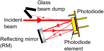
The general idea of photon recycling is depicted in Fig. 1. A part of the incident beam (the primary beam hereafter) is absorbed by the substrate of a PD, while the other part of the primary beam is reflected (the primary reflection). The primary reflection is sent back to the PD by the RM. This beam (the secondary beam) is again absorbed by the PD, increasing the EQE. A part of the secondary beam is reflected by the PD and becomes the secondary reflection. This photon recycling technique can be extended to multi-fold recycling as shown in the figure. The EQE with -fold photon recycling, , is represented as
where , , and are the inherent EQE of the PD, the reflectivity of the PD, and the reflectivity of the RM, respectively. Here, the incident angle of the recycled beams is assumed to be the same as that of the primary beam. The secondary beam gives the dominant term of the EQE increase, . When the folding number is increased, the eventual EQE approaches . If we consider the simplest case with zero scatter loss from the PD (i.e. , where is the internal QE of the PD), and a perfect RM (i.e. ), the external loss is recovered and the eventual EQE agrees with the internal QE ().
2 Backscatter
Scattered light can be a phase noise limit in sensitive optical setups like interferometers for precision measurement [16, 17, 18]. The backscatter from PDs is particularly difficult to mitigate as optical attenuation is, in most cases, not allowed. The best way to reduce the scattering is to make the spot size smaller than the aperture size of the PD and tilt the PD away from the incident beam. Photon recycling risks increasing the amount of the backscattered light. For example, when the RM is aligned to reflect the primary reflection back into the same path, the secondary reflection directly goes back to the main optical instrument along the path of the primary beam. In practice, the backscattered field is composed of the light of the primary and secondary beams. Our target is to reduce the contribution of the secondary beam to be smaller than the one from the primary beam. The Gaussian beam overlap of the back reflection can be sufficiently reduced by tilting the RM by a few degrees as well as through the careful design of the beam parameters, especially the divergence angle. The backscatter is a function of the scattering angle and depends on the surface condition of the PD. Although the characterization of the scattering requires experimental evaluation, the scattered field, in general, becomes smaller as the scattering angle becomes larger. Thus, reduction of the backscatter requires proper choice of the angle of the RM. In addition, the eventual reflection that exits from the PD must be blocked by a beam dump to prevent acoustic coupling from the environment.
3 Experimental setup
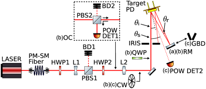
Figure 2 shows the experimental setup for demonstration and evaluation of photon recycling. Here a single-fold configuration is employed because we expect that the secondary beam dominantly contributes to both the enhancement of the EQE and the backscatter, owing to the inherent high EQE of the InGaAs PD. The target PD was an InGaAs PD with an active area of 3 mm (Excelitas, C30665GH), whose glass window was removed. The nominal incident angle () of the primary beam was 15 deg. The RM was a 12.7 mm mirror with a reflectivity higher than 0.995, and a concave radius of curvature (RoC) of 25 cm. The RM was placed at 20 mm from the PD to form single-fold photon recycling. With this reflection geometry, the loss caused by large angle scattering that could not be sent back into the PD was estimated to be by integrating the scattering shown in Fig. 4. To dump the secondary reflection, an iris was placed 50 mm upstream from the PD. The light source was a Nd:YAG NPRO laser (Lightwave Electronics, M126N-1064-500) with a wavelength of 1064 nm. The output beam went through a 5 m long polarization maintaining single-mode (PM-SM) fiber for spatial mode cleaning. The primary beam power was adjusted to be 11 mW by a half wave plate (HWP1) and a polarizing beam splitter (PBS1). The incident polarization on the PD was adjusted by another half wave plate (HWP2).
For reducing the Gaussian beam overlap between the primary and secondary beams, the divergence angle was designed to be less than 3% of the reflection angle (). This was also made large enough to reduce the contribution of the scatter from the secondary beam within the solid angle of the PD. Based on this criterion, we chose a beam separation of 1.5 mm. We placed the beam waist close to the PD to keep the beam size small enough for the PD. Consequently, was deg, the waist position was upstream of the PD by 50 mm, and the waist radii of the primary and secondary beams were and , respectively. Note that, depending on , was adjusted to keep the separation of the two beams (1.5 mm), and the secondary beam waist does not exist in the actual optical path (i.e. the the secondary beam waist is a virtual waist behind the RM). The waist sizes of the primary and secondary beams correspond to divergence angles of 0.24 deg and 0.11 deg, respectively, and the secondary beam’s divergence angle is less than 3% of . Two lenses, L1 and L2, and the RM were used to shape the beam. With this setup, the Gaussian beam overlap in this experiment was calculated to be negligibly small. As for the scattering, the contribution of the secondary beam with properly set was suppressed below the primary beam contribution as discussed later.
4 EQE measurement
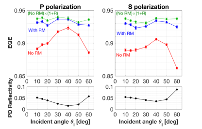
The EQE of the PD was measured with an incident angle of scanned from 10 – 60 deg. The EQEs were compared with and without the presence of the RM. The results for each incident polarization are shown in Fig. 3. The EQEs without the RM were measured to be 0.86 – 0.92, and the dependence on the PD reflectivity is clearly visible. The EQEs with the RM placed were measured to be 0.92 – 0.94 independently of the polarizations, showing enhancement of the EQE is less sensitive to the incident angle. If the scattering and reflection losses are negligible, the enhancement of the EQE with the RM is estimated to be and is shown in the figure. The difference between the incident angles of the primary and secondary beams changes the estimated values of the enhanced EQEs by less than 0.001 and can be neglected. The gap between the measured and estimated EQE with the RM is less than 0.01 for .
The statistical error of the EQE measurement comes from the fluctuation of the measurement values. Besides the statistical error plotted in the figure, the absolute level of the EQE has a systematic calibration error of 4%, which consists of the accuracy of the power meter for the incident power measurement (3%) and the accuracy of the transimpedance of the PD readout (2%). Although this calibration error may shift the curves up and down, this does not affect the relative difference between the measurements. The error of the reflectivity measurement is mainly composed of the 2% systematic error of measuring the laser power with the photodetector. This error is negligibly small in the figure.
5 Backscatter evaluation
To evaluate the backscatter, we measured the the amount of the backscattered light using an optical circulator and an optical chopper, as shown in Fig. 2-(b). The optical circulator was formed by a quarter wave plate (QWP) and polarizing beam splitter (PBS2) to separate backscattered light from the main beam path. The power of the separated light was measured by a power detector (POW DET; Thorlabs PDA100A). The chopper wheel (CW) was inserted downstream of PBS2 to modulate the incident light at 253 Hz, and the output of the power detector at the modulation frequency was obtained with a spectrum analyzer (Stanford Research Systems SR785). The optical chopping enables us to measure the reflected power at the modulation frequency where the dark noise of the detector is low. Also, the measurement removes the effects of spurious coupling of environmental illumination. The chopper in fact causes undesirable modulated reflection towards PBS2. Since the reflected field is P-polarized, PBS2 significantly attenuates it before it reaches the power detector.
For the purpose of evaluating the dependence of the backscattered light on the reflection angle , the measurements were carried out without the RM and with it placed at two different distances (20 mm and 50 mm) from the target PD. In the cases with the RM, separation between the two beams at the PD was kept to be 1.5 mm. These configurations correspond to of 4.3 deg and 1.7 deg, respectively.
| Distance of | Reflection | Backscatter reflectivity () | BRDF () | ||
|---|---|---|---|---|---|
| the RM (mm) | angle (deg) | Measured | Increment | Measured | Increment |
| No RM | — | — | — | ||
| 20 | 4.3 | ||||
| 50 | 1.7 | ||||
The measurement results are summarized in Table 1. When the reflection angle was 4.3 deg, there was no significant increase of the backscattered light observed, while the case with 1.7 deg caused a visible but minor increase of backscattered light. Thus, we can conclude that the secondary reflection does not produce a significant increase of the backscatter when the secondary beam is properly misaligned. Note that the errors were dominated by the systematic error of the power measurement for the incident power and the back scattered power.
6 BRDF measurement
The effect of the backscatter is also evaluated by the bidirectional reflectance distribution function (BRDF), i.e., scattered light power density per solid angle normalized by the incident power, as
where and are the incident and scattered light powers, respectively, is the detector subtending solid angle, and is the scattering angle [19]. In Table 1, the BRDF corresponding to the backscattered light measured with the setup shown in Fig. 2-(b) is presented.
The conclusion in the previous section can also be verified by examining the BRDF of the PD itself. This BRDF was measured with the setup shown in Fig. 2-(c). In the measurement, the primary beam was p-polarized at , and chopped at 253 Hz. The scattered light power was measured with the power detector placed at various scattering angles . In this BRDF measurement, sr (, ), sr (), and sr (). We adjusted considering the amount of light received by the power detector and the resolution of . In order to mitigate the influence of the scattering from the primary reflection, the primary reflection was blocked with a glass beam dump (GBD). The GBD consists of black welding glass and has low scattering thanks to its smooth surface.
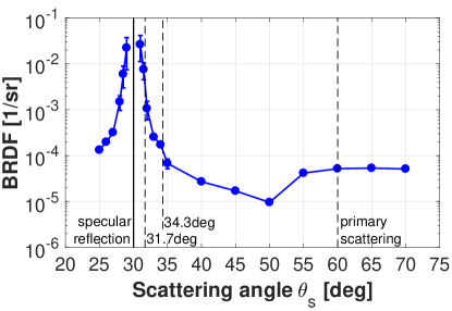
Figure 4 shows the measured BRDF of the PD. The remarkable feature is that the BRDF is high around . This angle corresponds to the specular reflection. Note that the measured points are located well outside of the Gaussian power distribution of the primary reflection. The BRDF falls rapidly with away from the specular reflection and becomes flat above .
Now we compare the contribution of the primary and secondary scattering to the BRDF. Since the measurement at was geometrically restricted by the input optics, we assume the BRDF is symmetric with regard to . Namely, we obtain BRDF(0 deg) = BRDF(60 deg) = . The contribution of the secondary beam is . For 4.3 deg and 1.7 deg, the contributions of the secondary are 1/sr and 1/sr, respectively. This means that the scattering from the secondary beam was successfully reduced below the one from the primary beam when the misalignment angle was properly set.
The primary scattering inferred from the BRDF is about a factor of 16 smaller than the one obtained from the direct backscatter measurement in the second experiment. This excess may indicate that the direct backscatter measurement could have been dominated by the scattering from the input optics located upstream of the PD. Nevertheless our conclusion about the comparison of the primary and secondary scattering remains unchanged.
7 Conclusion
The photon recycling technique allows reduction in external loss of the PD and an enhancement of the EQE for a PD towards the limitation set by the internal QE by adding a reflecting mirror close to the PD. The EQE for an InGaAs PD was enhanced by 0.01 – 0.06 from 0.86 – 0.92 over a wide range of incident angles. The enhancement of the EQE was consistent with the prediction from the reflectivity of the PD within 0.01 in a relatively small incident angle range. It was validated that the technique does not induce significant backscatter generated by the retro reflected scattered light when proper misalignment is used. Note that the amount of increased EQE is comparable to the ones in the previous experiments. The mitigation of backscatter, however, has never been investigated there.
The EQE enhancement with our technique can be applied within a spectral range determined by the characteristics of the PD materials. For example, when the absorption length of the diode is shorter than the thickness, an interference effect should be considered. However, if the absorption length is too short, the carrier-recombination effect may occur. If the PD thickness is long enough to neglect the carrier-recombination effect, the EQE can be enhanced over a broad wavelength range by a broadband dielectric mirror. We expect that our technique also enhances the EQE of silicon PDs in visible wavelengths and extended InGaAs PDs in the near infrared, e.g., 1.5 – 2.2 . It is also worth noticing that this technique requires a large enough diode to mitigate backscatter with wide reflection angle. This means that it is not effective to apply our technique to a PD with a small aperture, which is often used for the application at high frequencies, e.g., hundreds of megahertz.
This work was supported by the National Science Foundation under the LIGO cooperative agreement PHY-0757058. RXA also gratefully acknowledges funding provided by the Institute for Quantum Information and Matter, an NSF Physics Frontiers Center with support of the Gordon and Betty Moore Foundation.
References
- [1] P. K. Lam, T. C. Ralph, B. C. Buchler, D. E. McClelland, H.-a. Bachor, and J. Gao, “Optimization and transfer of vacuum squeezing from an optical parametric oscillator,” \JournalTitleJ. Opt. B: Quantum Semiclassical Opt. 1, 469–474 (1999).
- [2] LIGO Scientific Collaboration, “A gravitational wave observatory operating beyond the quantum shot-noise limit: Squeezed light in application,” \JournalTitleNat. Phys. 7, 962–965 (2011).
- [3] LIGO Scientific Collaboration, “Enhanced sensitivity of the LIGO gravitational wave detector by using squeezed states of light,” \JournalTitleNat. Photonics 7, 613–619 (2013).
- [4] C. Hicks, M. Kalatsky, R. a. Metzler, and A. O. Goushcha, “Quantum efficiency of silicon photodiodes in the near-infrared spectral range.” \JournalTitleAppl. Opt. 42, 4415–22 (2003).
- [5] D. Schroder, R. Thomas, and J. Swartz, “Free carrier absorption in silicon,” \JournalTitleIEEE Trans. Electron Devices 25, 254–261 (1978).
- [6] H. J. Hovel, Semiconductors and semimetals. Volume 11. Solar cells (Academic Press, Inc., New York, 1975).
- [7] B. E. A. Saleh and M. C. Teich, Fundamentals of photonics (Wiley: New York, 1991).
- [8] E. F. Zalewski and C. R. Duda, “Silicon photodiode device with 100% external quantum efficiency.” \JournalTitleAppl. Opt. 22, 2867–2873 (1983).
- [9] J. L. Gardner, “A four-element transmission trap detector,” \JournalTitleMetrologia 32, 469–472 (1995).
- [10] L. van Dijk, J. van de Groep, M. Di Vece, and R. E. I. Schropp, “Exploration of external light trapping for photovoltaic modules,” \JournalTitleOpt. Express 24, A1158–A1175 (2016).
- [11] M. S. Ünlü and S. Strite, “Resonant cavity enhanced photonic devices,” \JournalTitleJ. Appl. Phys. 78, 607–639 (1995).
- [12] M. Mehmet, S. Ast, T. Eberle, S. Steinlechner, H. Vahlbruch, and R. Schnabel, “Squeezed light at 1550 nm with a quantum noise reduction of 12.3 dB,” \JournalTitleOpt. Express 19, 25763–25772 (2011).
- [13] E. Waks, K. Inoue, W. D. Oliver, E. Diamanti, and Y. Yamamoto, “High-Efficiency Photon-Number Detection for Quantum Information Processing,” \JournalTitleIEEE J. Sel. Top. Quantum Electron. 9, 1502–1511 (2003).
- [14] C. Baune, J. Gniesmer, A. Schönbeck, C. E. Vollmer, J. Fiurášek, and R. Schnabel, “Strongly squeezed states at 532 nm based on frequency up-conversion,” \JournalTitleOpt. Express 23, 16035–16041 (2015).
- [15] H. Vahlbruch, M. Mehmet, K. Danzmann, and R. Schnabel, “Detection of 15 dB Squeezed States of Light and their Application for the Absolute Calibration of Photoelectric Quantum Efficiency,” \JournalTitlePhys. Rev. Lett. 117, 110801 (2016).
- [16] D. J. Ottaway, P. Fritschel, and S. J. Waldman, “Impact of upconverted scattered light on advanced interferometric gravitational wave detectors,” \JournalTitleOpt. Express 20, 8329–8336 (2012).
- [17] B. Canuel, E. Genin, G. Vajente, and J. Marque, “Displacement noise from back scattering and specular reflection of input optics in advanced gravitational wave detectors.” \JournalTitleOpt. Express 21, 10546–10562 (2013).
- [18] S. S. Y. Chua, S. Dwyer, L. Barsotti, D. Sigg, R. M. S. Schofield, V. V. Frolov, K. Kawabe, M. Evans, G. D. Meadors, M. Factourovich, R. Gustafson, N. Smith-Lefebvre, C. Vorvick, M. Landry, A. Khalaidovski, M. S. Stefszky, C. M. Mow-Lowry, B. C. Buchler, D. A. Shaddock, P. K. Lam, R. Schnabel, N. Mavalvala, and D. E. McClelland, “Impact of backscattered light in a squeezing-enhanced interferometric gravitational-wave detector,” \JournalTitleClass. Quantum Gravity 31, 035017 (2014).
- [19] C. Padilla, P. Fritschel, F. Magaña-Sandoval, E. Muniz, J. R. Smith, and L. Zhang, “Low scatter and ultra-low reflectivity measured in a fused silica window,” \JournalTitleAppl. Opt. 53, 1315–1321 (2014).