Emittance preservation of an electron beam in a loaded quasi-linear plasma wakefield
Abstract
We investigate beam loading and emittance preservation for a high-charge electron beam being accelerated in quasi-linear plasma wakefields driven by a short proton beam. The structure of the studied wakefields are similar to those of a long, modulated proton beam, such as the AWAKE proton driver. We show that by properly choosing the electron beam parameters and exploiting two well known effects, beam loading of the wakefield and full blow out of plasma electrons by the accelerated beam, the electron beam can gain large amounts of energy with a narrow final energy spread (%-level) and without significant emittance growth.
I Introduction
Beam driven plasma wakefield accelerators Chen et al. (1985) have the potential to offer compact linear accelerators with high energy gradients, and have been of interest for several decades. With a relativistic charged particle drive beam travelling through a plasma, a strong wakefield is excited that can be loaded by a trailing witness beam. When the witness beam optimally loads the wakefield, an increase in absolute energy spread can be kept small. The concept has been demonstrated experimentally in the past using electron drive beams accelerating electron witness beams Rosenzweig et al. (1988); Blumenfeld et al. (2007); Kallos et al. (2008); Litos et al. (2014).
A major challenge with plasma wakefield accelerators is, however, to accelerate a beam while keeping both energy spread and emittance growth small. In the well described linear regime, valid when the beam density is much smaller than the plasma density , a non-linear transverse focusing force causes emittance growth of the witness beam. The beam also sees a transversely and longitudinally varying accelerating field causing a spread in energy after the beam has been accelerated Katsouleas et al. (1987). In the non-linear regime, where , a bubble is formed by the transverse oscillations of the plasma electrons, gathering in a sheath around an evacuated area filled with only ions. The ions, assumed stationary, form a uniform density ion channel creating a focusing force that varies linearly with radius. This focusing force preserves emittance Rosenzweig et al. (1991).
In this paper we present simulation results showing how emittance preservation of a high charge density witness beam can be ensured when accelerated by a proton drive beam producing quasi-linear wakefields Rosenzweig et al. (2010). By quasi-linear wakefields we here mean wakefields with only partial blow out of the plasma electrons in the accelerating structure (bubble). The key idea is to have enough charge in the witness beam to at the same time load the wakefield to produce low relative energy spread, and completely blow out the electrons left in the accelerating structure after the beam to reach conditions that preserves emittance. The results have importance for the preparation of AWAKE Run 2 Adli and AWAKE Collaboration (2016), and possibly other applications in the quasi-linear regime.
I.1 AWAKE Run 2
.
The energy carried by electron drive beams used in previous plasma wakefield experiments have been on the order of and the propagation length typically no more than Blumenfeld et al. (2007); Caldwell et al. (2009). For high-energy physics application a higher total beam energy is often desired. For instance, the energy of a high-charge electron beam accelerated to with electrons, similar to the beam that could be produced by the International Linear Collider, is . Using electron beams as drivers, a large number of plasma stages is required to reach an energy of a for the accelerated beam. However, staging plasma accelerators without reducing the effective gradient and spoiling the beam quality is challenging Steinke et al. (2016); Lindstrøm et al. (2016).
Proton beams available at CERN carry significantly more energy than available electron beams, for the SPS beam Gschwendtner et al. (2016), allowing for much longer plasma wakefield accelerator stages. The SPS beam is orders of magnitude longer than the plasma wavelengths needed for such applications, and it does not drive a strong wake Gschwendtner et al. (2016). By letting the proton beam undergo self-modulation before injecting the witness beam into the accelerating structure, stronger wakefields are excited. The self-modulation is produced by the transverse fields generated by the beam acting upon itself, causing regions of the beam to rapidly defocus Kumar et al. (2010). The modulation frequency is close to that of the plasma electrons, and produces a train of short proton bunches along the beam axis with a surrounding halo of defocused particles. This train of bunches resonantly drives wakefields to large amplitudes.
AWAKE at CERN is a proof of concept proton beam driven plasma wakefield accelerator experiment AWAKE Collaboration et al. (2014), currently in its first phase of operation. The experiment uses a proton beam delivered by the SPS as its driver, and a single plasma stage with a nominal plasma density of Gschwendtner et al. (2016). This plasma density corresponds to and is matched to the transverse size of the proton beam such that Lu et al. (2005), where is the plasma wave number, , and is the plasma electron angular frequency.
The aim of the first phase of the experiment is to demonstrate self-modulation of the proton beam. The aim of the second phase, in 2018, is to sample the wakefield with a long electron beam (). The study presented here has relevance for Run 2 Adli and AWAKE Collaboration (2016), starting in 2021 after the LHC long shutdown 2, and aims to demonstrate acceleration of a short electron beam () to high energy and with a minimal increase in emittance and absolute energy spread.
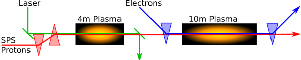
The plans for AWAKE Run 2 propose to use two plasma sections, as illustrated in Fig. 1. The first section of about is the self-modulation stage where the proton beam undergoes self-modulation without the electron beam present. The electron witness beam is then injected into the modulated proton beam before section two where it undergoes acceleration. The self-modulated proton beam does not produce a fully non-linear wakefield, and therefore not all plasma electrons are evacuated from the plasma bubble. The result is that the focusing force does not increase linearly with radius and the accelerated beam emittance is not preserved.
II Method
The focus in this study is on the beam loading of the wakefields driven by the proton beam. Studies of self-modulated proton beams show that the beam evolves as it propagates through a uniform plasma Lotov (2011), but small variations in the plasma profile the modulation, and thus the wakefields, may be stabilised over long distances Lotov (2011, 2015); Caldwell and Lotov (2011). To study the witness beam evolution in a stable wake, independent of the dynamics of the self-modulation, we use a single, non-evolving proton bunch as driver. The proton beam parameters are chosen so that key features of the wake –the plasma electron density in the wake and the longitudinal electric field –are the same as in the wake of a self-modulated proton beam with AWAKE baseline parameters Gschwendtner et al. (2016). Both the proton beam and the witness beam have Gaussian longitudinal charge distribution and bi-Gaussian transverse charge distributions.
We have previously studied the beam loading in a proton beam wake using the full particle-in-cell (PIC) code OSIRIS Fonseca et al. (2002) with 2D cylindrical-symmetric simulations. The studies Berglyd Olsen et al. (2015, 2016) primarily looked at beam loading, energy gain and energy spread, as well as different approaches to creating a stable drive beam structure based on previous self-modulation studies. In order to study the witness beam emittance evolution we use the recently released open-source version of QuickPIC Huang et al. (2006); An et al. (2013). QuickPIC is a fully relativistic 3D quasi-static PIC code. It does not suffer from the numerical Cherenkov effect that full PIC codes do Godfrey (1974); Lehe et al. (2013), making it a well suited tool to study emittance preservation. All simulation results in this paper were obtained using QuickPIC open-source UCLA Plasma Simulation Group (2017).
II.1 Drive Beam Parameters
The modulation process used in AWAKE does not reach the fully non-linear regime and thus does not produce a bubble void of plasma electrons. When the SPS beam, containing protons Gschwendtner et al. (2016), enters the second plasma section (Fig. 1), the peak electric field is expected to be about . The plasma electron density is only depleted to around of nominal value at the point where we inject the electron beam AWAKE Collaboration and Caldwell (2016). The plasma electron density depletion and the peak field are replicated using a single bunch with protons (), a length (), and a transverse size . The beam peak density is and results in a quasi-linear wake. To avoid transverse evolution of the proton driver, emulating the stable propagation of the self-modulated beam Lotov (2011, 2015); Caldwell and Lotov (2011), we freeze the transverse evolution of the equivalent proton bunch by increasing the particles mass by six orders of magnitude.
II.2 Witness Beam Parameters
In order to prevent large amplitude oscillations of the witness beam particles, which may cause additional energy spread as well as emittance growth, we consider a witness beam matched to the plasma density. The matched beam transverse size Esarey et al. (1996) is:
| (1) |
We assume an initial normalized emittance of . This emittance is possible to produce with a standard RF-injector, while at the same time yielding a sufficiently narrow beam.
Beam loading by a short witness beam is sensitive to its position relative to the electric field Tzoufras et al. (2009) as well as, at low energy, to its de-phasing with respect to the wakefields. To eliminate de-phasing of the witness beam, the initial beam energy is set such that , giving an energy of . A lower initial energy is likely to be sufficient for AWAKE Run 2 injection.
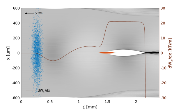
Equation (1) yields a transverse size of , which is narrow compared to the drive beam . The bunch length was set to based on earlier beam loading studies Berglyd Olsen et al. (2016). The charge is adjusted to for optimal beam loading, as discussed in the next section. We refer to the defined drive beam and witness beam parameter set as the base case. Figure 2 shows the two beams –the proton beam in blue, the trailing electron beam in red, and the plasma electron density in grey –from a QuickPIC simulation of the initial time step, for the base case parameters.
II.3 Simulation parameters
The relatively small size of the witness beam puts constraints on the transverse grid cell size and number in the simulations. We need a small size to resolve the narrow electron beam, and a large number of grid cells to resolve the much wider proton beam and its wakefields. We use a transverse grid cell size of , and of for the longitudinal grid cells for the simulations presented in section III. The witness beam was simulated with and the drive beam with non-weighted particles, and the plasma electrons with weighted particles per transverse slice.
III Beam Loading
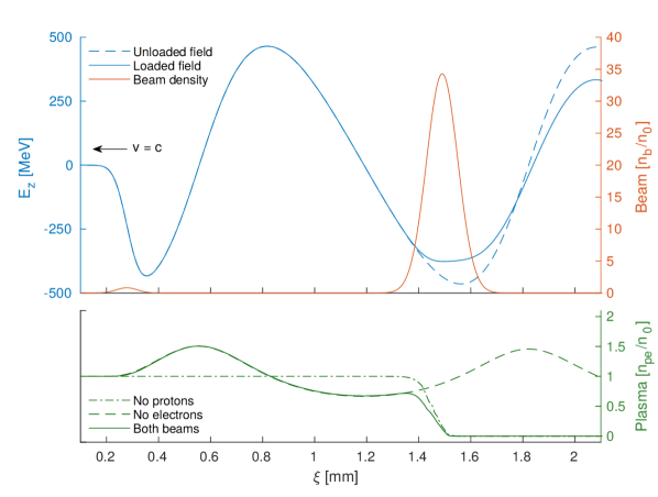
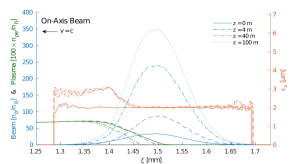
Figure 3 shows the results of QuickPIC simulations of the initial time step for the base case parameters. The -field generated by the proton drive beam is seen as the blue line, shown with and without the electron beam present. With a proton beam density , the wakefields are in the quasi-linear regime Rosenzweig et al. (2010). The dashed green line in the lower part of Fig. 3 shows that the on-axis plasma density has a depletion to , close to what we see in full scale reference simulations for AWAKE Run 2 AWAKE Collaboration and Caldwell (2016).
The witness beam generates its own wakefield that loads the -field generated by the drive beam. With an ideally shaped electron beam charge profile it is possible to optimally load the field in such a way that the accelerating field is constant along the beam Katsouleas et al. (1987); Tzoufras et al. (2009). Gaussian beams, as assumed in these studies, cannot completely flatten the electric field in the tails of the charge distribution, and our base case beam therefore has a tail in energy both at the front and the back of the beam, as illustrated in Fig. 4. The bulk of the beam, however, sees a relatively flat field.
The initial electron beam density is . This means that the witness beam’s own wakefield is in the fully non-linear regime, where the space charge force is sufficient to blow out all plasma electrons, resulting in the formation of a pure ion column (see Fig. 3, bottom). This ion column, as is well known Rosenzweig et al. (1991), provides a linear focusing force on the part the electron beam within the column, and therefore prevents emittance growth for this part of the beam. This bubble and the focusing force is shown for our base case in Fig. 2. The focusing field has a gradient of near the beam axis, corresponding to the matched field gradient.
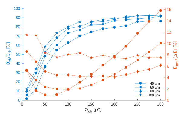

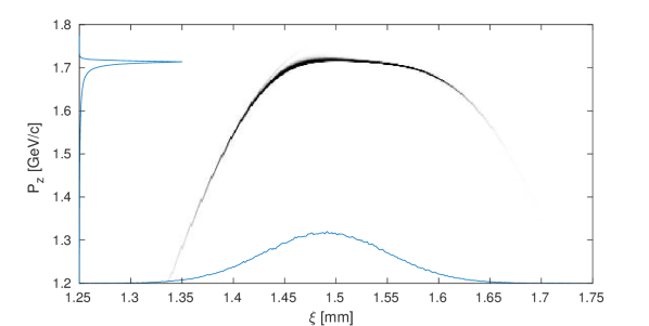
Figure 5 shows the slice emittance along the beam for the base case, sampled after propagating through , , and of plasma. We define emittance of a slice as preserved if the growth is less than , and as the sum charge of the slices for which the emittance is preserved. Simulation results show that of the electron beam longitudinal slices retain their initial emittance after the propagation in the plasma. The total (projected) emittance of these slices combined is also preserved. Emittance growth mainly occurs in the first few metres, and no significant emittance growth is observed after this for propagation lengths up to . The head of the beam does not benefit from the full ion column focusing, but since the proton beam creates a quasi-linear wake, the emittance of the head of the beam still stabilises after some time. For the simulation, the drive beam energy was increased to (LHC energy) to prevent de-phasing, as de-phasing starts to become a significant effect for the SPS beam of after about .
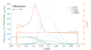
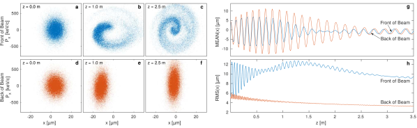
So far we have considered a witness beam injected on the axis of the proton beam. We now briefly examine the case of injection of a witness beam with an offset with respect to the proton beam axis. Since the witness beam creates its own plasma bubble, the emittance of the part of the beam inside that bubble is not affected by small transverse offsets of the witness beam with respect to the proton beam axis. This is illustrated in Fig. 5, right, for an electron beam offset of one . Emittance preservation for small offsets is an added benefit of this accelerating regime, and may ease transverse injection tolerances. The head of the beam experiences a larger initial emittance growth than for the on-axis case (compare Fig. 5, left, to Fig. 5, right). However, also for the head of the beam the emittance growth ends after the first few metres. Figure 6a-c show the phase space of the head of the electron beam after , and , while Fig. 6d-f show the phase space of the trailing part of the beam. The centroid oscillations of the head and the trailing part are shown in Fig. 6g. This effect of a transverse offset is greater for larger offsets as the beam oscillates around the axis of the drive beam wakefield.
The transverse beam size within the bubble, where normalised emittance is preserved, follows the evolution given by Eq. 1; that is, evolves to stay matched. The on-axis density of the electron beam, as a result, increases as its gamma factor increases and its transverse size decreases. This effect can be seen in Fig. 6h. This has the potential to cause overloading of the field. However, for the base case no significant overloading is observed. Parameters can also be chosen in order to minimise this effect by slightly underloading the wakefield at first, and let the high energy beam overload the wakefield at the end.
IV Parameter Optimisation
The beam loading and blow out properties of the electron beam depend on a large number of parameters, including longitudinal profile, transverse profile, as well as relative phasing of the proton and the electron beams. We present a limited parameter study aimed to guide beam parameter choices for AWAKE Run 2. For an electron beam to be externally injected in AWAKE Run 2 (see Fig. 1) it is desired to maximise the energy gain, minimise the energy spread, maximise the charge to be accelerated, and minimise the emittance growth Adli and AWAKE Collaboration (2016). In addition, the beam length should be such that it is possible to generate and transport the beam using a compact electron injector Adli and AWAKE Collaboration (2016). We investigate the interdependence of these parameters in simulation by varying the electron beam length, its charge, and initial emittance. The results are quantified in terms of how much of the beam retains its initial emittance. For these parameter scans we used a transverse grid cell size of , and let the beams propagate through of plasma.
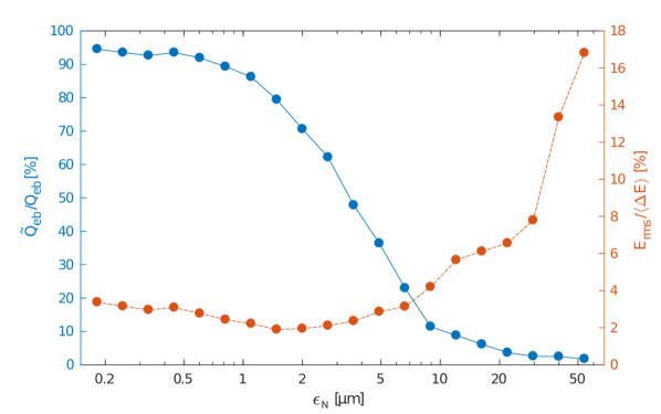
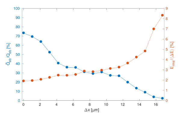
Figure 8 shows the dependence of charge and energy spread on witness beam length and incoming charge. An initial beam emittance of was used. Therefore, we define the fractional charge as the charge whose emittance remains smaller than . The beam charge ranges from to , and ranges from to . As can be seen from Fig. 8 (red curves), both the and the beams have a well defined minimum energy spread with an initial beam charge and , respectively. Lower beam charges tend to underload the electric field, while higher beam charges tend to overload it. It is also clear that longer beams with respect to the accelerating phase of the field, , do not optimally load the wake, thus producing a larger spread in energy. The blue curves show the fraction of charge whose initial emittance is preserved (the slice emittance for the base case is shown in Fig. 5). As the witness beam charge increases, the fraction of slices with preserved emittance increases –as expected from an earlier onset of the bubble formation –and also increases in the bubble size Lu et al. (2006a, b). We note here that operation with leads to a significantly larger charge (factor ) with emittance preserved, at the expense of an increase of relative energy spread by a factor of two.
Figure 8 shows the dependence of mean energy gain on beam length and beam charge (red curves). The blue curves show the amount of charge in the longitudinal slices where the emittance has been preserved, as a function of beam length and beam charge. The results are weakly dependent on the electron beam length. As expected, a larger value of corresponds to a lesser energy gain. No optimum is observed.
Figure 10 shows how the growth in emittance and energy spread varies with initial electron beam emittance. In these simulations we adjusted the witness beam radius to maintain the matching condition at each emittance. The smaller the initial emittance is, the better the emittance is preserved. There are two effects that lead to emittance growth for high initial emittance beams: the transverse beam size may increase beyond the size of the bubble, and the beam density may be reduced so much that the plasma electrons are no longer fully evacuated from the bubble. Emittance values higher than a few micrometres lead to a significant increase in both emittance and energy spread.
Our base case showed some robustness to a small offset from the proton beam axis on the order of one , but with a reduction of the fraction of the beam which retains its initial emittance. Figure 10 shows the correlation between this ratio for a range of offsets up to , corresponding to . The effect on the head of the beam, shown in Figs. 5 and 6, increases with larger offsets causing the part of the beam being defocused to extend backwards to the point where the witness beam wakefields are no longer in the blow-out regime. At around emittance is no longer preserved at all.
The optimal working point will depend on the application and must be studied for each case and is, as illustrated in this section, a trade off between beam length, beam charge and emittance preservation, as well as other parameters like the plasma density.
V Conclusion
We have devised a method to accelerate an electron witness beam to high energy with a low relative energy spread while maintaining its incoming emittance in wakefields such that the accelerating structure is not void of plasma electrons. This is the case for the AWAKE experiment in which the wakefields are driven by a train of proton bunches produce by self-modulation of a long proton beam. This method is in principle applicable to all experiments operating in the quasi-linear regime. Low relative energy spread and emittance preservation are achieved by choosing the electron beam parameters to load the wakefields and evacuate the remaining plasma electrons from the accelerating structure.
Parameter studies indicate that for up to a few , about of the incoming beam charge is accelerated for beam of lengths of . Such electron beams may be generated by an injector based on a standard RF photo-emission gun Doebert (2017).
In order to use manageable computer time for simulations, this study assumes a simplified case with respect to a self-modulated proton beam, where the wake is driven by a single, short proton bunch producing similar wakefields. However, the wakefields driven by a train of bunches evolve with the ramp of a real plasma and when entering the plasma. Therefore, to be fully applicable to an experiment such as AWAKE, the study will have to be redone with more realistic parameters. However, using loading of the wakefields and the pure plasma ion column fields to produce an accelerated beam with low relative energy spread and emittance remains applicable.
VI Acknowledgements
The simulations for this study have been performed using the open source version of QuickPIC released in early 2017 and owned by UCLA.
These numerical simulations have been made possible through access to the Abel computing cluster in Oslo, Norway. Abel is maintained by UNINETT Sigma2 AS and financed by the Research Council of Norway, the University of Bergen, the University of Oslo, the University of Tromsø and the Norwegian University of Science and Technology. Project code: nn9303k. Some of the simulations were also run on the student-maintained computing cluster Smaug at the University of Oslo, Department of Physics.
We gratefully acknowledge helpful discussions with Jorge Vieira from IST, Lisbon.
References
- Chen et al. (1985) P. Chen, J. M. Dawson, R. W. Huff, and T. Katsouleas, Physical Review Letters 54, 693 (1985).
- Rosenzweig et al. (1988) J. B. Rosenzweig, D. B. Cline, B. Cole, H. Figueroa, W. Gai, R. Konecny, J. Norem, P. Schoessow, and J. Simpson, Physical Review Letters 61, 98 (1988).
- Blumenfeld et al. (2007) I. Blumenfeld, C. E. Clayton, F.-J. Decker, M. J. Hogan, C. Huang, R. Ischebeck, R. Iverson, C. Joshi, T. Katsouleas, N. Kirby, W. Lu, K. A. Marsh, W. B. Mori, P. Muggli, E. Oz, R. H. Siemann, D. Walz, and M. Zhou, Nature 445, 741 (2007).
- Kallos et al. (2008) E. Kallos, T. Katsouleas, W. D. Kimura, K. Kusche, P. Muggli, I. Pavlishin, I. Pogorelsky, D. Stolyarov, and V. Yakimenko, Physical Review Letters 100, 074802 (2008).
- Litos et al. (2014) M. Litos, E. Adli, W. An, C. I. Clarke, C. E. Clayton, S. Corde, J. P. Delahaye, R. J. England, A. S. Fisher, J. Frederico, S. Gessner, S. Z. Green, M. J. Hogan, C. Joshi, W. Lu, K. A. Marsh, W. B. Mori, P. Muggli, N. Vafaei-Najafabadi, D. Walz, G. White, Z. Wu, V. Yakimenko, and G. Yocky, Nature 515, 92 (2014).
- Katsouleas et al. (1987) T. Katsouleas, S. Wilks, P. Chen, J. M. Dawson, and J. J. Su, Particle Accelerators 22, 81 (1987).
- Rosenzweig et al. (1991) J. B. Rosenzweig, B. Breizman, T. Katsouleas, and J. J. Su, Physical Review A 44, R6189 (1991).
- Rosenzweig et al. (2010) J. B. Rosenzweig, G. Andonian, M. Ferrario, P. Muggli, O. Williams, V. Yakimenko, and K. Xuan, AIP Conference Proceedings 1299, 500 (2010).
- Adli and AWAKE Collaboration (2016) E. Adli and AWAKE Collaboration, in Proceedings of IPAC 2016, International Particle Accelerator Conference (JACoW, Busan, Korea, 2016) pp. 2557–2560.
- Berglyd Olsen et al. (2015) V. K. Berglyd Olsen, E. Adli, P. Muggli, L. D. Amorim, and J. Vieira, in Proceedings of IPAC 2015 (Richmond, VA, USA, 2015) pp. 2551–2554.
- Caldwell et al. (2009) A. Caldwell, K. Lotov, A. Pukhov, and F. Simon, Nature Physics 5, 363 (2009).
- Steinke et al. (2016) S. Steinke, J. van Tilborg, C. Benedetti, C. G. R. Geddes, C. B. Schroeder, J. Daniels, K. K. Swanson, A. J. Gonsalves, K. Nakamura, N. H. Matlis, B. H. Shaw, E. Esarey, and W. P. Leemans, Nature 530, 190 (2016).
- Lindstrøm et al. (2016) C. A. Lindstrøm, E. Adli, J. M. Allen, J. P. Delahaye, M. J. Hogan, C. Joshi, P. Muggli, T. O. Raubenheimer, and V. Yakimenko, Nuclear Instruments and Methods in Physics Research Section A 829, 224 (2016).
- Gschwendtner et al. (2016) E. Gschwendtner, E. Adli, L. Amorim, R. Apsimon, R. Assmann, A. M. Bachmann, F. Batsch, J. Bauche, V. K. Berglyd Olsen, M. Bernardini, R. Bingham, B. Biskup, T. Bohl, C. Bracco, P. N. Burrows, G. Burt, B. Buttenschön, A. Butterworth, A. Caldwell, M. Cascella, E. Chevallay, S. Cipiccia, H. Damerau, L. Deacon, P. Dirksen, S. Doebert, U. Dorda, J. Farmer, V. Fedosseev, E. Feldbaumer, R. Fiorito, R. Fonseca, F. Friebel, A. A. Gorn, O. Grulke, J. Hansen, C. Hessler, W. Hofle, J. Holloway, M. Hüther, D. Jaroszynski, L. Jensen, S. Jolly, A. Joulaei, M. Kasim, F. Keeble, Y. Li, S. Liu, N. Lopes, K. V. Lotov, S. Mandry, R. Martorelli, M. Martyanov, S. Mazzoni, O. Mete, V. A. Minakov, J. Mitchell, J. Moody, P. Muggli, Z. Najmudin, P. Norreys, E. Öz, A. Pardons, K. Pepitone, A. Petrenko, G. Plyushchev, A. Pukhov, K. Rieger, H. Ruhl, F. Salveter, N. Savard, J. Schmidt, A. Seryi, E. Shaposhnikova, Z. M. Sheng, P. Sherwood, L. Silva, L. Soby, A. P. Sosedkin, R. I. Spitsyn, R. Trines, P. V. Tuev, M. Turner, V. Verzilov, J. Vieira, H. Vincke, Y. Wei, C. P. Welsch, M. Wing, G. Xia, and H. Zhang, Nuclear Instruments and Methods in Physics Research Section A 829, 76 (2016).
- Kumar et al. (2010) N. Kumar, A. Pukhov, and K. Lotov, Physical Review Letters 104, 255003 (2010).
- AWAKE Collaboration et al. (2014) AWAKE Collaboration, R. Assmann, R. Bingham, T. Bohl, C. Bracco, B. Buttenschön, A. Butterworth, A. Caldwell, S. Chattopadhyay, S. Cipiccia, E. Feldbaumer, R. A. Fonseca, B. Goddard, M. Gross, O. Grulke, E. Gschwendtner, J. Holloway, C. Huang, D. Jaroszynski, S. Jolly, P. Kempkes, N. Lopes, K. Lotov, J. Machacek, S. R. Mandry, J. W. McKenzie, M. Meddahi, B. L. Militsyn, N. Moschuering, P. Muggli, Z. Najmudin, T. C. Q. Noakes, P. A. Norreys, E. Öz, A. Pardons, A. Petrenko, A. Pukhov, K. Rieger, O. Reimann, H. Ruhl, E. Shaposhnikova, L. O. Silva, A. Sosedkin, R. Tarkeshian, R. M. G. N. Trines, T. Tückmantel, J. Vieira, H. Vincke, M. Wing, and G. Xia, Plasma Physics and Controlled Fusion 56, 084013 (2014).
- Lu et al. (2005) W. Lu, C. Huang, M. M. Zhou, W. B. Mori, and T. Katsouleas, Physics of Plasmas 12, 063101 (2005).
- Lotov (2011) K. V. Lotov, Physics of Plasmas 18, 024501 (2011).
- Lotov (2015) K. V. Lotov, Physics of Plasmas 22, 103110 (2015).
- Caldwell and Lotov (2011) A. Caldwell and K. V. Lotov, Physics of Plasmas 18, 103101 (2011).
- Fonseca et al. (2002) R. A. Fonseca, L. O. Silva, F. S. Tsung, V. K. Decyk, W. Lu, C. Ren, W. B. Mori, S. Deng, S. Lee, T. Katsouleas, and J. C. Adam, in Computational Science — ICCS 2002, Lecture Notes in Computer Science No. 2331, edited by P. M. A. Sloot, A. G. Hoekstra, C. J. K. Tan, and J. J. Dongarra (Springer Berlin Heidelberg, 2002) pp. 342–351.
- Berglyd Olsen et al. (2016) V. K. Berglyd Olsen, E. Adli, P. Muggli, and J. Vieira, in Proceedings of NAPAC 2016 (Chicago, IL, USA, 2016).
- Huang et al. (2006) C. Huang, V. K. Decyk, C. Ren, M. Zhou, W. Lu, W. B. Mori, J. H. Cooley, T. M. Antonsen, and T. Katsouleas, Journal of Computational Physics 217, 658 (2006).
- An et al. (2013) W. An, V. K. Decyk, W. B. Mori, and T. M. Antonsen, Journal of Computational Physics 250, 165 (2013).
- Godfrey (1974) B. B. Godfrey, Journal of Computational Physics 15, 504 (1974).
- Lehe et al. (2013) R. Lehe, A. Lifschitz, C. Thaury, V. Malka, and X. Davoine, Physical Review Special Topics - Accelerators and Beams 16, 021301 (2013).
- UCLA Plasma Simulation Group (2017) UCLA Plasma Simulation Group, “QuickPIC-OpenSource,” GitHub repository (2017).
- AWAKE Collaboration and Caldwell (2016) AWAKE Collaboration and A. Caldwell, AWAKE Status Report, 2016, Tech. Rep. CERN-SPSC-2016-033 (CERN, Geneva, 2016).
- Esarey et al. (1996) E. Esarey, P. Sprangle, J. Krall, and A. Ting, IEEE Transactions on Plasma Science 24, 252 (1996).
- Tzoufras et al. (2009) M. Tzoufras, W. Lu, F. S. Tsung, C. Huang, W. B. Mori, T. Katsouleas, J. Vieira, R. A. Fonseca, and L. O. Silva, Physics of Plasmas 16, 056705 (2009).
- Lu et al. (2006a) W. Lu, C. Huang, M. Zhou, W. B. Mori, and T. Katsouleas, Physical Review Letters 96, 165002 (2006a).
- Lu et al. (2006b) W. Lu, C. Huang, M. Zhou, M. Tzoufras, F. S. Tsung, W. B. Mori, and T. Katsouleas, Physics of Plasmas (1994-present) 13, 056709 (2006b).
- Doebert (2017) S. Doebert, private correspondence (2017).