Simulating the Injection of Magnetized Plasma without Electromagnetic Precursor Wave
keywords:
Particle-in-Cell , Magnetized , Collisionless Plasma , Electromagnetic Simulation , Boundary Condition1 Introduction
This note aims to explain how to inject magnetized plasma through an open boundary into the simulation domain of a particle-in-cell simulation. If the magnetic field at the boundary is constant in time, i.e., if magnetized plasma of constant magnetization is injected at a steady rate, this does not present any challenges beyond injecting the particles at a fixed rate and possibly absorbing plasma waves impinging on the wall. If, however, the magnetization or the injection rate changes, a time-varying magnetic field is present. The classical use case for this scenario is a shock front moving through a plasma into the simulation volume.
The time variation in magnetic field obviously produces a curl of the electric field. This new electric field in turn produces a magnetic field of its own. Or in other words, an electromagnetic wave is launched. This effect might be desired in the implementation of antennas that launch electromagnetic radiation into the simulation domain. When injecting magnetized plasma this high frequency effect is undesired and might – depending on the amplitude of the wave – produce unphysical or at least undesired effects in the medium ahead of the injected material. From observations [1, 2, 3] it is known that shock waves do not continouosly emit electromagnetic radiation ahead of the shock front, which is what should be reproduced in sumulations. The goal is, therefore, to find an injection method that is capable of handling time variable magnetic fields at the injection site without launching an electromagnetic percursor wave.
Both antennas and injection of magnetized plasma is often performed by prescribing a current density instead of directly setting the magnetic field. This has the advantage that the resulting magnetic field is automatically divergence free as it is calculated from Ampere’s Law.
One example of using a current pulse to push magnetized plasma is given in [4]. The authors there also note that the shape of the current pulse is not arbitrary, but has to be chosen carefully to avoid the generation of a precursor wave. Their choice for the injection profile was a cosine half wave switching smoothly from zero to a desired value and subsequently holding that value constant. Two different period lengths of the cosine are discussed, and , where is the electron plasmafrequency at the initial, uncompressed density. The first case works well as a driver, but still launches a visible electromagnetic wave. The slower injection of the latter case avoids this effect. Additionally, the current is not injected in a single location, but over a finite spatial range of 14 Debye lengths, which helps to reduce high noise, equivalent to high frequency waves.
Another example of a time variable magnetic field that passes the boundaries of the simulation domain is presented in [5]. In that case, a non-homogeneous magnetic field is considered, combined with a moving simulation domain that tracks a bunch of particles. This application, however, uses an electrostatic plasma model, that is free from electromagnetic waves by construction.
In many other cases only unmagnetized plasma is injected and magnetic fields are only present in the simulation domain through the self-consistent interaction with the ambient plasma. Typical examples can be found in [6] and references therein, especially [7].
All the tests of the injection method presented below in section 2 were performed with the electromagnetic particle-in-cell code ACRONYM [8]. It is a fully-parallelized code for the simulation of collisionless plasma phenomena using standard algorithms of second order accuracy in space and time. Electromagnetic fields are stored in a standard Yee ([9]) grid. Particles are updated using the Boris push [10, 11]. The current density that results from the movements of the charge particles is deposited onto the grid using the method of Esirkepov [12]. This deposition, as well as the interpolation of the electromagnetic fields to the particle position, use the second order interpolation using a TSC shape function. The code allows to use any of the different FDTD schemes listed in [13] to calculate the update of the electromagnetic fields. However, for the purpose of this note, only the standard second-order scheme is used, that uses a straightforward approximation of the curl using four terms in the expression for central differences. The open boundary through which the magnetized plasma is injected discards any particles that might reach it from the simulation domain. All incoming waves are absorbed by a perfectly matched layer (PML, see [14]). More precisely, a PML with a complex frequency shift is used, that is implemented using time domain equations following the convolutional PML scheme described in [15].
2 Method
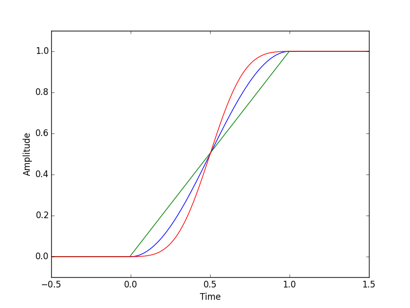
The electric field of the precursor wave is produced by the change in time of the magnetic field. An obvious approach to remove the precursor is thus to feed the injected magnetic field through a low pass filter to remove the steep rise. In more technical terms, the derivative of the magnetic field, is convolved with a digital low pass filter and then running sum of the resulting signal is applied on the boundary. Figure 1(a) shows the resulting amplitude of the supplied magnetic field at the boundary of the simulation domain as a function of time.
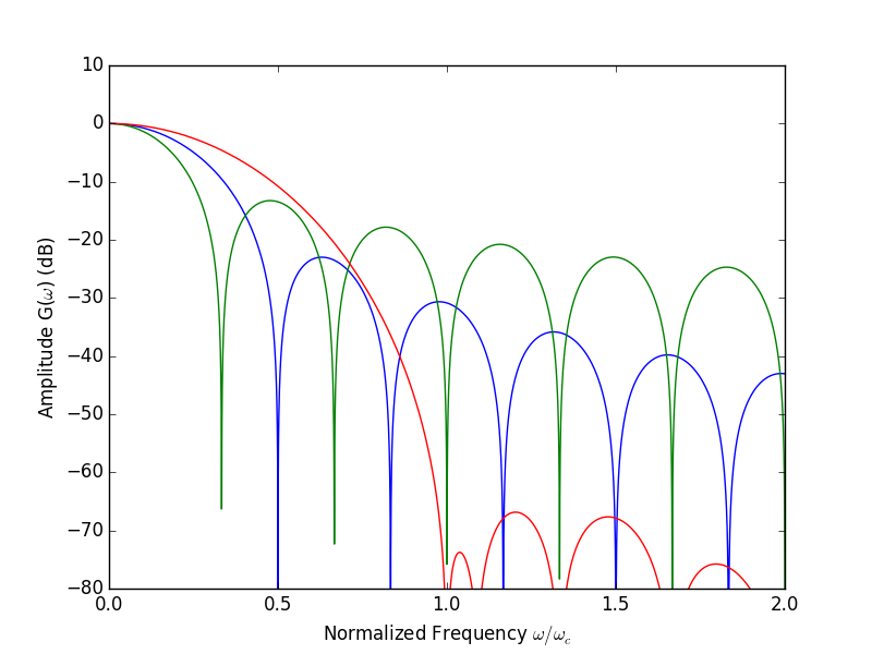
To see the effective reduction of high frequency components that could propagate through the plasma, it is useful to also plot the frequency dependence of the transfer function of the low pass filter. This is shown in figure 1(b). Alternatively, this can be seen as the amplitude of the waves launched at the boundary as a function of frequency.
The simplest digital low pass filter is the moving average filter, that splits up the change in magnetic field equally over time steps. In figure 1 this is indicated by a solid green line. The sharp step function in magnetic field is replaced by a linear increase and, as the plot over frequency shows, amplitudes are reduced at higher frequencies.
Slightly more complicated digital filters are also available. One possible choice is the sinusoidal half wave that was also used by [4], indicated in red.
The preferred solution is the use of a minimum 3-term Blackman-Harris window. This filter has the strongest suppresion of high-frequency components above the cut-off frequency for any filter that inject over a number of steps . (see [16] for a review of suitable digital filters). As figure 1(b) shows, there is practically no components above a critical frequency . This critical frequency depends on the number of steps and their length through
| (1) |
For comparison, the critical frequency of the rectangular window of a moving average filter is given by
| (2) |
Figure 1 uses identical values of for all windows, which explain why the moving average filter has its critical frequency at about one third of the critical frequency of the Blackman-Harris window. However, it still shows much larger amplitude, as the maximum attenuation is much lower.
For the sinusoidal window, the critical frequency is
| (3) |
but the damping of high frequencies is not much better than for the moving average filter.
The crucial step now is to make sure that the critical frequency is below the gyro frequency of electrons . All waves with frequencies above the critical frequency are suppressed by the injection method. All waves with frequencies close to the gyro frequency are strongly damped through interaction with gyrating electrons (see [17, 18]).

To get even better results, it is advisable to inject the magnetic field not at a single point, but through the entire thickness of the perfectly matched layer. This removes the effect that the PML absorbs some of the injected magnetic field, which makes injection of a well determined magnetic field hard. Furthermore, it reduces the energy available to modes at large that might propagate as high frequency waves into the simulation box.
Listing 1 below shows how the signal supplied by the user can be passed through the low pass filter to result in a filtered signal that contains no components above .
In the above implementation the Blackman-Harris window has to be normalized, i.e., all entries have to sum to one. The described form is not the only possible design. For example the code above implements a zero phase filter without lag. If the user supplied function is not know ahead of time, it might be necessary to switch to a causal, linear-phase filter that delays the input signal by timesteps.
2.1 Example case
The main application that is driving the development of this method has been the injection of magnetized shocks into a simulation box. Observations from e.g. the Sun have shown that plasma shocks will travel through bulk plasma without constantly emitting EM noise. It has also been shown that these plasma shocks have a finite width.
A correctly modeled injection of a shock should show its propagation through the medium without the emission of an EM emission when entering the box. Unfortunately a comparison with other methods is difficult. The main reason for this is that shock simulations have been performed in a very different setup in the recent years: The generally used methods [19] uses a box with a wall on one side, where a plasma stream is reflected, which leads to a subsequent shock front. This model is used, since the injection of a magnetized plasma stream from one face of the box is not working well and is typically too expensive.
Since a direct comparison of shock-like injection to other codes is not possible, we will use a different benchmarking technique: Since the EM noise moves away from the shock at the speed of light, the benchmark is that the shock structure in the filtered and the unfiltered version (after the EM pulse has moved away) will be unaltered.
To demonstrate the performance of the suggested injection method we have simulated the injection of particles into a vacuum, initially without magnetic field. After some time we switch on a magnetic field pointing perpendicular to the flow direction. This setup is simulated with an instantaneous step function as well as a filtered injection.
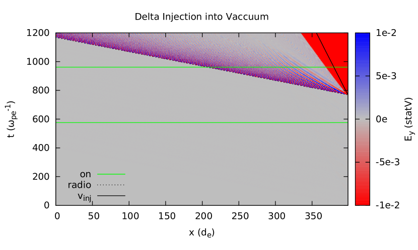
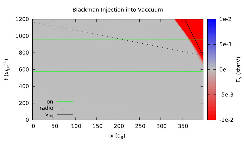
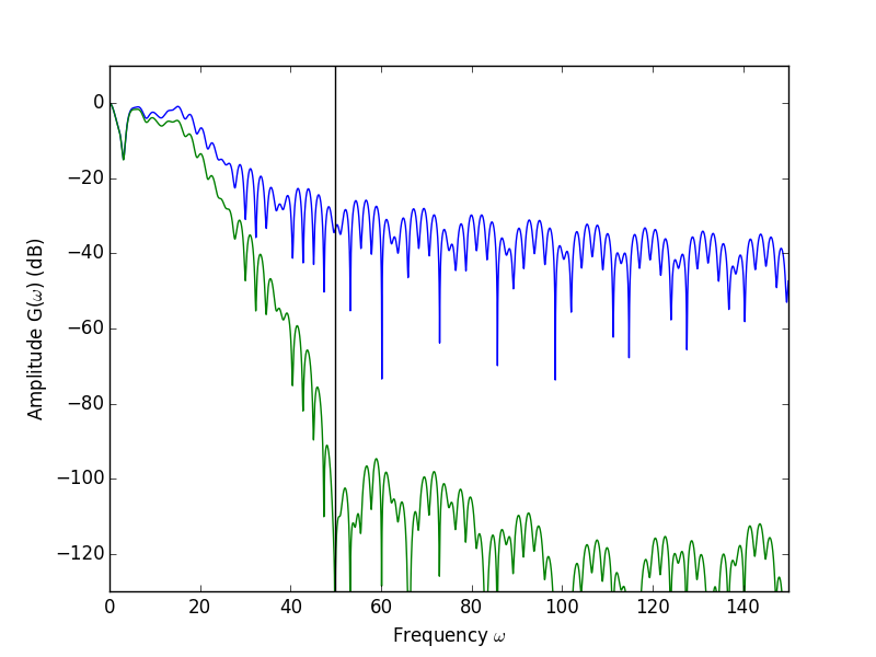
Figure 3 shows the results in both cases. In the left panel 3(a) the injection with the sudden step is shown. The electric field perpendicular to the flow direction and the magnetic field shows a clear signature of a signal propagating at the speed of light. The amplitude of this signal is , significantly larger than the convective electric field caused by the term of the streaming magnetized plasma.
In the right panel 3(b) the same situation is simulated again, but with a filtered injection. The precursor waves is absent in this case and only the convective electric field is visible. The noise level from the finite number of computiational particles is and even on that scale no precursor is detectable. This shows that the digital low pass filter attenuates the unphysical precursor wave by at least 50 dB.
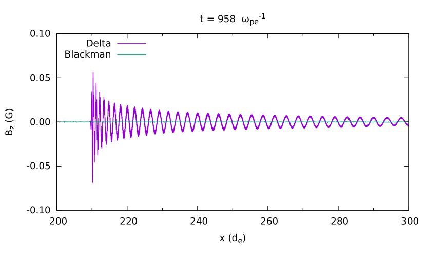
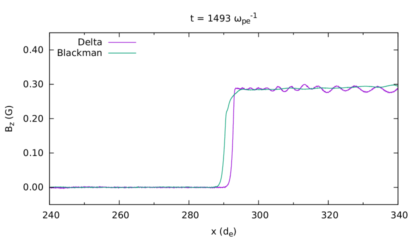
Figure 4 shows two snapshot containing the precursor wave and the desrired shock front and compare between the step injection and the filtered injection. It can be easily seen that the actual shock region is unaffected by the filtering while the unphysical EM pulse is removed from the simulation domain.
In conclusion we report that standard digital low pass filters are suitable to remove high frequency components from the wave form of the magnetic field applied at a boundary. Selecting a cut-off frequency close to the gyro frequency of the plasma leads to good results, without undesired precursor waves. In principle different digital filters can be used, but the use of a Blackman-Harris window offers very good performance at low numerical effort. If necessary a Dolph-Chebyshev window would offer moderately better performance but the filter coefficients are much harder to generate. Simpler windows of a moving-average filter did not produce satisfactory results.
Acknowledgment
The authors would like to thank Patricio Munoz for useful discussions and feedback on an earlier version of this manuscript. We acknowledge the use of the ACRONYM code supplied by its developers (Verein zur Förderung kinetischer Plasmasimulationen e.V.). The authors gratefully acknowledge the Gauss Centre for Supercomputing e.V. (www.gauss-centre.eu) for funding this project (pr74se) by providing computing time on the GCS Supercomputer SuperMUC at Leibniz Supercomputing Centre (www.lrz.de). This work is based upon research supported by the National Research Foundation and Department of Science and Technology. Any opinion, findings and conclusions or recommendations expressed in this material are those of the authors and therefore the NRF and DST do not accept any liability in regard thereto.
References
References
- [1] M. Dryer, Interplanetary Shock Waves Generated by Solar Flares, Space Science Reviews 15 (1974) 403–468. doi:10.1007/BF00178215.
- [2] R. A. Howard, D. J. Michels, N. R. Sheeley, Jr., M. J. Koomen, The observation of a coronal transient directed at earth, The Astrophysical Journal Letters 263 (1982) L101–L104. doi:10.1086/183932.
- [3] S. J. Schwartz, M. F. Thomsen, S. J. Bame, J. Stansberry, Electron heating and the potential jump across fast mode shocks, Journal of Geophysical Research 93 (1988) 12923–12931. doi:10.1029/JA093iA11p12923.
- [4] B. Lembege, J. M. Dawson, Self‐consistent study of a perpendicular collisionless and nonresistive shock, The Physics of Fluids 30 (6) (1987) 1767–1788. doi:10.1063/1.866191.
- [5] T. Hurtig, N. Brenning, M. A. Raadu, Three-dimensional electrostatic particle-in-cell simulation with open boundaries applied to a plasma beam entering a curved magnetic field, Physics of Plasmas 10 (11) (2003) 4291–4305. doi:10.1063/1.1619381.
- [6] K. Ardaneh, D. Cai, K.-I. Nishikawa, Collisionless electron–ion shocks in relativistic unmagnetized jet–ambient interactions: Non-thermal electron injection by double layer, The Astrophysical Journal 827 (2) (2016) 124.
- [7] K.-I. Nishikawa, P. Hardee, G. Richardson, R. Preece, H. Sol, , G. J. Fishman, Particle acceleration in relativistic jets due to weibel instability, The Astrophysical Journal 595 (1) (2003) 555–563.
- [8] P. Kilian, T. Burkart, F. Spanier, The influence of the mass ratio on particle acceleration by the filamentation instability, in: W. E. Nagel, D. B. Kröner, M. M. Resch (Eds.), High Performance Computing in Science and Engineering ’11, Springer, Berlin Heidelberg, 2012, pp. 5–13.
- [9] K. Yee, Numerical solution of inital boundary value problems involving maxwell’s equations in isotropic media, Antennas and Propagation, IEEE Transactions on 14 (3) (1966) 302–307.
- [10] J. P. Boris, Relativistic plasma simulation—optimization of a hybrid code, in: J. Boris, R. Shanny (Eds.), Proceedings of the Fourth Conference on the Numerical Simulation of Plasmas, Washington DC, Naval Research Laboratory, Washington DC, 1970, pp. 3–67.
- [11] G. Penn, P. H. Stoltz, J. R. Cary, J. Wurtele, Boris push with spatial stepping, Journal of Physics G: Nuclear and Particle Physics 29 (8) (2003) 1719–1722.
- [12] T. Z. Esirkepov, Exact charge conservation scheme for particle-in-cell simulation with an arbitrary form-factor, Computer Physics Communications 135 (2) (2001) 144 – 153. doi:10.1016/S0010-4655(00)00228-9.
- [13] J.-L. Vay, C. Geddes, E. Cormier-Michel, D. Grote, Numerical methods for instability mitigation in the modeling of laser wakefield accelerators in a lorentz-boosted frame, Journal of Computational Physics 230 (15) (2011) 5908 – 5929. doi:10.1016/j.jcp.2011.04.003.
- [14] J.-P. Berenger, A perfectly matched layer for the absorption of electromagnetic-waves, Journal of Computational Physics 114 (2) (1994) 185–200.
- [15] J.-P. Berenger, Perfectly matched layer (pml) for computational electromagnetics, Synthesis Lectures on Computational Electromagnetics 2 (1) (2007) 1–117. doi:10.2200/S00030ED1V01Y200605CEM008.
- [16] F. J. Harris, On the use of windows for harmonic analysis with the discrete fourier transform, Proceedings of the IEEE 66 (1) (1978) 51–83. doi:10.1109/PROC.1978.10837.
- [17] S. P. Gary, K. Nishimura, Kinetic alfvén waves: Linear theory and a particle-in-cell simulation, Journal of Geophysical Research: Space Physics 109 (A2). doi:10.1029/2003JA010239.
- [18] C. Schreiner, P. Kilian, F. Spanier, Recovering the damping rates of cyclotron damped plasma waves from simulation data, Communications in Computer Physics 21 (4). doi:10.4208/cicp.OA-2016-0091.
- [19] Y. A. Gallant, M. Hoshino, A. B. Langdon, J. Arons, C. E. Max, Relativistic, perpendicular shocks in electron-positron plasmas, The Astrophysical Journal 391 (1992) 73–101. doi:10.1086/171326.