Guiding of charged particle beams in curved capillary-discharge waveguides
Abstract
A new method able to transport charged particle beams along curved paths is presented. It is based on curved capillary-discharge waveguides in which the induced azimuthal magnetic field is used both to focus the beam and keep it close to the capillary axis. We show that such a solution is highly tunable, it allows to develop compact structures providing large deflecting angles and, unlike conventional solutions based on bending magnets, preserves the beam longitudinal phase space. The latter feature, in particular, is very promising when dealing with ultra-short bunches for which non-trivial manipulations on the longitudinal phase spaces are usually required when employing conventional devices.
Nowadays there is a growing interest in the development of new devices able to deflect charged particle beams with ever greater energies. In accelerator facilities, dipole magnets are widely used to realize bends and translate the beam to a specific location Reiser (2008); Bryant and Johnsen (2005); Leemann et al. (2009) and for the generation of synchrotron radiation Sokolov and Ternov (1966); Helliwell (1998), with a broad range of applications Brown and Sturchio (2002); Weik et al. (2000); Lewis (1997); Suortti and Thomlinson (2003). So far permanent and electromagnetic devices have been extensively employed although different solutions, e.g. based on channeling Gemmell (1974); Dabagov et al. (2015), have been proposed. Superconducting magnets Tomita and Murakami (2003) are at the edge of present technology and NbTi superconductors cooled at cryogenic temperatures represent the state of the art. They are routinely used, for instance, at the Large Hadron Collider (LHC) where more than 2/3 of the 27 km-long ring is filled by 8 T superconducting dipole magnets Todesco et al. (2004); Evans and Bryant (2008) in order to bend the 7 TeV proton beams. With current limits of superconducting technology, it is difficult to envision compact solutions that can be scaled to even greater energies and/or larger deflection angles.
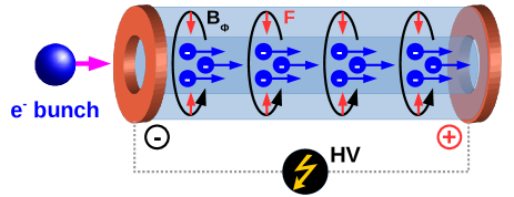
In this context plasmas represent an alternative approach. They can sustain extremely high fields Tajima and Dawson (1979) and currents Rocca et al. (1993, 1996); Tomasel et al. (1997); Hosokai et al. (2000) and, for these reasons, today they are replacing conventional accelerators Leemans et al. (2006); Blumenfeld et al. (2007) and standard focusing devices Su et al. (1990); Boggasch et al. (1992); Hairapetian et al. (1994). Recently, several proof of principle experiments have been performed in focusing electron beams by means of the so-called active plasma lenses Van Tilborg et al. (2015); Pompili et al. (2017), schematically depicted in Fig. 1. They consist of gas-filled capillaries in which the plasma is produced by an electrical discharge Butler et al. (2002); Spence et al. (2003). According to the Ampere law, an azimuthal magnetic field is induced whose strength increases radially and, unlike standard quadrupoles, provides symmetric focusing of the beam in both transverse planes. Here we show that the same mechanism can also be used to deflect particles. In the active plasma lens the Lorentz force produced by the azimuthal magnetic field pushes the travelling particles toward the capillary axis (where it vanishes) and the same applies for curved shapes since the the flux of plasma electrons driven by the discharge actually follows the capillary geometry Ehrlich et al. (1996); Reitsma and Jaroszynski (2008). Such a device, hereinafter called Active Bending Plasma (ABP), presents interesting features when considering the effects of deflection on the particle beam and can in principle reach higher magnetic fields (and, thus, larger deflection angles) than superconducting magnets. A detailed study is presented and discussed by means of numerical simulations both for the particle guiding and plasma dynamics.
To test the guiding efficiency of the ABP, in the following we will refer to a reference electron beam with 50 pC charge, energy MeV ( energy spread), 1 ps duration (or, equivalently, length), normalized emittance and spot size111All the quantities are quoted as root mean square (rms).. The particle trajectories are reconstructed by using the General Particle Tracer (GPT) code De Loos and Van der Geer (1996) while the bunch dynamics along the plasma channel is investigated with Architect, a hybrid-kinetic fluid code Marocchino et al. (2016). Similarly to the active plasma lens, the ABP requires a magnetic focusing field whose strength increases with radius. As soon as the particles move away from the axis along the curved path, they experience a larger and larger field pushing them back toward the center of the capillary. Such a magnetic field can be obtained with so-called capillary discharge waveguides Butler et al. (2002); Spence et al. (2003) in which a discharge current is pulsed through a capillary prefilled with gas. Under these assumption, we tested the feasibility of the ABP concept by employing a bent capillary with mm hole radius and cm radius of curvature. With such parameters, for the bending it is required that the magnetic field is at least T, where is the bunch velocity normalized to the speed of light and is the electron charge. The magnetic field radial profile across the capillary is calculated with a one-dimensional analytical model that assumes the plasma distribution as a balance between Ohmic heating and cooling due to electron heat conduction Bobrova et al. (2001). The model computes the plasma temperature profile allowing to retrieve its electric conductivity and, in turn, the current density flowing through it. The resulting magnetic field is then calculated according to the Ampere law as , with the vacuum permeability.
Fig. 2 shows the radial magnetic field that results by applying a discharge current of kA to a capillary prefilled by pure Hydrogen gas with cm-3 density. On the same plot there are also reported the temperature and density profile across the capillary. The resulting vector plot of the magnetic field lines is shown in Fig. 2. Both the gas and its density have been chosen in order to avoid plasma pinching and maintain a pure Ohmic regime. In these conditions the average plasma temperature and electron density are indeed eV and cm-3, respectively. Being the plasma thermal pressure (per volume unit) (with is the Boltzmann constant and the number of electrons per unit length) and the magnetic pressure it is and thus no pinching is expected Bennett (1955). For the sake of completeness we have numerically cross-checked such a statement by employing the so-called ”snow-plow” model Vrba and Vrbová (2000) that analyzes the plasma dynamics under the influence of the external discharge circuit. The results confirm that no pinching occurs by using the same plasma parameters of the ABP.
The magnetic field of the ABP in the full three-dimensional space is then computed with the commercial code CST STUDIO Studio (2008), that allows to produce the field map along the curved capillary geometry by using the electrical conductivity previously obtained. Fig. 2 shows the resulting intensity profile along the plane. Two 1 cm long straight sections have been included before and after the curved capillary.
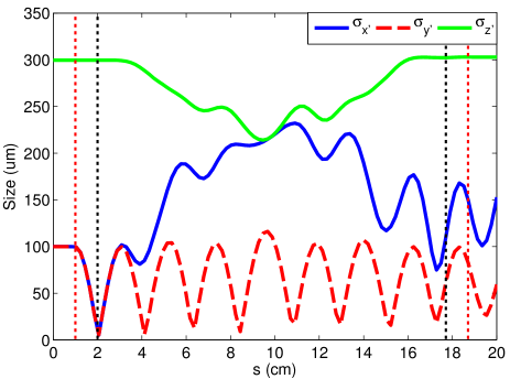
To test the particle deflection, we imported the 3D field map in GPT. The reference electron beam, consisting of macro-particles, is assumed to be injected from the left of Fig. 2 at . The simulated macro-particle trajectories are reported in Fig. 2. An initial (final) drift of 1 (2) cm is considered upstream (downstream) the capillary channel. The red (black) dotted lines show the overall path (without) including the two straight sections. The plot highlights that all the particles are properly bent and follow the curved path along the capillary. The beam envelopes are shown in Fig. 3. Here we refer to the envelopes , i.e. the ones calculated in the beam co-moving system . The relative position of the beam along its path is denoted by the longitudinal coordinate . One can see that the beam undergoes several betatron oscillations during its motion. These are evident by looking at the evolution of since such a plane is not affected by the deflection. Regarding the envelope, it exactly resembles up to the end of the straight capillary section (approximately at cm), then it starts to follows a different behavior on the plane of deflection.
An interesting feature pointed out by Fig. 3 is the evolution of the bunch length . What comes out is that such a quantity is effectively preserved (within of its initial value) at the end of the bending, thus no elongation (or longitudinal dispersion) of the bunch is observed as in the case of conventional bending magnets. It is due to the fact that, regardless of their energy, all the particles follow approximately the same path. Indeed, by considering that the focusing provided by the azimuthal magnetic field grows with radial distance from the capillary axis, larger (lower) is the particle energy larger (lower) would be the offset with respect to the reference path since . As a consequence a stronger (weaker) kick is produced and the resulting trajectories are almost independent on the particle energy.
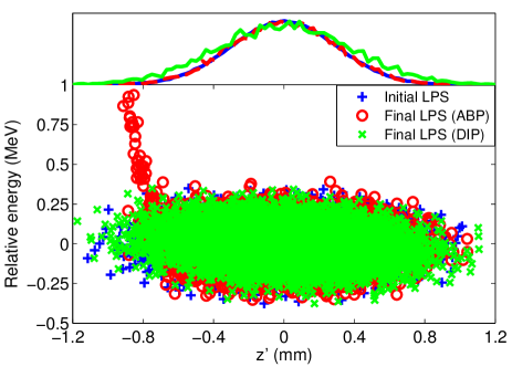
Fig. 4 compares the initial () and final () beam longitudinal phase space (LPS) computed by Architect. At the end of the ABP a small fraction (less than ) of particles in the tail is weakly accelerated by the induced plasma wakefield but the main core of the bunch actually remains unaffected and the overall elongation is of the order of . In the same plot we have also reported the resulting LPS at the exit of a conventional bending dipole (), modeled as a sector magnet with same radius of curvature and gap equal to . In this case the bunch acquires an energy chirp and its elongation is more pronounced (about ).
A parametric study of the main features of a possible ABP device is summarized in Fig. 5. The effectiveness in preserving the length of even ultra-short bunches (down to or, equivalently, 10 fs) is shown in Fig. 5(a) for several values of the bunch spot size at the ABP entrance. One can see that such a quantity is better preserved for small aspect ratio beams, i.e. when . A similar study is reported in Fig. 5(b) where we evaluated that also for very large energy spreads (up to ) the elongation is contained within only . The same plot highlights that, for a conventional bending dipole, the same values of energy spread would result in an overall elongation approximately 200 times larger. The ability to guide the beam for different current discharges flowing through the capillary is shown in Fig. 5(c). One can see that for the reference 100 MeV beam a minimum current kA is needed to properly bend all the particles. At lower values the guiding is inefficient and a larger fraction of particles is lost during the transport. On the contrary, at larger currents the guiding is always guaranteed since the resulting magnetic field is large enough to keep all the particles close to the reference trajectory. Finally, in Fig. 5(d) we have evaluated the resulting increase of the beam emittance as a function of the spot size at the capillary entrance. It results that the beam emittance is preserved when , which ensures that the magnetic field (as the one calculated in Fig. 2) is almost linear along the bunch radial profile. For the reference beam, instead, we find a dramatic emittance degradation (up to ) due to its large initial spot size. The best scenario is obtained when the beam is matched with the focusing channel. By assuming a linear focusing force (with ) acting at distance from the axis, the beam envelope equation is
| (1) |
where is the normalized lens focusing strength, the relativistic Lorentz factor and the electron rest mass. The equilibrium solution is associated to a betatron oscillation of amplitude and, thus, to a matched spot size equal to for the beam parameters described so far. For such a value the emittance minimum in Fig. 5(d) is obtained.
The ABP deflection capability can be scaled to even higher beam energies (and/or larger deflection angles) by changing its main parameters (radius of curvature, discharge current and capillary radius). Here we have demonstrated how to obtain the most compact structure able to bend a 100 MeV electron beam. For other cases, e.g. when dealing with larger energies, the radius of curvature has to be increased (since ) by employing longer capillaries and avoiding the use of too large discharge currents that can induce plasma pinch and other nonlinear effects.
In conclusion, we have presented a new device based on a capillary-discharge waveguide able to deflect particles at large angles. The theoretical treatment is discussed and supported by numerical simulations showing that the guiding, under certain conditions, preserves both the beam emittance and longitudinal phase space. The latter feature, in particular, would be particularly useful in accelerator facilities. If the beam has to be translated in a different beamline, a system consisting of (at least two) consecutive bending magnets separated by dispersion-matching focusing optics (e.g. quadrupoles and sextupoles) has to be adopted to preserve (or compress) the bunch duration England et al. (2005); Pompili et al. (2016). On the contrary, by means of the ABP even ultra-short beams can be transported without requiring additional optics. We have also demonstrated its capability in guiding particle beams with large energy spread as, for instance, the ones coming from plasma-based accelerators Faure et al. (2004); Geddes et al. (2004); Litos et al. (2014). In this case the transport up to a specific location represents a tricky task to accomplish if conventional magnetic optics (strongly affected by chromatic effects) is employed. With the ABP, instead, the overall elongation would be contained within only few percents. If compared to the state of the art of current technology, based on superconducting magnets operating at cryogenic temperatures, its practical implementation would be simpler and more affordable in terms of costs. The ABP might thus represent an affordable solution to develop more compact beamlines and, in general, to bend and guide charged particle beams.
Acknowledgements.
This work has been partially supported by the EU Commission in the Seventh Framework Program, Grant Agreement 312453-EuCARD-2, the European Union Horizon 2020 research and innovation program, Grant Agreement No. 653782 (EuPRAXIA), and the Italian Research Minister in the framework of FIRB - Fondo per gli Investimenti della Ricerca di Base, Project nr. RBFR12NK5K.References
- Reiser (2008) M. Reiser, Theory and design of charged particle beams (John Wiley & Sons, 2008).
- Bryant and Johnsen (2005) P. J. Bryant and K. Johnsen, The principles of circular accelerators and storage rings (Cambridge University Press, 2005).
- Leemann et al. (2009) S. Leemann, Å. Andersson, M. Eriksson, L.-J. Lindgren, E. Wallén, J. Bengtsson, and A. Streun, Physical Review Special Topics-Accelerators and Beams 12, 120701 (2009).
- Sokolov and Ternov (1966) A. A. Sokolov and I. M. Ternov, Akademia Nauk SSSR, Moskovskoie Obshchestvo Ispytatelei prirody. Sektsia Fiziki. Sinkhrotron Radiation, Nauka Eds., Moscow, 1966 (Russian title: Sinkhrotronnoie izluchenie), 228 pp. (1966).
- Helliwell (1998) J. R. Helliwell, Nature Structural & Molecular Biology 5, 614 (1998).
- Brown and Sturchio (2002) G. E. Brown and N. C. Sturchio, Reviews in Mineralogy and Geochemistry 49, 1 (2002).
- Weik et al. (2000) M. Weik, R. B. Ravelli, G. Kryger, S. McSweeney, M. L. Raves, M. Harel, P. Gros, I. Silman, J. Kroon, and J. L. Sussman, Proceedings of the National Academy of Sciences 97, 623 (2000).
- Lewis (1997) R. Lewis, Physics in medicine and biology 42, 1213 (1997).
- Suortti and Thomlinson (2003) P. Suortti and W. Thomlinson, Physics in medicine and biology 48, R1 (2003).
- Gemmell (1974) D. S. Gemmell, Reviews of Modern Physics 46, 129 (1974).
- Dabagov et al. (2015) S. B. Dabagov, A. V. Dik, and E. N. Frolov, Physical Review Special Topics-Accelerators and Beams 18, 064002 (2015).
- Tomita and Murakami (2003) M. Tomita and M. Murakami, Nature 421, 517 (2003).
- Todesco et al. (2004) E. Todesco, B. Bellesia, L. Bottura, A. Devred, V. Remondino, S. Pauletta, S. Sanfilippo, W. Scandale, C. Vollinger, and E. Wildner, IEEE transactions on applied superconductivity 14, 177 (2004).
- Evans and Bryant (2008) L. Evans and P. Bryant, Journal of instrumentation 3, S08001 (2008).
- Tajima and Dawson (1979) T. Tajima and J. M. Dawson, Physical Review Letters 43, 267 (1979).
- Rocca et al. (1993) J. Rocca, O. Cortazar, B. Szapiro, K. Floyd, and F. Tomasel, Physical Review E 47, 1299 (1993).
- Rocca et al. (1996) J. J. Rocca, D. Clark, J. Chilla, and V. Shlyaptsev, Physical review letters 77, 1476 (1996).
- Tomasel et al. (1997) F. Tomasel, J. Rocca, V. Shlyaptsev, and C. Macchietto, Physical Review A 55, 1437 (1997).
- Hosokai et al. (2000) T. Hosokai, M. Kando, H. Dewa, H. Kotaki, S. Kondo, N. Hasegawa, K. Nakajima, and K. Horioka, Optics Letters 25, 10 (2000).
- Leemans et al. (2006) W. Leemans, B. Nagler, A. Gonsalves, C. Tóth, K. Nakamura, C. Geddes, E. Esarey, C. Schroeder, and S. Hooker, Nature physics 2, 696 (2006).
- Blumenfeld et al. (2007) I. Blumenfeld, C. E. Clayton, F.-J. Decker, M. J. Hogan, C. Huang, R. Ischebeck, R. Iverson, C. Joshi, T. Katsouleas, N. Kirby, W. Lu, K. A. Marsh, W. B. Mori, P. Muggli, E. Oz, R. H. Siemann, D. Walz, and M. Zhou, Nature 445, 741 (2007).
- Su et al. (1990) J. Su, T. Katsouleas, J. Dawson, and R. Fedele, Physical Review A 41, 3321 (1990).
- Boggasch et al. (1992) E. Boggasch, A. Tauschwitz, H. Wahl, K.-G. Dietrich, D. Hoffmann, W. Laux, M. Stetter, and R. Tkotz, Applied physics letters 60, 2475 (1992).
- Hairapetian et al. (1994) G. Hairapetian, P. Davis, C. Clayton, C. Joshi, S. Hartman, C. Pellegrini, and T. Katsouleas, Physical review letters 72, 2403 (1994).
- Van Tilborg et al. (2015) J. Van Tilborg, S. Steinke, C. Geddes, N. Matlis, B. Shaw, A. Gonsalves, J. Huijts, K. Nakamura, J. Daniels, C. Schroeder, et al., Physical review letters 115, 184802 (2015).
- Pompili et al. (2017) R. Pompili, M. Anania, M. Bellaveglia, A. Biagioni, S. Bini, F. Bisesto, E. Brentegani, G. Castorina, E. Chiadroni, A. Cianchi, et al., Applied Physics Letters 110, 104101 (2017).
- Butler et al. (2002) A. Butler, D. Spence, and S. M. Hooker, Physical Review Letters 89, 185003 (2002).
- Spence et al. (2003) D. Spence, A. Butler, and S. Hooker, JOSA B 20, 138 (2003).
- Ehrlich et al. (1996) Y. Ehrlich, C. Cohen, A. Zigler, J. Krall, P. Sprangle, and E. Esarey, Physical review letters 77, 4186 (1996).
- Reitsma and Jaroszynski (2008) A. Reitsma and D. Jaroszynski, IEEE Transactions on Plasma Science 36, 1738 (2008).
- Note (1) All the quantities are quoted as root mean square (rms).
- De Loos and Van der Geer (1996) M. De Loos and S. Van der Geer, in 5th European Particle Accelerator Conference (1996) p. 1241.
- Marocchino et al. (2016) A. Marocchino, F. Massimo, A. Rossi, E. Chiadroni, and M. Ferrario, Nuclear Instruments and Methods in Physics Research Section A: Accelerators, Spectrometers, Detectors and Associated Equipment 829, 386 (2016).
- Bobrova et al. (2001) N. Bobrova, A. Esaulov, J.-I. Sakai, P. Sasorov, D. Spence, A. Butler, S. Hooker, and S. Bulanov, Physical Review E 65, 016407 (2001).
- Bennett (1955) W. H. Bennett, Physical Review 98, 1584 (1955).
- Vrba and Vrbová (2000) P. Vrba and M. Vrbová, Contributions to Plasma Physics 40, 581 (2000).
- Studio (2008) M. Studio, Bad Nuheimer Str 19, 64289 (2008).
- England et al. (2005) R. England, J. Rosenzweig, G. Andonian, P. Musumeci, G. Travish, and R. Yoder, Physical Review Special Topics-Accelerators and Beams 8, 012801 (2005).
- Pompili et al. (2016) R. Pompili, M. P. Anania, M. Bellaveglia, A. Biagioni, G. Castorina, E. Chiadroni, A. Cianchi, M. Croia, D. D. Giovenale, M. Ferrario, F. Filippi, A. Gallo, G. Gatti, F. Giorgianni, A. Giribono, W. Li, S. Lupi, A. Mostacci, M. Petrarca, L. Piersanti, G. D. Pirro, S. Romeo, J. Scifo, V. Shpakov, C. Vaccarezza, and F. Villa, New Journal of Physics 18, 083033 (2016).
- Faure et al. (2004) J. Faure, Y. Glinec, A. Pukhov, S. Kiselev, et al., Nature 431, 541 (2004).
- Geddes et al. (2004) C. Geddes, C. Toth, J. Van Tilborg, E. Esarey, et al., Nature 431, 538 (2004).
- Litos et al. (2014) M. Litos, E. Adli, W. An, C. Clarke, C. Clayton, S. Corde, J. Delahaye, R. England, A. Fisher, J. Frederico, et al., Nature 515, 92 (2014).