11email: boqunwg@ucmail.uc.edu
Belle II iTOP Optics: Design, Construction and Performance
Abstract
The imaging-Time-of-Propogation (iTOP) counter is a new type of ring-imaging Cherenkov counter developed for particle identification at the Belle II experiment. It consists of 16 modules arranged azimuthally around the beam line. Each module consists of one mirror, one prism and two quartz bar radiators. Here we describe the design, acceptance test, alignment, gluing and assembly of the optical components. All iTOP modules have been successfully assembled and installed in the Belle II detector by the middle of 2016. After installation, laser and cosmic ray data have been taken to test the performance of the modules. First results from these tests are presented.
Keywords:
Cherenkov detector, iTOP counter, Belle II1 Introduction
The Belle II [1]/SuperKEKB [2] experiment is an upgrade of the Belle/KEKB experiment for searching for New Physics (NP), which is physics beyond the Standard Model (SM). The upgraded detector is planning to take of collision data, with a design luminosity of . This is about 40 times larger than the KEKB collider. To achieve such high luminosity, the so-called nano-beam technology [3] is used to squeeze the beam bunches significantly.
Many sub-detectors of Belle will be upgraded for Belle II. This includes the newly designed iTOP (imaging-Time-Of-Propogation) counter [4, 5, 6, 7], which is the particle identification counter in the barrel region. It consists of a 2.7 m long quartz optics for the radiation and propogation of the Cherenkov light, an array of micro-channel-plate photo-multiplier tubes (MCP-PMT) [8] for photon detection, and wave-sampling front-end readout electronics [9, 10]. This article describes the design, construction and performance of the optics for the iTOP counter.
2 Detector Design
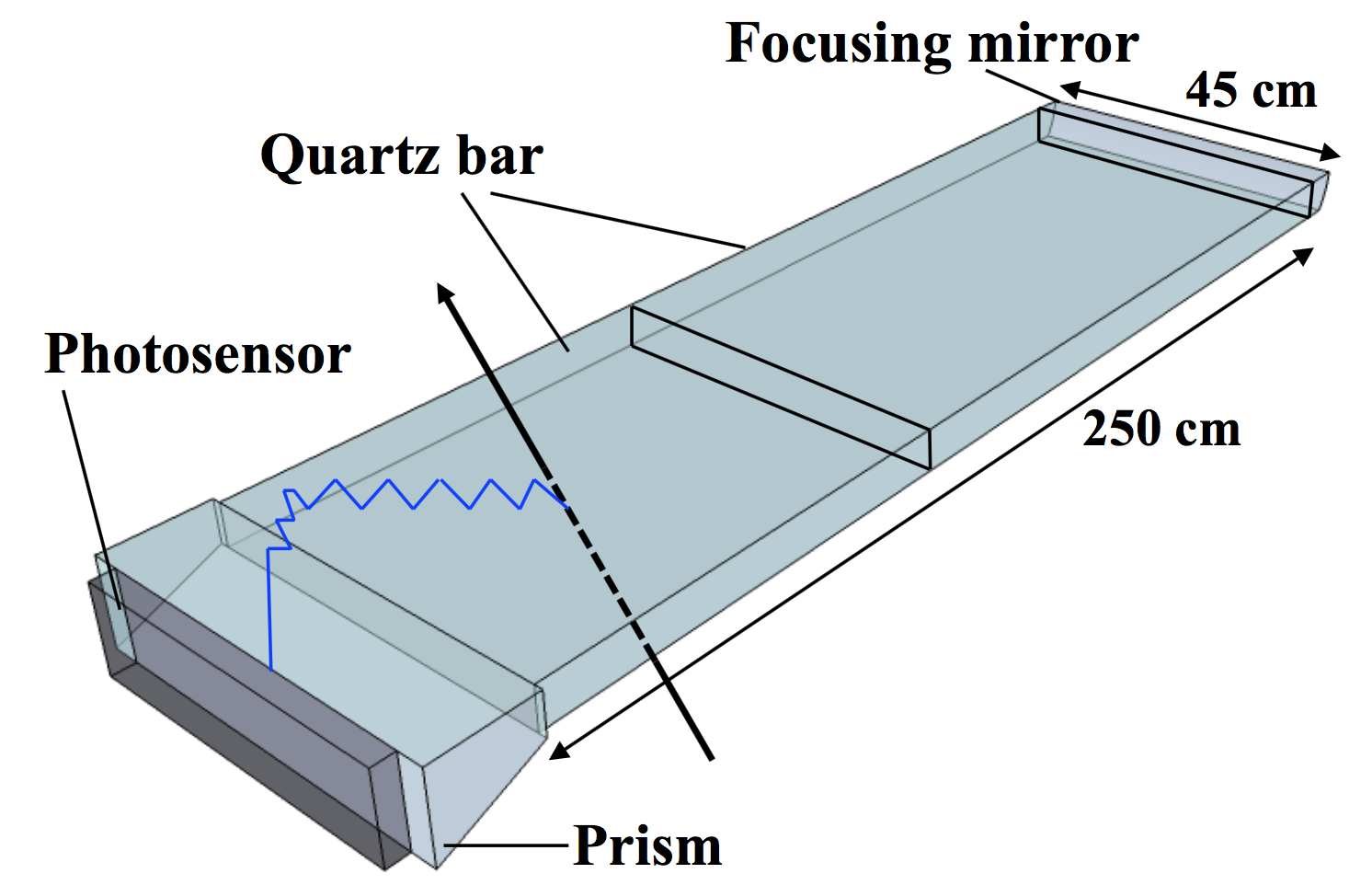
As shown in Fig. 2, one iTOP module consists of two bars with the dimension as 1250 450 20 mm. At one end of the bars is the reflection mirror with spherical surface. At the other end is the expansion block called prism. All optics components are made of Corning 7980 synthetic fused silica, which has a high purity and no striae inside.
When a charged track goes through the quartz radiator, it emits Cherenkov photons. The Cherenkov angle depends on the mass of the particle for a given momentum, the latter is measured by the central drift chamber (CDC). The photons are reflected by the bar surfaces and the reflection mirror, then collected by the MCP-PMTs at the prism end. The resolution of the photon sensors and the front end electronics are required to be better than 50 ps, which is needed to distinguish the time of propogation difference between Cherenkov photons from and tracks.
3 Module Construction
The construction of the real iTOP module was started in the end of 2014 and all 17 modules, including one spare, were finished by April 2016. After testing with laser and cosmic ray, these modules were installed on Belle II detector by May 2016.
3.1 QA of Quartz Optics
To achieve the high K/ separation capability of the iTOP counter, the optics need to have very high quality. The Cherenkov photons can reflect hundreds of times inside the quartz radiator, so the surfaces of the quartz bars need to be highly polished. The requirement for surface roughness is 5 År.m.s., and for flatness the requirement is 6.3 . For all 34 bars needed, 30 were produced by Zygo Corporation (USA) and 4 were produced by Okamoto Optics Works (Japan).
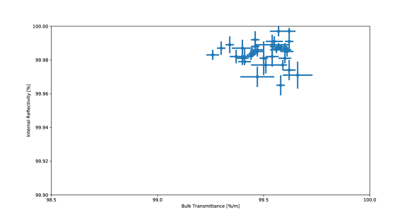
After receiving the quartz bars from the vendors, they were mounted on the measurement stage for the QA tests. By injecting laser beam perpendicular to one surface of the bar or have a angle relative to it, we can measure the bulk transmittance and internal reflectivity of the quartz bar by measuring the laser intensity before and after it went through the bar. The requirements for bulk transmittance and internal reflectivity were 98.5 %/m and 99.9 %, respectively. As shown in Fig. 2, all received quartz bars met the requirements.
For the QA of the other optics, the most important tests were the angle of the tilted surface of the prism and the radius of the mirror’s spherical surface. They were measured by injecting laser to the optics and measure the laser direction after it went through or reflected by the optics. All optics met the requirements.
3.2 Gluing and Assembly
After the QA process was finished and all the quartz optics passed the requirements, two quartz bars, one prism and one mirror were mounted on a gluing stage for precision alignment and gluing.
Two laser displacement sensors and an autocollimator were used for the alignment. Laser displacement sensor measures the distance to the surface. It was used to align the position, both horizontal and vertical, of two optics’ surfaces. Autocollimator injects laser to a mirror which is mounted on the surface of the optics, and by measuring the angle of the reflected laser relative to the original one to get the angle information. It is used to align the angle between two optics’ surfaces.
After the alignment, the optics were moved together with a 50 100 gap. The joints between optics were taped by using Teflon tape to make a “dam” to prevent the epoxy from flowing outside. The epoxy used for gluing was EPOTEK 301-2. It consists of two parts, which needs to be mixed before gluing. The mixture was centrifuged to remove the air bubbles inside. Then the adhesive was applied from a syringe to the glue joint by using high pressure dry air. After applying, it took 3 4 days to be fully cured.
When the curing process was finished, the excessive glue was removed using Acetone. The alignment may change after the curing, so it needed to be measured again. The achieved horizontal and vertical angle between the two optics near the glue joint was within 40 arcsec and 20 arcsec, respectively.
The completed iTOP optics was moved into a Quartz Bar Box (QBB). The QBB is a light-tight supporting structure made of aluminum honeycomb plates. It has high rigidity with light material. The optics was supported on by PEEK buttons that were glued to the inner surfaces of QBB.
When the QBB assembly was completed, the MCP-PMT modules with front-end electronics were installed at the prism end of the module.
3.3 Installation
After the iTOP module assembly was completed, it was transferred by truck to the experimental hall for installation. Each module was installed by using movable stages. A module was mounted on a guide pipe, which was supported by the stages, so it was able to move and rotate around the guide pipe. The module deflection during the installation process was monitored by deflection sensors, and it was required to be less than 0.5 mm. The installation of all the modules was completed in May, 2016. More details can be found in Ref. [11].
4 Performance with Cosmic Ray
After installation, the cosmic ray data was taken to validate detector performance with and without the magnetic field. Six cosmic ray triggers were prepared, with each consisted of a plastic scintilltor bar. Their positions along the beam axis were the same with the collision point and their positions in x-y plane can be changed as needed.
For the performance test with cosmic ray, the tracking information was not available. The number of observed photon hits for each iTOP module was compared between data and MC simulation. For no magnetic field condition, the number of photon hits for data was consistent with MC simulation within 15%. For the 1.5T magnetic filed condition, the discrepancy is at 20 - 30 % level. There are many reasons for this, including the angle and momentum distributions in the cosmic ray muon flux, the hit identification efficiency of MCP-PMTs, etc. More detailed studies are planned by combining tracking information from the CDC detector.
5 Summary
The iTOP counter is a novel particle identification device in the barrel region for Belle II detector. In this article we described the design, construction and performance of the iTOP counter. The last iTOP module has been finished and installed in May 2016, and the Belle II detector has been moved to the beam line in April 2017. Currently the global cosmic ray data taking is on going, for the purpose of testing, calibration and integration of the sub-detectors including iTOP counters.
This research is supported under DOE Award DE-SC0011784. I’d like to thank the organizers of the TIPP 2017 conference for allowing me to give this talk.
References
- [1] T. Abe, et al., KEK-REPORT-2010-1, 2010.
- [2] Y. Ohnishi, et al., Prog. Theor. Exp. Phys. (2013) 2013 (3): 03A011.
- [3] P. Raimondi, talk given at the 2nd SuperB workshop, Frascati, http://www.lnf.infn.it/conference/superb06/talks/raimondi1.ppt, 2006.
- [4] T. Ohshima, ICFA Instrumentation Bulletin 20 (2000) 10.
- [5] M. Akatsu, et al., Nucl. Instr. and Meth. A 440 (2000) 124.
- [6] T. Ohshima, Nucl. Instr. and Meth. A 453 (2000) 331.
- [7] Y. Enari, et al., Nucl. Instr. and Meth. A 494 (2002) 430.
- [8] K. Matsuoka, For the Belle II PID group, PoS(TIPP2014)093.
- [9] Andrew M 2012 IEEE Realtime Conf. Rec. 1–5.
- [10] Andrew M 2014 PoS (TIPP2014) 171.
- [11] K. Suzuki et. al., Nucl. Instrum. Methods A in press, DOI: 10.1016/j.nima.2017.03.052.