Magnetic Skyrmionic Polarons
Abstract
We study a two-dimensional electron gas exchanged-coupled to a system of classical magnetic ions. For large Rashba spin-orbit coupling a single electron can become self-trapped in a skyrmion spin texture self-induced in the magnetic ions system. This new quasiparticle carries electrical and topological charge as well as a large spin, and we named it as magnetic skyrmionic polaron. We study the range of parameters; temperature, exchange coupling, Rashba coupling and magnetic field, for which the magnetic skyrmionic polaron is the fundamental state in the system. The dynamics of this quasiparticle is studied using the collective coordinate approximation, and we obtain that in presence of an electric field the new quasiparticle shows, because the chirality of the skyrmion, a Hall effect. Finally we argue that the magnetic skyrmionic polarons can be found in large Rashba spin-orbit coupling semiconductors as GeMnTe.
Keywords: Magnetic Skyrmions, Polarons, Magnetic Semiconductors
In 1962 Skyrme introduced a model where particles as photons and neutrons show up as topological defects of fields of mesons1. These particles were named skyrmions and also appear as topological excitations in the continuum limit of the two-dimensional (2D) ferromagnetic Heisenberg model; the celebrated non-linear sigma model (NLSM)2, . Here is the magnetization unit vector and is the spin stiffness. The NLSM is scale invariant and the energy of the skyrmion, , does not depend on its size or on a global spin rotation3. By extension, the term skyrmion is also used to name topological excitations of two component scalar field in 2D systems. In these cases extra terms added to the NLSM make the energy, shape and size of the skyrmions depend on the details of the Hamiltonian. Apart from nuclear physics4 skyrmions appear in many brands of modern physics4 as two-dimensional electron gas in the quantum Hall regime5, 6, liquid crystals7, Bose-Einstein condensates8 and in the last years the study of skyrmions has convulsed the research of magnetic materials9, 10, 11, 12, 13, 14, 15, 16.
In 2D ferromagnetic systems, a magnetic skyrmion describes a localized spin texture, where in going from the core to the perimeter of the particle, the orientation of the spin full wraps the unit sphere. The topology of the skyrmion is characterized by a nonzero topological charge,
| (1) |
that indicates the number of times the unit sphere is wrapped by the magnetization , when this covers the full real space. The topological character of the skyrmions protects them from continuous deformation into the uniform and conventional ferromagnetic state, conferring them a long lifetime. This protection, in addition with the experimental fact that skyrmions can be driven by low electrical current densities17, makes them very promising particles for spintronic devices18, 19. Different mechanisms15 as long-ranged magnetic dipolar interactions20, frustrated exchange interactions21 or four-spin exchange mechanism22, can produce stable skyrmions in magnetic systems. Very interesting are the skyrmions that appear in non-centrosymmetric magnets, where the competition between an antisymmetric Dzyaloshinskii-Moriya (DM) interaction23, 24 and a symmetric exchange coupling can generate, in presence of an external magnetic field, skyrmions with size ranging from 5 to 100. The origin of the DMI is the lack of inversion symmetry in lattices or at the interface of magnetic films. In ultrathin magnetic films the DMI appear as the exchange coupling between two atomic spins mediated by a heavy atom with a large spin-orbit coupling (SOC)25, 26. The DMI between classical spins can also occurs as a modified Ruderman-Kittel-Kasuya-Yosida 27, 28, 29 interaction, where the intermediary 2D electron gas has a Rashba SOC30, 31, 32. Double exchange magnetic metals33 with strong SOC may also generate DM interaction between the magnetic ions 32, 34.
In diluted magnetic semiconductors a single electron is able to create a ferromagnetic collective ground state of a large number of magnetic impurities35, 36. Also there is evidence37, 38, 39 that a single electron can be self-trapped in a magnetic polaron. The question then arises is if a single electron with Rashba spin-orbit coupling can be self-trapped in a spin texture induced in a coupled system of magnetic ions. By combining analytical calculations and numerical computation, we find compelling evidence that the Rashba spin orbit coupling makes that a single electron creates and becomes self trapped in a skyrmion spin texture. We name this quasiparticle as magnetic skyrmionic polaron.
The Hamiltonian for electrons moving in the conduction band of a 2D semiconductor in the presence of a unit vector magnetization is
| (2) |
where , and are the Pauli matrices and is the exchange coupling constant that we consider positive. In the Hamiltonian we also have included a Zeeman field, , acting on the magnetic impurities. In Eq.2 is the effective mass and the Rashba SOC.
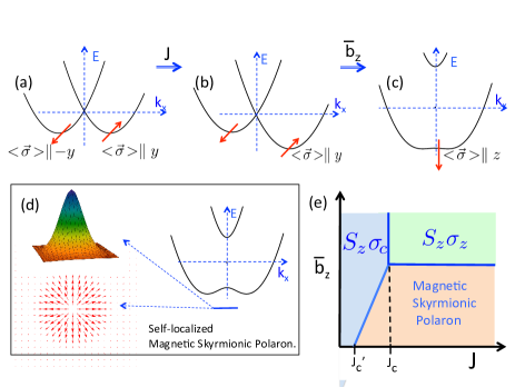
Different trivial uniform states can surge from the coupling between the electron spin and the magnetic impurities. For ==0, the energy of the electron is = with = and the minimum occurs at the ring defined by =. Because of the SOC, the spin of a state with momentum , points in the direction = . For =0 and finite coupling between the electron spin and the magnetic ions, , a single electron selects an in-plane magnetic orientation for the system of magnetic ions. We call this phase , Figure 1(b). For 0 and , polarizes along the -direction and the electron spin orientation gets a component along the -direction, canted phase , until that for >=, both the electron spin and become polarized in the -direction in a phase we call , Figure 1(c). In this work we study the transition, as function of , between the and the phases and show that the electron can be self-trapped by a skyrmion induced in the coupled magnetic ion system, forming a magnetic skyrmionic polaron, Figure 1(d).
Effective spinless Hamiltonian. Here we consider a single electron en presence of a =1 skyrmion of the form,
| (3) |
where is the polar angle and is a continuous function satisfying = and =0, and we minimize the energy of the system withs respect the size of the skyrmion. We use an unitary transformation of the Hamiltonian which makes the spin quantization direction parallel to the direction of the magnetization 40, 41, 42, i.e. = with =, being = and =. We are interested in the zero density limit in which is the largest energy in the system and we neglect electrons with spin locally antiparallel to the magnetization . In this approximation we obtain the following Hamiltonian for spinless electrons,
| (4) | |||||
The first two terms in contain the coupling between the electron and the gauge vector potential and electrostatic potential generated by the spatial variation of the order parameter , respectively. The third has its origin in the rotation of the Rashba term. The vector potential describes a topological magnetic field = -=, that is proportional to the density of topological charge in the spin texture. The skyrmion profile is well modeled43 as = for and =0 for , that describes a smooth radial spin texture inside the skyrmion radius . For this profile, =, for < and zero elsewhere, then the second and third term of describe a quantum dot of radius and potential . The average topological magnetic field takes a value = that implies a magnetic length = smaller that than the dot radius and therefore an electron located on the skyrmion should have a zero point motion energy . Adding all contributions the energy of the system is,
| (5) |
Minimizing this equation with respect the radius of the skyrmion, we obtain that for small values of the Zeeman field, there is always a negative energy solution that corresponds to the self trapping of the electron in a self-induced skyrmion spin texture. At =0 the radius of the skyrmion is , and decreases as increases.
We call this quasiparticle a magnetic skyrmionic polaron. This particle competes in energy with the non-topological states , and . A typical phase diagram is shown in in Figure 1(e). At large values of and all spins polarize in -direction and the ground state is , for large values of but moderate values of , the magnetic ions polarize in the -direction, but the electron spin is canted, phase . For large values of and moderate values of the electron self-traps in a magnetic skyrmionic polaron. At =0, the transition between the and the magnetic polaronic phase occurs at . The difference between - is the binding energy of the magnetic skyrmionic polaron at =0.
The results obtained from the effective spinless Hamiltonian Eq.4, provide a physical insight of how an electron can be self-trapped in a skyrmion. In the following we perform tight-binding calculations in order to check the validity of the previous conclusions and also for studying a wider range of values of the exchange coupling and obtain a more accurate description of the magnetic skyrmionic polarons. We consider a square lattice, first-neighbors hopping tight-binding Hamiltonian44,
| (6) | |||||
where creates an electron at site with spin , =, =, = is the electron spin operator, is the impurity spin normalized to unity and = ,being the lattice spacing. We consider a single electron in a supercell containing sites and use periodic boundary conditions, so that the density of charge in the system is . The Hamiltonian Eq.6 is solved self consistently in a process where after diagonalizing and obtaining the wave-function of the lowest energy state in presence of a spin texture, we recalculated the spin texture created by the expectation value of the electron spin operator and and then repeat the process until input and output coincide. Solving Eq.6, we obtain the electron energy and wave-function, as well that the orientation of the magnetic ions . For a given spin configuration the topological charge is obtained by following the prescription of Berg and Lusher45. We divide each basic unit square of the lattice into two triangles. The three spins at the corners of each triangle define a signed area on the unit sphere , and the topological charge in the supecell is given by =, where the sum runs over all triangles in the system.
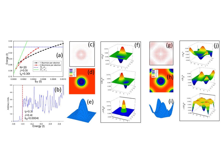
By starting the self-consistent procedure with seeds corresponding to different spin textures, we obtain solutions with different topological charge in the unit cell. In the tight-binding calculation we do not impose any constrain to the size and shape of the skyrmions. In Figure 2(a) we plot the energy per unit cell of different states for the case =0.3, =0.5 and =20, as function of the Zeeman field . For these large values of , the relevant uniform non-topological phases are , with energy -4-- that is the ground state for large values of and with energy -4-- that is the relevant phase for . We see in Figure 2(a) that there is a range of Zeeman fields for which the low energy state corresponds to a =1 magnetic skyrmionic polaron. This is evident in Figure 2(c)-(d) where we plot the and the -component of the ion spins for =0.5, =0.3 and =0.0005. Clearly, there is an isolated skyrmion located at the center of the unit cell. The coupling between the electron and the magnetic ions is also reflected in the electron spin density shown in Figure 2(f), that shows the same symmetry and shape than the ions spin texture. The self-trapping of the electron by the skyrmion and the binding energy is also reflected in the electron density of states, Figure 2(b); below the bottom of the electron band, -4-, there appears a sharp peak containing exactly one electron and that corresponds to the magnetic skyrmionic polaron. In Figure 2(a) we notice that at very low Zeeman fields, the low energy phase corresponds to a topological charge =2 in the unit cell. This phase occurs because for small values of , the size of the skyrmion increases and skyrmions centered in neighbor unit cells overlap and interact, being energetically favorable for the system to creates a skyrmion crystal with two =1 skyrmions per unit cell, Figure 2(g)-(i), and a single electron per unit cell Figure 2(j).
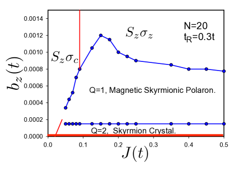
In Figure 3 we show a phase diagram versus , for =0.3t obtained in a supercell with =20. The main differences when comparing with the obtained in the effective spinless Hamiltonian, Figure 1(e) are, first there is a small but finite region of values of where the ground state is and second, by increasing in the transition from the state to the magnetic skyrmionic polaron phase, there appears a region where there are two skyrmions per electron, crystallizing in a square lattice. Both effects occur because of the small size of the unit cell, the energy associated with the polarization of the magnetic ions in the -direction is , and therefore as larger is , smaller is the region in the - parameter space where is the ground state. In the same way, as increases the overlap between magnetic skyrmionic polaron decreases and the Q=2 region disappears in the phase diagram.
Dynamics of magnetic skyrmionic polarons. The dynamics of the impurity spins, treated as classicals, is dictated by the Landau-Lifshitz equation46,
| (7) |
where <<1 is the phenomenological Gilbert damping constant and is the local effective field, written in energy units, that is derived form te Hamiltonian, . In the previous equation we have not included a current-induced torque because although the spin texture is charged it is placed in an insulator materials47, 48. Equation 7 describes both the deformation and the dynamics of the skyrmions. The excitation of the internal modes of the skyrmions have a finite frequency, that increases with the presence of an external magnetic filed and this justify the treatment of skyrmions as rigid particles49, that move across the sample without distortion. Therefore, the dynamics of skyrmions is defined by the position and velocity of its center of mass. The motion of the center of mass is obtained by integrating the Landau-Lifshitz equations following the method developed by Thiele50, 51, 52, and for a magnetic texture as that described in Eq.3 we obtain,
| (8) |
here is the magnetic moment per unit area in the magnetic system, =, = and is the so called generalized force acting on the skyrmion due to impurities, magnetic fields or boundary conditions15. Magnetic skyrmionic polarons are charged particles and therefore they also response to electromagnetic fields. In the case of an electric field =, the skyrmion acquires a velocity,
| (9) | |||||
| (10) |
The magnetic skyrmionic polaron steady velocity in the direction of the electric field is determined by the balance between electric field and damping. In the limit of vanishing damping the particle shows a Hall effect with = and =, that defines a mobility =, that for a density of magnetic moments of the order of takes values that implies drift velocities for applied electric fields =eV/m, comparable or larger to that of magnetic skyrmions driven by electric current53, 54. Large drift velocities have been also predict for skyrmions placed on top of topological insulators55.
We estimate the effect of the temperature on the existence of magnetic skyrmionic polarons in the mean field approximation. The effective magnetic filed acting on the normalized spin impurity is,
| (11) |
where us the expectation value of the electron spin operator at site . In the mean field approximation the free energy of classical spin is,
| (12) |
from which the expectation value of the spin impurity is56
| (13) |
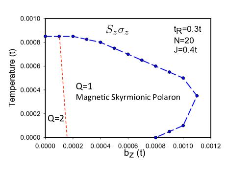
By solving self-consisting Eq.6, with the values of the ion spin replaced by , Eq.13, we obtain the temperature phase diagram for the occurrence of magnetic skyrmionic polarons. In this approximation we assume that the magnetic skyrmionic polaron binding energy os larger than the temperature and the only participating electron state is that with lowest energy. The main effect of temperature is the reduction of the expectation value of the classical spins, that results in an effective reduction of the Rashba spin orbit coupling in Eq.6. In Figure 4 we plot the phase diagram temperature- for the parameters =0.3, =0.4 and a unit cell . When increasing temperature the reduction of the effective Rashba coupling induces a transition from the skyrmionic phase to the phase. The reentrance of the phase at large values of reflects the maxima occuring in the - phase diagram, Eq.3.
In closing, in this paper we have shown, using analytical estimations and numerical calculations, that a single electron moving in a band with a strong Rashba spin-orbit coupling and coupled to magnetic ions can be self-trapped by forming a skyrmion spin texture. We have calculated the phase diagram for the existence of this magnetic skyrmionic polaron, as function of the exchange coupling, Rashba SOC, temperature and external magnetic field. Also, we have analyzed the dynamics of the skyrmionic polaron and found that in presence of an electric field, the skyrmion will show a Hall effect with a rather large mobility and drift velocity.
In this work we have studied a 2D semiconductor in the limit of very low electron density. For higher electron densities, a well-defined RKKY interaction between magnetic impurities should develop. In the presence of Rashba spin-orbit coupling, this interaction should induce effective exchange and DM interactions between the ion spins. In this high-density regime, a phase diagram with a helical, ferromagnetic and skyrmion crystal phases, as that presented in ref.32, is expected. In this high density regime, the skyrmions in the crystal phase should overlap strongly and the resulting electronic density should be slightly modulated with a small charge accumulation near the skyrmion core57.
The existence of magnetic skyrmionic polaron requires a semiconductor with a large Rashba SOC and a large exchange coupling between the electron spin and the magnetic ions. Recently it has been reported soft X-ray ARPES on epitaxially grown thin films of Ge1-xMnxTe58. For a concentration =5.4% of Mn, the measured band structure parameters are, =0.2, =3eVÅ, and =0.11eV, that correspond to the following tight-binding parameters, =0.53eV, =0.25eV and J=0.06eV obtained using a lattice constant Å59. From these numbers, and comparing with the results presented in Figure 2 and Figure 3 we conclude that it is possible that magnetic skyrmionic polarons appear in Ge1-xMnxTe at very low densities and temperatures lower than 10K. For a concentration of Mn ions of 5% the magnetic skyrmionic polarons will be present up to rather large magnetic fields, 20T. Recently obtained quasi two-dimensional ferromagnetic materials60, 61, 62, are expected to have a strong Rashba spin orbit coupling and therefore are also good candidates to host magnetic skyrmionic polarons.
Author acknowledges H.A.Fertig for helpful discussions. This work has been partially supported by the Spanish MINECO Grant No. FIS2015–64654-P.
References
- Skyrme 1962 Skyrme, T. H. R. Nuclear Physics 1962, 31, 556–569
- Belavin et al. 1984 Belavin, A. A.; Polyakov, A. M.; Zamolodchikov, A. B. Nucl. Phys. 1984, B241, 333–380
- A.Rajaraman 1987 A.Rajaraman, An Introduction to Solitons and Instantons in Quantum Field Theory; Elsevier, 1987
- G.E.Brown and Rho 2010 G.E.Brown,, Rho, M., Eds. The Multifaceted Skyrmion; World Scientific, 2010
- Fertig et al. 1994 Fertig, H. A.; Brey, L.; Côté, R.; MacDonald, A. H. Physical Review B 1994, 50, 11018–11021
- Brey et al. 1995 Brey, L.; Fertig, H. A.; Côté, R.; MacDonald, A. H. Physical Review Letters 1995, 75, 2562–2565
- Fukuda and Žumer 2011 Fukuda, J.-i.; Žumer, S. Nature Communications 2011, 2, 246 EP –
- Al Khawaja and Stoof 2001 Al Khawaja, U.; Stoof, H. Nature 2001, 411, 918–920
- Roszler et al. 2006 Roszler, U. K.; Bogdanov, A. N.; Pfleiderer, C. Nature 2006, 442, 797–801
- Mühlbauer et al. 2009 Mühlbauer, S.; Binz, B.; Jonietz, F.; Pfleiderer, C.; Rosch, A.; Neubauer, A.; Georgii, R.; Böni, P. Science 2009, 323, 915
- Yu et al. 2010 Yu, X. Z.; Onose, Y.; Kanazawa, N.; Park, J. H.; Han, J. H.; Matsui, Y.; Nagaosa, N.; Tokura, Y. Nature 2010, 465, 901–904
- Duine 2013 Duine, R. Nat Nano 2013, 8, 800–802
- Fert et al. 2013 Fert, A.; Cros, V.; Sampaio, J. Nat Nano 2013, 8, 152–156
- J. et al. 2013 J., S.; V., C.; S., R.; A., T.; A., F. Nat Nano 2013, 8, 839–844
- Nagaosa and Tokura 2013 Nagaosa, N.; Tokura, Y. Nat Nano 2013, 8, 899–911
- Rosch 2017 Rosch, A. Nat Nano 2017, 12, 103–104
- Jonietz et al. 2010 Jonietz, F.; Mühlbauer, S.; Pfleiderer, C.; Neubauer, A.; Münzer, W.; Bauer, A.; Adams, T.; Georgii, R.; Böni, P.; Duine, R. A.; Everschor, K.; Garst, M.; Rosch, A. Science 2010, 330, 1648
- Parkin et al. 2008 Parkin, S. S. P.; Hayashi, M.; Thomas, L. Science 2008, 320, 190
- Parkin and Yang 2015 Parkin, S.; Yang, S.-H. Nat Nano 2015, 10, 195–198
- Lin et al. 1973 Lin, Y. S.; Grundy, P. J.; Giess, E. A. Applied Physics Letters 1973, 23, 485–487
- Okubo et al. 2012 Okubo, T.; Chung, S.; Kawamura, H. Physical Review Letters 2012, 108, 017206–
- Heinze et al. 2011 Heinze, S.; von Bergmann, K.; Menzel, M.; Brede, J.; Kubetzka, A.; Wiesendanger, R.; Bihlmayer, G.; Blugel, S. Nat Phys 2011, 7, 713–718
- Dzyaloshinsky 1958 Dzyaloshinsky, I. Journal of Physics and Chemistry of Solids 1958, 4, 241–255
- Moriya 1960 Moriya, T. Physical Review 1960, 120, 91–98
- Fert and Levy 1980 Fert, A.; Levy, P. M. Physical Review Letters 1980, 44, 1538–1541
- A.Fert 1980 A.Fert, Mater. Sci. Forum 1980, 59-60, 439–480
- Ruderman and Kittel 1954 Ruderman, M. A.; Kittel, C. Physical Review 1954, 96, 99–102
- Kasuya 1956 Kasuya, T. Progress of Theoretical Physics 1956, 16, 45–57
- Yosida 1957 Yosida, K. Physical Review 1957, 106, 893–898
- Imamura et al. 2004 Imamura, H.; Bruno, P.; Utsumi, Y. Physical Review B 2004, 69, 121303–
- Kim et al. 2013 Kim, K.-W.; Lee, H.-W.; Lee, K.-J.; Stiles, M. D. Physical Review Letters 2013, 111, 216601–
- Banerjee et al. 2014 Banerjee, S.; Rowland, J.; Erten, O.; Randeria, M. Physical Review X 2014, 4, 031045–
- de Gennes 1960 de Gennes, P. G. Physical Review 1960, 118, 141–154
- Calderón and Brey 2001 Calderón, M. J.; Brey, L. Physical Review B 2001, 63, 054421–
- Fernández-Rossier and Brey 2004 Fernández-Rossier, J.; Brey, L. Physical Review Letters 2004, 93, 117201–
- Léger et al. 2006 Léger, Y.; Besombes, L.; Fernández-Rossier, J.; Maingault, L.; Mariette, H. Physical Review Letters 2006, 97, 107401–
- Subramanian et al. 1996 Subramanian, M. A.; Toby, B. H.; Ramirez, A. P.; Marshall, W. J.; Sleight, A. W.; Kwei, G. H. Science 1996, 273, 81
- Majumdar and Littlewood 1998 Majumdar, P.; Littlewood, P. Physical Review Letters 1998, 81, 1314–1317
- Calderón et al. 2000 Calderón, M. J.; Brey, L.; Littlewood, P. B. Physical Review B 2000, 62, 3368–3371
- Tatara and Fukuyama 1997 Tatara, G.; Fukuyama, H. Physical Review Letters 1997, 78, 3773–3776
- Bruno et al. 2004 Bruno, P.; Dugaev, V. K.; Taillefumier, M. Physical Review Letters 2004, 93, 096806–
- Finocchiaro et al. 2017 Finocchiaro, F.; Lado, J. L.; Fernandez-Rossier, J. ArXiv e-prints 2017, 1702.06889
- Hamamoto et al. 2015 Hamamoto, K.; Ezawa, M.; Nagaosa, N. Physical Review B 2015, 92, 115417–
- Hankiewicz et al. 2004 Hankiewicz, E. M.; Molenkamp, L. W.; Jungwirth, T.; Sinova, J. Physical Review B 2004, 70, 241301–
- Berg and Lüscher 1981 Berg, B.; Lüscher, M. Nuclear Physics B 1981, 190, 412–424
- Slonczewski 1996 Slonczewski, J. C. Journal of Magnetism and Magnetic Materials 1996, 159, L1–L7
- Knoester et al. 2014 Knoester, M. E.; Sinova, J.; Duine, R. A. Physical Review B 2014, 89, 064425–
- Hals and Brataas 2014 Hals, K. M. D.; Brataas, A. Physical Review B 2014, 89, 064426–
- Lin et al. 2013 Lin, S.-Z.; Reichhardt, C.; Batista, C. D.; Saxena, A. Physical Review B 2013, 87, 214419–
- Thiele 1973 Thiele, A. A. Physical Review Letters 1973, 30, 230–233
- Tretiakov et al. 2008 Tretiakov, O. A.; Clarke, D.; Chern, G.-W.; Bazaliy, Y. B.; Tchernyshyov, O. Physical Review Letters 2008, 100, 127204–
- Díaz and Troncoso 2016 Díaz, S. A.; Troncoso, R. E. Journal of Physics: Condensed Matter 2016, 28, 426005
- Schulz et al. 2012 Schulz, T.; Ritz, R.; Bauer, A.; Halder, M.; Wagner, M.; Franz, C.; Pfleiderer, C.; Everschor, K.; Garst, M.; Rosch, A. Nat Phys 2012, 8, 301–304
- Jiang et al. 2017 Jiang, W.; Zhang, X.; Yu, G.; Zhang, W.; Wang, X.; Benjamin Jungfleisch, M.; Pearson, J. E.; Cheng, X.; Heinonen, O.; Wang, K. L.; Zhou, Y.; Hoffmann, A.; te Velthuis, S. G. E. Nat Phys 2017, 13, 162–169
- Hurst et al. 2015 Hurst, H. M.; Efimkin, D. K.; Zang, J.; Galitski, V. Physical Review B 2015, 91, 060401–
- Brey et al. 2006 Brey, L.; Calderón, M. J.; Das Sarma, S.; Guinea, F. Physical Review B 2006, 74, 094429–
- Freimuth et al. 2013 Freimuth, F.; Bamler, R.; Mokrousov, Y.; Rosch, A. Physical Review B 2013, 88, 214409–
- Krempaský et al. 2016 Krempaský, J. et al. 2016, 7, 13071 EP –
- Knoff et al. 2015 Knoff, W.; Łusakowski, A.; Domagała, J. Z.; Minikayev, R.; Taliashvili, B.; Łusakowska, E.; Pieniążek, A.; Szczerbakow, A.; Story, T. Journal of Applied Physics 2015, 118, 113905
- Samarth 2017 Samarth, N. Nature 2017, 546, 216–218
- Gong et al. 2017 Gong, C.; Li, L.; Li, Z.; Ji, H.; Stern, A.; Xia, Y.; Cao, T.; Bao, W.; Wang, C.; Wang, Y.; Qiu, Z. Q.; Cava, R. J.; Louie, S. G.; Xia, J.; Zhang, X. Nature 2017, 546, 265–269
- Huang et al. 2017 Huang, B.; Clark, G.; Navarro-Moratalla, E.; Klein, D. R.; Cheng, R.; Seyler, K. L.; Zhong, D.; Schmidgall, E.; McGuire, M. A.; Cobden, D. H.; Yao, W.; Xiao, D.; Jarillo-Herrero, P.; Xu, X. Nature 2017, 546, 270–273