Achieving Phase-based Logic Bit Storage in Mechanical Metronomes
Abstract
Recently, oscillator-based Boolean computation has been proposed for its potentials in noise immunity and energy efficiency. In such a system, logic bits are encoded in the relative phases of oscillating signals and stored in injection-locked oscillators. To show that the scheme is very general and not specific to electronic oscillators, in this paper, we report our work on storing a phase-based logic bit in the relative phase between two mechanical metronomes. While the synchronization of metronomes is a classic example showing the effects of injection locking, our work takes it one step further by demonstrating the bistable phase in sub-harmonically injection-locked metronomes — a key mechanism for oscillator-based Boolean computation. Although we do not expect to make computers with metronomes, our study demonstrates the generality of this new computation paradigm and may inspire its practical implementations in various fields, e.g., MEMS, silicon photonics, spintronics, synthetic biology, etc.
I Introduction
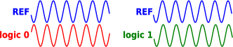
Perhaps the most pressing problem in the progress of electronics and computation is the slowdown of Moore’s law [1, 2]. Among the many design and manufacturing roadblocks, noise and variability are having an ever-greater impact on system performance as transistors are further miniaturized [2]; power consumption has also been a serious concern for many years [3]. While broad directions being explored to address them focus mainly on new devices and new architectures [4, 5, 6], recent research on oscillator-based Boolean computation [7, 8, 9] provides a new perspective: alternative physical representation of logic bits. Instead of using voltage levels, logic values 0 and 1 can be encoded in the relative phase difference of an oscillating signal from a reference signal (Figure 1). Such phase-based encoding features inherently superior noise immunity over level-based encoding; a quick analogy is the use of phase and frequency modulation over amplitude modulation in radio communication for better resistance to noise and interference [10]. This advantage of phase encoding, although having been known in communication for a long time, is yet to be fully exploited in computation.
A key attractiveness of this oscillator-based computation scheme is its generality — almost any nonlinear self-sustaining oscillator can be used as a logic latch. Such an oscillator can be from any physical domain, including electrical (e.g., using CMOS), biological (neurons, intracellular oscillators), nanotechnological (Spin Torque Nano-Oscillators, MEMS resonators), optical (lasers), etc.; there is great potential for high-speed and low-power operation [7, 8]. This generality comes from a mechanism known as injection locking (IL), which is observed in almost all oscillators. Under IL, an oscillator’s response locks on to an oscillating perturbation in both frequency and phase. When the perturbation oscillates at integer multiples of the oscillator’s natural frequency, the oscillator’s phase can lock to the input with multistable sub-harmonic phase-locked responses. This variant of IL is known as Sub-harmonic Injection Locking (SHIL). The sub-harmonic responses can then be used to encode and store logic bits, making the oscillator behave as a logic latch [7]. For example, a binary latch can be implemented by perturbing an oscillator with a small periodic signal at about twice of its natural frequency. The oscillator will develop one of the two bistable responses with a phase difference of , representing 0 or 1 in phase encoding. Together with phase-based combinational logic gates [7], finite state machines can then be implemented for general-purpose Boolean computation.
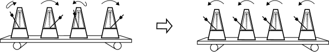
IL is ubiquitous in nature, e.g., the synchronization of fireflies’ patterns, neurons firing in unison, etc.; it is also widely used in engineering. One famous example of IL is the demonstration of metronomes synchronizing their ticks. As illustrated in Figure 2, metronomes placed on a common rolling platform receive small perturbations from their neighbours, and eventually lock to the same frequency with the same phase, despite having slightly different central frequencies and random initial phases.
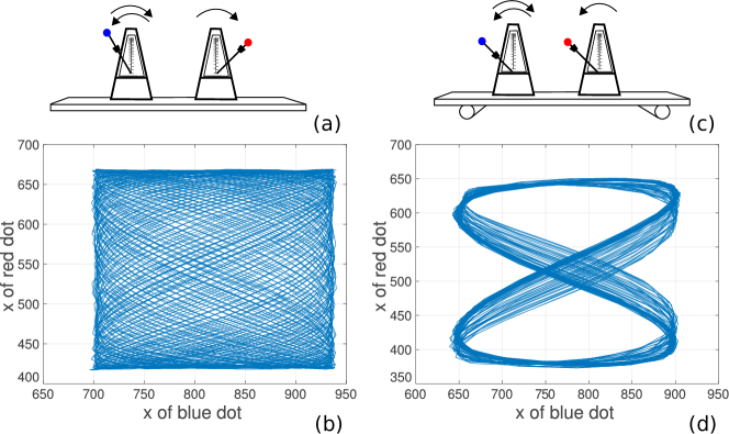
The setup in Figure 2 can also be adapted to demonstrate SHIL [11]. As is shown in Figure 3, on a common platform sit two metronomes — one oscillates at approximately the sub-harmonic of the other. The pendulum tips of the metronomes have colored markers taped to them so that their coordinates can be recorded through processing the video of oscillation. We plot the x coordinates of one metronome’s tip with respect to the other in Figure 3; the resulting curves are known as the Lissajous curves. When the platform is stationary, the Lissajous curves span the whole space, indicating that their phases drift apart; when the platform is rolling, providing injection between the two metronomes, through the mechanism of SHIL their swing patterns synchronize.
When SHIL happens, the oscillator with the sub-harmonic response features bistable phase, allowing it to operate as a binary logic latch. This has been demonstrated in CMOS ring oscillators and LC oscillators [7, 12]. Naturally, a demonstration with metronomes is desirable as it proves the generality of the scheme. For this purpose, the results from Figure 3 are not enough, as logic encoding based on phase requires a reference, e.g., another metronome tuned to approximately 1Hz. However, simply putting another 1Hz metronome on the same platform does not work, as the two 1Hz metronomes will synchronize their phases — the bistability induced by SHIL from the 2Hz oscillator is not strong enough to sustain a phase difference between them for encoding the other logic value. To make the two 1Hz metronomes reliably store a phase-based logic bit, one has to be creative; the conventional setup for metronome experiments has to be changed. In Sec. II, we explore a new experimental setup, where the two 1Hz metronomes swing in directions perpendicular to each other, in order to avoid injection locking between them. Results from this setup are also analyzed in Sec. II, proving that it operates reliably as a binary logic latch that can store a phase-based bit.
All that the experimental setup requires are normal mechanical metronomes111The metronomes used are Wittner Taktell Super-Mini Metronome. and some common household items such as tapes, a foam board and several ping-pong balls; a cell phone is used for video recording and processing the video requires minimal coding experience. The demonstration is both interesting and easily reproducible. As such, it has the potential to reach a broad audience and have a wide impact.
It is worth mentioning that phase-based logic storage has been demonstrated in mechanical systems before. A nanomechanical beam driven by AC power can develop sub-harmonic parametric oscillation with a bistable phase [13, 14]. It has been considered as a first step towards nanomechanical computer [14] using a parametric-oscillator-based (“Parametron”-based) scheme [15, 16, 17, 18]. In comparison, the scheme we have discussed in this paper has several advantages in the potential of miniaturization and system-level routing [7] thanks to the use of DC-powered self-sustaining oscillators. To our knowledge, our work with the metronomes is the first to demonstrate bit storage in the mechanical domain within this oscillator-based computation paradigm.
Another similar work demonstrating phase-based logic bit storage is done recently using chemical reactions [19]. It uses Belousov–Zhabotinsky reaction, which is a self-sustaining chemical oscillator that creates periodically changing color. In the experiments, three Belousov–Zhabotinsky droplets are coupled together. They change color in a merry-go-round fashion; the two stable rotational modes (clockwise and anticlockwise) represent logic value 0 and 1. The demonstration creates the first “one-bit chemical memory unit” or the “chit” [19]. It is worth noting that storing information in clockwise and anticlockwise rotations is a special case of phase-based encoding. In fact, in our experimental setup, when the two 1Hz metronomes oscillate with the two stable phase differences 0 and , the platform they sit on slightly rotates clockwise and anticlockwise respectively. So our demonstration creates a similar one-bit mechanical memory unit with self-sustaining oscillators, the first of its kind.
II Experimental Setup and Results
As discussed in Sec. I, two metronomes tuned to approximately the same frequency (1Hz) are needed to represent a phase-based logic bit. We also need another metronome tuned to about twice of their frequency (2Hz) to provide them with a common injection. Under SHIL, the two 1Hz metronomes will each develop a bistable phase; their phase difference can then be used to store a logic bit.
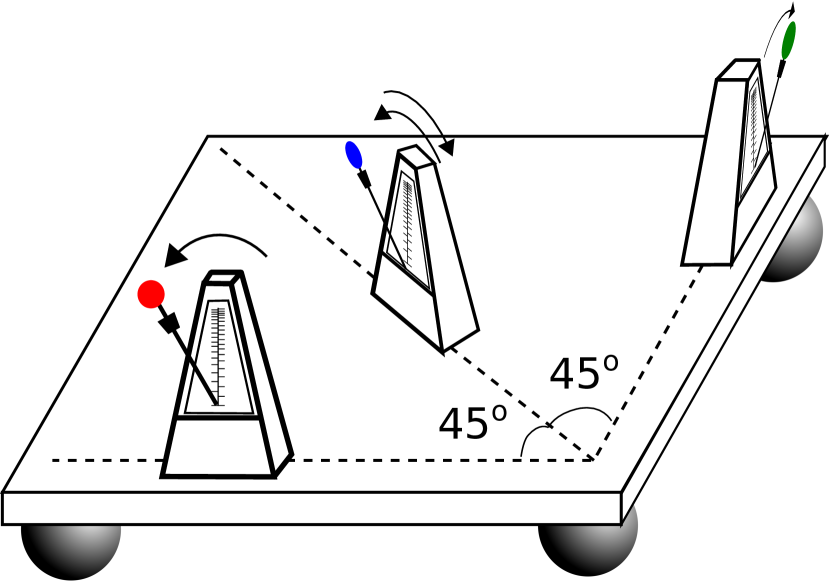
However, we need to make the 2Hz metronome injection lock the two 1Hz ones “independently”, i.e., the two 1Hz ones should not injection lock each other. Towards this end, we design a metronome placement scheme different from the conventional one in Figure 2. The two 1Hz metronomes are placed with a angle, such that the directions in which they swing are perpendicular. To truly decouple them, the platform now needs to be able to roll freely in the horizontal plane. So instead of using cylinders as in Figure 2, we use balls to support the platform on the table. The third metronome, which is tuned to 2Hz, is then placed in between the two 1Hz ones, with a angle from both of them. In this way, its swing injection locks them simultaneously. The setup is illustrated in Figure 4.
There are many everyday objects that can be used as the platform and balls in Figure 4. In practice, we would like to minimize the total mass of the setup in order to maximize the injection between metronomes. Therefore, we use a small foam board instead of wooden ones, and four ping-pong balls instead of marbles. Such details can make a difference in the reliability of the setup and the reproducibility of the results.
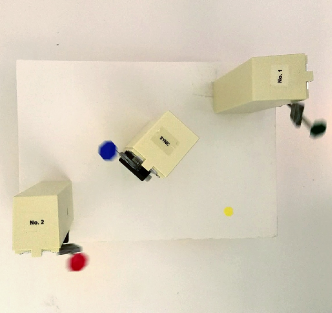
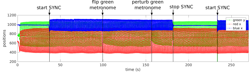
As shown in the photo of the actual setup in Figure 5, the two 1Hz metronomes are taped with red and green markers, the 2Hz one is taped with a blue marker. We start the two 1Hz metronomes first and confirm that their ticking are not synchronized due to frequency detuning. Then we start the 2Hz one. Through the mechanism of SHIL, the two 1Hz metronomes are both frequency locked to the 2Hz one, and they develop a stable phase difference, which stores one logic value. We can manually stop one of the 1Hz metronomes for half a cycle then let it resume its oscillation. After the two 1Hz metronomes are synchronized by the 2Hz one again, their stable phase difference is changed from before by , representing the other binary logic value. We record the whole process using a cell phone with a 60Hz frame rate. The video is imported frame by frame into MATLAB. Then a simple algorithm is used to extract the locations of markers in each frame. Figure 6 shows the oscillation of the coordinates of the markers through the whole experiment of about 270 seconds.
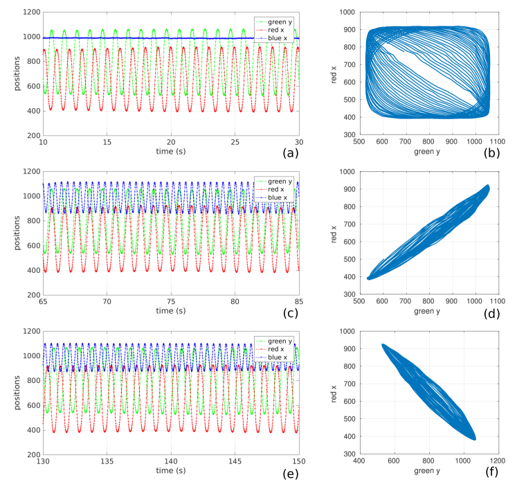
In Figure 7, we show some excerpts from Figure 6. The first excerpt in Figure 7 (a) shows the oscillation of the two 1Hz metronomes from 10s to 30s, during which time the 2Hz one has not been started. Careful observation indicates that the green and red waveforms are not synchronized — the red peak is aligned with the green valley at the beginning of the time slot but has apparently become misaligned towards the end. The corresponding Lissajous curves more clearly show that the phase difference drifts with time. In comparison, the second excerpt (Figure 7 (c)) is taken between time 65s and 85s, when SHIL is present. We observe that the green and red peaks are well aligned, as can be confirmed by the corresponding Lissajous curves in Figure 7 (d). Similarly, after the green metronome’s phase is flipped, from time 130s to 150s, the red peaks are aligned with the green valleys (Figure 7 (e)). This other stable phase difference represents the other phase-encoded logic value. In these two stable states, the corresponding Lissajous curves in Figure 7 (d) and (f) both form a line, but the two lines are perpendicular to each other.
To explore the stability of the stored bit, we perturb the green metronome at about 155s in the experiment, as is shown in Figure 6. Unlike bit flipping, we touch the metronome to slightly delay its oscillation. As a result, the two 1Hz metronomes do not settle to the new phase difference; their previous stable phase difference is restored within ten cycles. This further validates that the setup is a bistable system storing a phase-encoded bit.
III Summary
This paper explores the generality of the key mechanism of oscillator-based Boolean computation by demonstrating bit storage in mechanical metronomes. Through a creative setup, two sub-harmonically injection-locked metronomes have been shown to develop a bistable phase difference of either 0 or , achieving a phase-encoded one-bit mechanical memory. As injection locking is a ubiquitous phenomenon in all types of oscillators, this demonstration has the potential of inspiring more implementations of phase-encoded logic latches using oscillator technologies from various physical domains.
References
- [1] G. E. Moore et al. Cramming More Components onto Integrated Circuits, 1965.
- [2] L. Wilson. International Technology Roadmap for Semiconductors (ITRS). 2013.
- [3] H. Esmaeilzadeh, E. Blem, R. St. Amant, K. Sankaralingam, and D. Burger. Dark Silicon and the End of Multicore Scaling. SIGARCH Comput. Archit. News, 39(3):365–376, June 2011.
- [4] D. Hisamoto, W. C. Lee, J. Kedzierski, H. Takeuchi, K. Asano, C. Kuo, E. Anderson, T.-J. King, J. Bokor, and C. Hu. FinFET—a Self-aligned Double-gate MOSFET Scalable to 20 nm. IEEE Transactions on Electron Devices, 47(12):2320–2325, 2000.
- [5] M. M. Shulaker, G. Hills, N. Patil, H. Wei, H. Chen, H.-S. P. Wong, and S. Mitra. Carbon nanotube computer. Nature, 501(7468):526–530, 2013.
- [6] B. Behin-Aein, D. Datta, S. Salahuddin, and S. Datta. Proposal for an all-spin logic device with built-in memory. Nature nanotechnology, 5(4):266–270, 2010.
- [7] T. Wang and J. Roychowdhury. PHLOGON: PHase-based LOGic using Oscillatory Nanosystems. In Proc. UCNC, LNCS sublibrary: Theoretical computer science and general issues. Springer, July 2014. DOI link.
- [8] J. Roychowdhury. Boolean Computation Using Self-Sustaining Nonlinear Oscillators. Proceedings of the IEEE, 103(11):1958–1969, Nov 2015. DOI link.
- [9] T. Wang and J. Roychowdhury. Oscillator-based Ising Machine. arXiv preprint arXiv:1709.08102, 2017.
- [10] T. S. Rappaport and others. Wireless Communications: Principles and Practice, volume 2. Prentice Hall PTR New Jersey, 1996.
- [11] T. Wang. Sub-harmonic Injection Locking in Metronomes. arXiv preprint arXiv:1709.03886, 2017.
- [12] T. Wang and J. Roychowdhury. Design Tools for Oscillator-based Computing Systems. In Proc. IEEE DAC, pages 188:1–188:6, 2015. DOI link.
- [13] I. Mahboob and H. Yamaguchi. Bit storage and bit flip operations in an electromechanical oscillator. Nature nanotechnology, 3(5):275–279, 2008.
- [14] M. Freeman and W. Hiebert. NEMS: Taking another swing at computing. Nature nanotechnology, 3(5):251–252, 2008.
- [15] J. von Neumann. Non-linear capacitance or inductance switching, amplifying and memory devices. 1954.
- [16] R. L. Wigington. A New Concept in Computing. Proceedings of the Institute of Radio Engineers, 47:516–523, April 1959. DOI link.
- [17] Eiichi Goto. New Parametron circuit element using nonlinear reactance. KDD Kenyku Shiryo, October 1954.
- [18] G. M. K. Eiichi. Resonator circuits. http://www.google.com/patents/US2948818, August 9 1960. US Patent 2,948,818.
- [19] K. Gizynski and J. Gorecki. Chemical memory with states coded in light controlled oscillations of interacting Belousov–Zhabotinsky droplets. Physical Chemistry Chemical Physics, 19(9):6519–6531, 2017.