Negative index and mode coupling in all-dielectric metamaterials at terahertz frequencies
Abstract
We report on the role of the coupling of the modes of Mie resonances in all-dielectric metamaterials to ensure negative effective index at terahertz frequencies. We study this role according to the lattice period and according to the frequency overlapping of the modes of resonance. We show that negative effective refractive index requires sufficiently strong mode coupling and that for even more strong mode coupling, the first two modes of Mie resonances are degenerated; the effective refractive index is then undeterminded. We also show that adjusting the mode coupling leads to near-zero effective index, or even null effective index. Further, we compare the mode coupling effect with hybridization in metamaterials.
1 Introduction
All-dielectric metamaterials (ADM) are the promising “inflection” of metamaterials to go beyond their limits. ADMs are an alternative to metallic metamaterials. The advantages of ADMs come from their low losses and their simple geometry: they do not suffer from ohmic losses and thus benefit from low energy dissipation. From the microwave, their quality factor is greater than that of metallic metamaterials [1] and it is consequently at terahertz and optical frequencies. ADMs are partly inspired by the work of Richtmyer who developed the theory of dielectric resonators, which is based on the fact that “the dielectric has the effect of causing the electromagnetic field […] to be confined to the cylinder itself and the immediately surrounding region of space.” [2]. Taking the matter further, O’Brien and Pendry opened the way for ADMs by considering the periodic lattice of high permittivity resonators (HPR), thus evidencing artificial magnetism in the microwave [3]. ADMs rely on the first two modes of Mie resonances of HPR. The first mode results in resonant effective permeability which can have negative values, while the second one results in resonant effective permittivity which can also have negative values. When the two are simultaneously negative, the ADM is called “double negative” (DNG) and its effective refractive index is then negative [4, 5, 6, 7, 8, 9]. The unit cell of ADM thus comprises two subwavelength building blocks of simple geometry [10, 11]. By analogy with chemical molecules, the unit cell is generally called meta-dimer [12], and the two building blocks are called meta-atoms. As the two are different, the unit cell is a hetero-dimer.
The large applications of ADMs (for a review, see ref. [13]) include perfect reflectors [14], perfect absorbers [15, 16], zero-index metamaterials [17], optical magnetic mirror [18], Fano resonances [19, 20]. ADMs have been demonstrated from microwave to optical domain. Artificial magnetism [21, 1, 22, 23] and negative effective refractive index[24, 25] have been, theoretically and experimentally, evidenced in GHz range. Even though artificial magnetism provided by ADMs has been experimentally demonstrated in the THz range [26] and in the infrared range [27, 28, 29, 30], DNG refractive index has not been yet demonstrated, which impede ADMs to be the equivalent of their metallic counterpart. Besides, terahertz (THz) radiation is widely defined as electromagnetic radiation in the frequency range 0.3-3 THz. Since it permits to obtain physical data which are not accessible using X-ray or infrared radiation, it finds many applications in imaging, security, quality inspection, chemical sensing, astronomy, etc. On their part, metamaterials have evolved towards the implementation of photonic components [31]. HPRs are well suited for metamaterials applications in the low THz frequency range [32].
In the following, we report on the mode coupling effect which plays a dominant role in the electromagnetic properties of metamaterials [33, 34, 35, 36], notably, in the achievement of negative effective index. Magnetic and electric mode coupling effects in ADMs have been separately studied from each other in the microwave by Zhang et al [34]. Herein, we report on the magneto-electric mode coupling effects going up the terahertz domain, and we show that negative effective refractive index requires sufficiently strong mode coupling [37]. We also show that adjusting the mode coupling allows to attain near-zero values of the refractive index, or even null effective index. Moreover, we highlight that the strongest values of the mode coupling lead to frequency mode degeneracy, for which the refractive index is undetermined.
2 Simulations
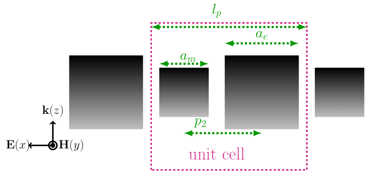
We considered a 2D ADM whose unit cell consists of two distinct building blocks, a magnetic block and an electric one, the former resonating in the first mode of Mie resonances and the latter resonating in the second mode [1, 11, 25, 38]. The first mode is thus referred to as the magnetic mode and the second one to as the electric mode. The ADM consists of one infinite layer made up of two sets of high permittivity square cross-section dielectric cylinders which are perpendicular to the incident wave vector (Fig. 1). The two sets of HPRs are actually interleaved. The incident polarization is Transverse Electric (TE), i.e., the electric field is perpendicular to the axis of the cylinders. We studied both spatial mode coupling and frequency mode coupling. The ADM has been numerically simulated by the means of the finite elements method software HFSS™ which yields the -parameters. The side lengths of the resonators are initially for the magnetic mode and for the electric one, the lattice period being . The HPRs are equidistant and therefore, the distance between two of them is half the lattice period . The relative permittivity of the dielectric is (Titanium dioxyde - ) and the loss tangent increases between = 0.009 and 0.015 in the considered frequency range [39, 40]. Thus, we are dealing with a high refractive index bulk material ( 10)
3 Results and discussion
3.1 Negative index and mode coupling
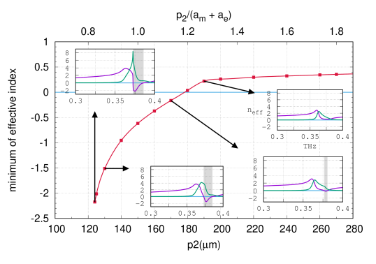
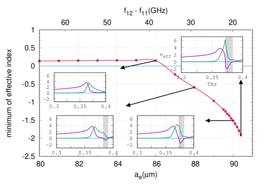
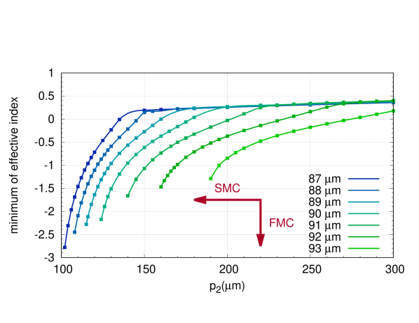
We studied the mode coupling between the first two modes of Mie resonances depending on the lattice period (spatial mode coupling), and then depending on the frequency overlapping of the two modes (frequency mode coupling). The results of the simulation, namely the minimum of the effective index in function the lattice period and in function of the frequency spacing between the two modes, are reported in Fig. 2 and 3, respectively. They show that the mode coupling should be strong enough to ensure negative effective index. The minima of the effective index are = -2.2 and -1.9, respectively. In the one hand, increasing the mode coupling is obtained by decreasing the lattice period . On the other hand, it is obtained by decreasing the frequency of the second mode of Mie resonances, which derives from the increasing of the side length of the electric resonator. When the mode coupling is sufficient, the bandwidth of the negative effective index increases with it (see insets in Fig. 2 & 3). The frequency range of negative effective index is given by the relation [41]
| (1) |
where ′ and ′′ respectively denote the real and imaginary parts of the permeability and the permittivity .
3.2 Monomode coupling
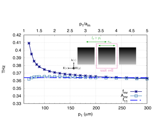
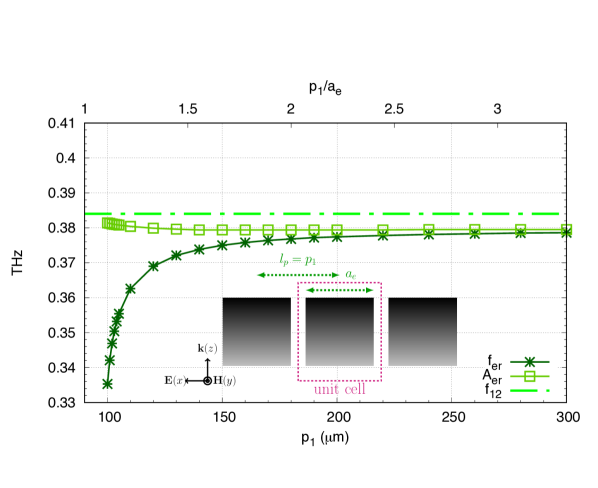
To carry out our study, we firstly studied monomode coupling, that is, the mode coupling due to only one mode, which arises inside a layer whose unit cell only consists of one building block, the magnetic one or the electric one. We studied both cases. Consequently, we had to only consider the spatial mode coupling and we only varied the lattice period which is equal to the distance between two resonators, . Operating in the same frequency range, the side length of the magnetic resonator is , while that of the electric resonator is . The results of the simulation are reported in Fig. 4 and 5, for both cases, and they show that the two modes differently behave. Their respective frequencies (, ) are given by the minima of the parameter [34]. The frequency of the magnetic mode increases with the lattice period , whereas the frequency of the electric one decreases. These results are consistent with that of reference [34]. Both maxima of the absorption and () and the frequency of the resonance modes of the individual resonator are also reported. This latter provides a series of resonances whose frequency is determined by Cohn’s model [42, 43, 44]
| (2) |
where is the relative permittivity of the resonator, and are integers, and are the side lengths of the resonator and is the velocity of light and its accuracy is about 5%. Equation 2 was used to design all the reported structures. For square cross section cylinder, , and the frequencies of the first two modes of the individual resonator respectively correspond to and and . To exhibit negative refractive index, the involved resonance modes are the first mode of the magnetic resonator and the second mode of the electric resonator. Their frequencies are respectively THz () and THz () [25]. These are obviously constant, while the maxima of the absorption are practically constant. It can be noticed that, as the mode coupling increases, the distance between the resonance frequencies (, ) of the resonator inside the layer and that (, ) of the individual resonator respectively increases (cf. Fig. 4 and 5, respectively), thus evidencing the mode coupling.
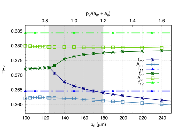
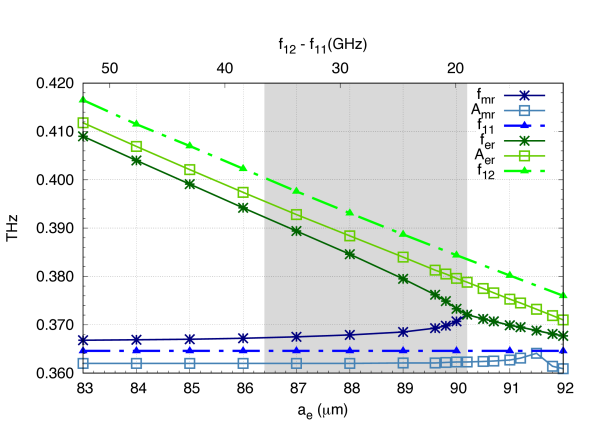
3.3 Bimode coupling
Then, we studied the mode coupling inside the ADM, namely, the unit cell now consists of the two building blocks. The variation of the resonance frequencies (, ) of both modes is reported in Fig. 6 and 7 corresponding to the spatial mode coupling and the frequency mode coupling, respectively. These frequencies are still given by the minima of the parameter [34]. Decreasing the lattice period , i.e., the distance between the resonators, increases the mode coupling. Varying the overlapping of the two modes stems from the decreasing of the frequency of the electric mode, which also increases the mode coupling [33]. The curves are shaped as “tuning forks” and show that the frequencies (, ) of the two modes of resonance are moving closer as the mode coupling increases. To highlight this effect, the frequencies (, ) of the resonance modes of the individual resonator are again shown in these figures. For both the magnetic mode and the electric one, the distance between the frequency (, ) of the resonator inside the ADM and the frequency (, ) of the individual one respectively increases as the mode coupling increases. This anew evidences the mode coupling inside the ADM. Theses curves also evidence that further increasing the mode coupling gives rise to a frequency degeneracy in both cases of mode coupling, that is, the two resonance frequencies of the two modes become equal, = .
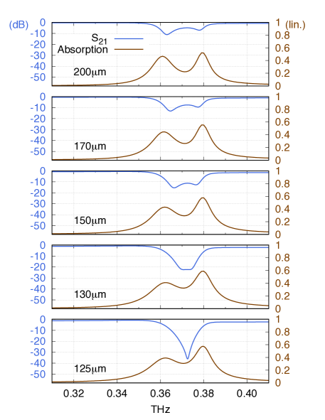
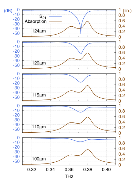
The parameter and the absorption are reported in Fig. 8 in function of the frequency for several values of the lattice period , which is relative to the spatial mode coupling. Two ranges of the lattice period are considered, one is out of the frequency degeneracy regime () and the second one in the frequency degeneracy regime (). It can be noticed that the frequency of both maxima of the absorption are practically constant, whereas the frequency of both minima of the parameter are varying according to the lattice period . These latter get closer as the lattice period increases, until to be merged, which corresponds to the frequency degeneracy. The crossing point is reached when the lattice period is equal to . The merged minima of the parameter attain very weak value ( -51dB) for , which corresponds to the minimum of the effective index = -2.2. (See effective index curves inserted in Fig. 2 and Fig. 3 which are continuous, but are on the limit of continuity.) For greater values of the mode coupling, that is, for lattice period smaller than 248, the effective parameters could not be extracted, being not continuous through all frequencies [45]; the effective refractive index is then undetermined. We observed the same frequency degeneracy behavior when studying the frequency mode coupling (results not shown).
The mode coupling effect we report on is different from hybridization [46] which is observed with plasmonic metameterial [12, 47], split-ring resonators metametarials [48], inductor-capacitor resonators [49], cut wires [50], nanowires [51], nano-rings [52], nano-particle dimers [53] or silicon nanoparticles [54]. In the latter cases, the coupling between the two identical meta-atoms which constitute the dimer leads from a trapped mode to the formation of new hybridized modes because it lifts the degeneracy of the mode of the individual meta-atoms. Hybridization may be used to yield negative refractive index[49, 48, 52]. The unit cell is then a homo-dimer and the negative effective index is achieved by playing with the mode coupling so as to overlap two hybridized modes which are of different kind: magnetic or electric. In the case we report on, the mechanism is different since it takes the reverse way, because increasing the mode coupling leads from two separated modes to a trapped one. The unit cell of our ADM is a hetero-dimer because the two meta-atoms are not identical and moreover, each one resonates in a different kind of mode: the magnetic one and the electric one. Hence, increasing the mode coupling leads to the trapped mode putting together the two separated modes. Nevertheless, the mode coupling has to be strong enough to ensure negative effective index, the unit cell being either a homo-dimer or a hetero-dimer.
 |
 |
| (a) | (b) |
3.4 Effective parameters
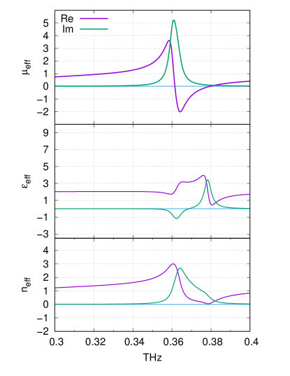
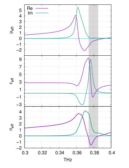
In our ADM, a magnetic moment ensues from the magnetic mode giving rise to resonant effective permeability . Similarly, an electric moment ensues from the electric mode giving rise to resonant effective permittivity . The two of them are perpendicular to each other (see e.g., Fig.1 in reference [38]). The mode coupling arises from the interaction between these electromagnetic moments and it changes with the distance between them. The side lengths of the resonators are afresh and . Both resonances consequently modify the effective refractive index of the ADM. The effective electromagnetic parameters , and are reported in Fig. 9 relative to two values of the lattice period m and m. They are extracted from the -parameters using the common retrieval method described in ref. [55, 56, 57, 58, 59, 60, 45]. The antiresonance behavior of the effective permittivity around the magnetic mode frequency, which is inherent in metamaterials, can be observed [60, 61, 62, 63]. In the former case (low mode coupling), the effective index does not reach negative values, whereas it does in the latter case (strong mode coupling), then satisfying equation 1. The minimum value of the effective index is then . In the former case, the effective index is below unity and close to zero. Its minimal value is , evidencing that adjusting the mode coupling makes ADMs suitable for epsilon-near-zero (ENZ) metamaterials [64, 65] (see also Fig. 2), or even null effective index [17]. It can also be noticed that the mode coupling strongly enhances the amplitude of both resonances, notably the electric one, and that it brings closer the two modes. Besides, as we are dealing with a high refractive index bulk material ( 10), the wavelength inside it is about one-tenth of that in vacuum. Consequently, we calculated the static effective permittivity, i.e., beyond the resonances, from the Maxwell-Garnett model [66]. It is equal to and corresponding to both values of the lattice period m and m, respectively, which is in good agreement with the results of the simulation.
 |
 |
| (a) | (b) |
To engineer the electromagnetic properties of an ADM, one can consequently play with either mode couplings: the spatial mode coupling or the frequency mode coupling. Fig. 10 gather the role of both mode couplings: the stronger the two mode couplings, the more negative the effective index and the larger the bandwidth of negative effective index (cf. Fig. 2 and 3). Combining the two mode couplings, negative effective index as low as is obtained.
3.5 Dielectric function, phonons and strontium titanate ()
Others high permittivity materials, having low losses, can be investigated to study the mode coupling inside ADMs at terahertz frequencies, e.g., [67, 68, 69, 70]. However, the dielectric function of these high permittivity materials is dispersive, because of the lattice vibrations, namely, the optical phonons [71]. Their frequency is in the THz range, and we are concerned by the transverse optical phonon of lowest frequency (TO1). The TO1 phonon frequency of is 2.70 THz[67], while that of is 5.6 THz [67, 71]. The dielectric function is described by the classical oscillator model or the Four-Parameter Semi Quantum (FPSQ) model[67, 71]. Measurements at THz frequency, reported in the literature, are in good agreement with these models for [39, 40] and [70, 72, 69, 73]. The two yield the same dielectric function at the operating frequency. We also simulated a similar ADM but consisting of HPRs made of and found that it exhibits the same mode coupling effect (results not shown herein). The effective index reaches values as low as , meaning that the effect of the mode coupling is stronger when a higher permittivity material is used ( [70] instead of ), because this heightens the resonances.
However, losses (imaginary part of ) resulting from the TO1 phonon greatly increase and therefore limits the operating range at terahertz frequencies. Besides, the real part of the dielectric function falls down at higher frequency [72, 70], which drastically modifies the Mie resonances. The lower permittivity of leads to greater side lengths and of each resonator (see equation 2) and therefore, it facilitates their fabrication. Consequently, is more suitable for ADM applications at THz frequencies.
4 Conclusion
We have studied mode coupling effects in ADMs at terahertz frequencies and we show that the mode coupling has to be sufficiently strong to ensure negative effective index of refraction. Tuning the first two modes of Mie resonances of an ADM by adjusting the mode coupling allows to set the effective index from a near-zero value to a negative value. We studied both spatial mode coupling and frequency mode coupling. Increasing both brings the modes closer until they are merged. Thus, we highlight the frequency degeneracy of the first two resonance modes, namely, the two frequencies are equal, and the effective index is then undetermined. At the crossing point, the effective index reaches its lowest value.
5 Author contributions
É.A. supervised the study, analyzed the results and wrote the paper. S.M. made the simulation and analyzed the results.
References
- [1] Popa B I and Cummer S A 2008 Phys. Rev. Lett. 100(20) 207401 URL http://link.aps.org/doi/10.1103/PhysRevLett.100.207401
- [2] Richtmyer R D 1939 Journal of Applied Physics 10 391–398 URL http://scitation.aip.org/content/aip/journal/jap/10/6/10.1063/1.1707320
- [3] O’Brien S and Pendry J B 2002 Journal of Physics: Condensed Matter 14 4035
- [4] Pendry J B and Smith D R 2004 Physics Today 57 37–43
- [5] Padilla W J, Basov D N and Smith D R 2006 Materials Today 9 28 – 35 ISSN 1369-7021 URL http://www.sciencedirect.com/science/article/pii/S1369702106715735
- [6] Smith D R, Padilla W J, Vier D C, Nemat-Nasser S C and Schultz S 2000 Phys. Rev. Lett. 84(18) 4184–4187 URL http://link.aps.org/doi/10.1103/PhysRevLett.84.4184
- [7] Ziolkowski R W 2003 IEEE Transactions on Antennas and Propagation 51 1516–1529 ISSN 0018-926X
- [8] Engheta N and Ziolkowski R W 2005 IEEE Transactions on Microwave Theory and Techniques 53 1535–1556 ISSN 0018-9480
- [9] Liu R, Degiron A, Mock J J and Smith D R 2007 Applied Physics Letters 90 263504 URL http://scitation.aip.org/content/aip/journal/apl/90/26/10.1063/1.2752120
- [10] Ahmadi A and Mosallaei H 2008 Phys. Rev. B 77(4) 045104 URL http://link.aps.org/doi/10.1103/PhysRevB.77.045104
- [11] Zhao Q, Zhou J, Zhang F and Lippens D 2009 Materials Today 12 60 – 69 ISSN 1369-7021 URL http://www.sciencedirect.com/science/article/pii/S1369702109703189
- [12] Liu N, Liu H, Zhu S and Giessen H 2009 Nature Photonics 3 157–162
- [13] Jahani S and Jacob Z 2016 Nat Nano 11 23–36 URL http://dx.doi.org/10.1038/nnano.2015.304
- [14] Moitra P, Slovick B A, li W, Kravchencko I I, Briggs D P, Krishnamurthy S and Valentine J 2015 ACS Photonics 2 692–698 URL http://dx.doi.org/10.1021/acsphotonics.5b00148
- [15] Liu X, Zhao Q, Lan C and Zhou J 2013 Applied Physics Letters 103 031910
- [16] Liu X, Bi K, Li B, Zhao Q and Zhou J 2016 Opt. Express 24 20454–20460 URL http://www.opticsexpress.org/abstract.cfm?URI=oe-24-18-20454
- [17] Moitra P, Yang Y, Anderson Z, Kravchenko I I, Briggs D P and Valentine J 2013 Nat Photon 7 791–795
- [18] Liu S, Sinclair M B, Mahony T S, Jun Y C, Campione S, Ginn J, Bender D A, Wendt J R, Ihlefeld J F, Clem P G, Wright J B and Brener I 2014 Optica 1 250–256 URL http://www.osapublishing.org/optica/abstract.cfm?URI=optica-1-4-250
- [19] Luk’yanchuk B, Zheludev N I, Maier S A, Halas N J, Nordlander P, Giessen H and Chong C T 2010 Nat Mater 9 707–715
- [20] Lepetit T, Akmansoy E, Ganne J P and Lourtioz J M 2010 Phys. Rev. B 82(19) 195307 URL http://link.aps.org/doi/10.1103/PhysRevB.82.195307
- [21] Zhao Q, Kang L, Du B, Zhao H, Xie Q, Huang X, Li B, Zhou J and Li L 2008 Phys. Rev. Lett. 101(2) 027402 URL http://link.aps.org/doi/10.1103/PhysRevLett.101.027402
- [22] Lepetit T, Akmansoy E, Pate M and Ganne J P 2008 Electronics Letters 44 1119–1120 ISSN 0013-5194
- [23] Vendik I, Odit M and Kozlov D 2009 Metamaterials 3 140 – 147
- [24] Kim J and Gopinath A 2007 Phys. Rev. B 76(11) 115126 URL http://link.aps.org/doi/10.1103/PhysRevB.76.115126
- [25] Lepetit T, Akmansoy É and Ganne J P 2009 Applied Physics Letters 95 121101 URL http://scitation.aip.org/content/aip/journal/apl/95/12/10.1063/1.3232222
- [26] Nemec H, Kuzel P, Kadlec F, Kadlec C, Yahiaoui R and Mounaix P 2009 Physical Review B (Condensed Matter and Materials Physics) 79 241108
- [27] Wheeler M S, Aitchison J S, Chen J I L, Ozin G A and Mojahedi M 2009 Phys. Rev. B 79 073103
- [28] Ginn J C, Brener I, Peters D W, Wendt J R, Stevens J O, Hines P F, Basilio L I, Warne L K, Ihlefeld J F, Clem P G and Sinclair M B 2012 Phys. Rev. Lett. 108(9) 097402 URL http://link.aps.org/doi/10.1103/PhysRevLett.108.097402
- [29] Schuller J A, Zia R, Taubner T and Brongersma M L 2007 Phys. Rev. Lett. 99(10) 107401 URL http://link.aps.org/doi/10.1103/PhysRevLett.99.107401
- [30] Shi L, Tuzer T U, Fenollosa R and Meseguer F 2012 Advanced Materials 24 5934–5938 ISSN 1521-4095 URL http://dx.doi.org/10.1002/adma.201201987
- [31] Zheludev N I and Kivshar Y S 2012 Nat Mater 11 917–924
- [32] Gaufillet F, Marcellin S and Akmansoy E 2017 IEEE Journal of Selected Topics in Quantum Electronics 23 1–5 ISSN 1077-260X
- [33] Liu N and Giessen H 2010 Angewandte Chemie International Edition 49 9838–9852 ISSN 1521-3773 URL http://dx.doi.org/10.1002/anie.200906211
- [34] Zhang F, Kang L, Zhao Q, Zhou J and Lippens D 2012 New Journal of Physics 14 033031 URL http://stacks.iop.org/1367-2630/14/i=3/a=033031
- [35] Zhang F, Sadaune V, Kang L, Zhao Q, Zhou J and Lippens D 2012 Progress In Electromagnetics Research-Pier 132 587–601
- [36] Lannebère S, Campione S, Aradian A, Albani M and Capolino F 2014 J. Opt. Soc. Am. B 31 1078–1086 URL http://josab.osa.org/abstract.cfm?URI=josab-31-5-1078
- [37] Marcellin S and Akmansoy E 2015 Negative index and mode coupling in all-dielectric metamaterials at terahertz frequencies 2015 9th International Congress on Advanced Electromagnetic Materials in Microwaves and Optics (METAMATERIALS) pp 4–6
- [38] Lepetit T, Akmansoy E and Ganne J P 2011 Journal of Applied Physics 109 023115
- [39] Matsumoto N, Hosokura T, Kageyama K, Takagi H, Sakabe Y and Hangyo M 2008 Japanese Journal of Applied Physics 47 7725 URL http://stacks.iop.org/1347-4065/47/i=9S/a=7725
- [40] Berdel K, Rivas J, Bolivar P, de Maagt P and Kurz H 2005 IEEE Transactions On Microwave Theory And Techniques 53 1266–1271
- [41] Depine R A and Lakhtakia A 2004 Microw. Opt. Techn. Lett. 41 315–316
- [42] Cohn S B 1968 IEEE Transactions on Microwave Theory and Techniques 16 218–227 ISSN 0018-9480
- [43] Kajfez D and Guillon P 1986 Dielectric resonators (Artech house)
- [44] Sethares J and Naumann S 1966 IEEE Transactions On Microwave Theory And Techniques MT14 2–& ISSN 0018-9480
- [45] Chen X, Grzegorczyk T M, Wu B I, Pacheco J and Kong J A 2004 Phys. Rev. E 70(1) 016608 URL http://link.aps.org/doi/10.1103/PhysRevE.70.016608
- [46] Prodan E, Radloff C, Halas N J and Nordlander P 2003 Science 302 419–422 ISSN 0036-8075 (Preprint http://science.sciencemag.org/content/302/5644/419.full.pdf) URL http://science.sciencemag.org/content/302/5644/419
- [47] Guo H, Liu N, Fu L, Meyrath T P, Zentgraf T, Schweizer H and Giessen H 2007 Opt. Express 15 12095–12101 URL http://www.opticsexpress.org/abstract.cfm?URI=oe-15-19-12095
- [48] Abdeddaim R, Ourir A and de Rosny J 2011 Phys. Rev. B 83(3) 033101 URL http://link.aps.org/doi/10.1103/PhysRevB.83.033101
- [49] Shen N H, Zhang L, Koschny T, Dastmalchi B, Kafesaki M and Soukoulis C M 2012 Applied Physics Letters 101 URL http://scitation.aip.org/content/aip/journal/apl/101/8/10.1063/1.4748361
- [50] Liu N, Guo H, Fu L, Kaiser S, Schweizer H and Giessen H 2007 Advanced Materials 19 3628–3632 ISSN 1521-4095 URL http://dx.doi.org/10.1002/adma.200700123
- [51] Christ A, Martin O J F, Ekinci Y, Gippius N A and Tikhodeev S G 2008 Nano Letters 8 2171–2175 pMID: 18578551 URL http://dx.doi.org/10.1021/nl0805559
- [52] Kanté B, Park Y S, O’Brien K, Shuldman D, Lanzillotti-Kimura N D, Jing Wong Z, Yin X and Zhang X 2012 Nat Commun 3 1180
- [53] Nordlander P, Oubre C, Prodan E, Li K and Stockman M I 2004 Nano Letters 4 899–903
- [54] van de Groep J, Coenen T, Mann S A and Polman A 2016 Optica 3 93–99 URL http://www.osapublishing.org/optica/abstract.cfm?URI=optica-3-1-93
- [55] Nicolson A M and Ross G F 1970 IEEE Trans. Instrum. Meas. 19 377–382
- [56] Weir W 1974 Proc. IEEE 62 33–36
- [57] Szabo Z, Park G H, Hedge R and Li E P 2010 IEEE Transactions on Microwave Theory and Techniques 58 2646–2653 ISSN 0018-9480
- [58] Varadan V and Ro R 2007 Microwave Theory and Techniques, IEEE Transactions on 55 2224–2230 ISSN 0018-9480
- [59] Smith D R, Schultz S, Markoš P and Soukoulis C M 2002 Phys. Rev. B 65(19) 195104 URL http://link.aps.org/doi/10.1103/PhysRevB.65.195104
- [60] Koschny T, Markoš P, Smith D R and Soukoulis C M 2003 Phys. Rev. E 68(6) 065602 URL http://link.aps.org/doi/10.1103/PhysRevE.68.065602
- [61] Smith D R, Vier D C, Koschny T and Soukoulis C M 2005 Phys. Rev. E 71(3) 036617 URL http://link.aps.org/doi/10.1103/PhysRevE.71.036617
- [62] Alù A 2011 Phys. Rev. B 83(8) 081102 URL http://link.aps.org/doi/10.1103/PhysRevB.83.081102
- [63] Simovski C R 2011 Journal of Optics 13 013001 URL http://stacks.iop.org/2040-8986/13/i=1/a=013001
- [64] Ziolkowski R W 2004 Phys. Rev. E 70(4) 046608 URL http://link.aps.org/doi/10.1103/PhysRevE.70.046608
- [65] Alù A, Silveirinha M G, Salandrino A and Engheta N 2007 Phys. Rev. B 75(15) 155410 URL http://link.aps.org/doi/10.1103/PhysRevB.75.155410
- [66] Sihvola A 2005 Progress In Electromagnetics Research-Pier 51 65–82 ISSN 1559-8985
- [67] Spitzer W G, Miller R C, Kleinman D A and Howarth L E 1962 Phys. Rev. 126(5) 1710–1721 URL http://link.aps.org/doi/10.1103/PhysRev.126.1710
- [68] Barker A S 1966 Phys. Rev. 145(2) 391–399 URL http://link.aps.org/doi/10.1103/PhysRev.145.391
- [69] Han J, Wan F, Zhu Z and Zhang W 2007 Applied Physics Letters 90 –
- [70] Matsumoto N, Fujii T, Kageyama K, Takagi H, Nagashima T and Hangyo M 2009 Japanese Journal of Applied Physics 48 09KC11 URL http://stacks.iop.org/1347-4065/48/i=9S1/a=09KC11
- [71] Gervais F m c and Piriou B 1974 Phys. Rev. B 10(4) 1642–1654 URL http://link.aps.org/doi/10.1103/PhysRevB.10.1642
- [72] Tsurumi T, Li J, Hoshina T, Kakemoto H, Nakada M and Akedo J 2007 Applied Physics Letters 91 182905 URL http://scitation.aip.org/content/aip/journal/apl/91/18/10.1063/1.2804570
- [73] Petzelt J, Ostapchuk T, Gregora I, Rychetský I, Hoffmann-Eifert S, Pronin A V, Yuzyuk Y, Gorshunov B P, Kamba S, Bovtun V, Pokorný J, Savinov M, Porokhonskyy V, Rafaja D, Vaněk P, Almeida A, Chaves M R, Volkov A A, Dressel M and Waser R 2001 Phys. Rev. B 64(18) 184111 URL http://link.aps.org/doi/10.1103/PhysRevB.64.184111