Nonlinear absorption in dielectric metamaterials
Abstract
We solve the nonlinear Maxwell equations in an InP-based dielectric metamaterial, considering both two-photon absorption and photo-induced free-carrier absorption. We obtain the intensity-dependent reflection, absorption, and effective permittivity and permeability of the metamaterial. Our results show that nonlinear absorption dampens both the electric and magnetic Mie resonance, although the magnetic resonance is more affected because it occurs at longer wavelengths where the free-carrier absorption cross section is larger. Owing to field concentration in the metamaterial at resonance, the threshold intensity for nonlinear absorption is smaller by a factor of about 30 compared to a homogeneous layer of the same thickness. Our results have implications on the use of dielectric metamaterials for nonlinear applications such as frequency conversion and optical limiting.
Materials with strong nonlinear response are desired for applications involving optical limiting Stryland et al. (1985); Boggess et al. (1985); Stryland et al. (1988), ultrafast modulation Scalora et al. (1994); Tran (1997); Hache and Bourgeois (2000), frequency conversion Rashkeev and Lambrecht (2001); Lekse et al. (2009), and optical isolation Gallo and Assanto (1999); Yu and Fan (2009). Traditional bulk materials have a weak interaction between electrons and sub-bandgap photons, as measured by nonlinear absorption coefficients Chang et al. (2014); Bechtel and Smith (1976); Boggess et al. (1986); Krishnamurthy et al. (2011), and thus require high intensities or long interaction lengths to achieve an efficient nonlinear response.
One way to enhance the nonlinear response is to incorporate metamaterial elements or plasmonic structures to concentrate the electric fields within a nonlinear material Kauranen and Zayats (2012); Schuller et al. (2010). Metamaterials containing plasmonic nanostructures have been integrated with nonlinear materials to enhance second-harmonic generation Czaplicki et al. (2013); Aouani et al. (2012); Thyagarajan et al. (2012, 2013); Zhang et al. (2011); Harutyunyan et al. (2012); Navarro-Cia and Maier (2012) and achieve analog electromagnetically induced transparency Gu et al. (2012); Kurter et al. (2011). The drawback of plasmonic approaches is that the fields are highly localized at the metal dielectric interface, leading to small interaction volumes Shcherbakov et al. (2014); Yang et al. (2015). Also, the finite conductivity of metals at optical frequencies leads to undesirable losses. An alternative approach is to induce nonlinearity in dielectric metamaterials using Mie resonances Kapitanova et al. (2017). Dielectric nanostructures have been used to enhance third-harmonic generation Shcherbakov et al. (2014); Yang et al. (2015); Shcherbakov et al. (2015a); Smirnova et al. (2016); Grinblat et al. (2016); Shorokhov et al. (2016) and to achieve ultrafast optical modulation Shcherbakov et al. (2015b); Makarov et al. (2015); Baranov et al. (2016).
To date, the research on nonlinear phenomena in dielectric metamaterials has focused primarily on the experimental aspects Shcherbakov et al. (2014); Yang et al. (2015); Shcherbakov et al. (2015a); Smirnova et al. (2016); Grinblat et al. (2016); Shorokhov et al. (2016), with relatively few examples of theoretical studies. A few examples employ the recently-developed linear generalized source method for nonlinear materials Weismann et al. (2015); Weismann and Panoiu (2016); Kruk et al. (2015), which calculates the diffraction of one- and two-dimensional gratings accounting for nonlinear polarization sources. Although these models provide important insights, they do not support three-dimensional structures and do not represent full solutions of the nonlinear Maxwell equations. Also, existing models do not account for the nontrivial frequency dependence of the nonlinear parameters, such as the two photon absorption (TPA) coefficient and the free-carrier absorption (FCA) cross section Krishnamurthy et al. (2011).
In this work, we develop a full-wave model to solve the nonlinear Maxwell equations in a structured, three-dimensional metamaterial accounting for both TPA and photo-induced FCA. The nonlinear absorption coefficients are obtained from full-band structure calculations Krishnamurthy et al. (2011). We apply the model to study the optical properties and effective parameters of a representative indium phosphide (InP)-based dielectric metamaterial operating in the near infrared spectral band. As expected, we find that nonlinear absorption at high intensities leads to dampening of the electric and magnetic Mie resonances. For continuous wave illumination, the onset of nonlinear absorption occurs at intensities of 1 MW/cm2, while the Mie resonances are almost completely diminished for intensities approaching 5 MW/cm2. In addition, we find several unexpected results. First, the nonlinear absorption at the magnetic resonance is larger than at the electric resonance, which is explained by the wavelength-dependent FCA. Second, assuming FCA is independent of wavelength, the absorption at the two resonances is found to be nearly equal, despite the electric field being heavily localized at the electric resonance and more uniformly distributed at the magnetic resonance. Third, owing to the enhancement of the electric field at resonance, we find that the intensity threshold of nonlinear absorption in the metamaterial is nearly 30 times lower compared to a homogeneous material of similar thickness.
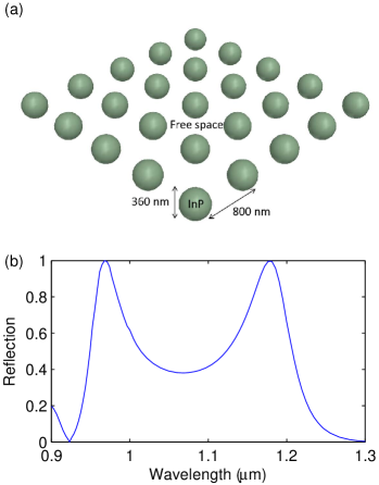
To clearly illustrate the effects of nonlinearity on Mie resonances, we consider a large index-contrast metamaterial consisting of 360 nm InP spheres with large refractive index (3.3 at 1 m) in air medium, arranged in a square lattice with a periodicity of 800 nm, as shown in Fig. 1(a). InP is chosen for its transparency in the near-infrared band of interest (0.9-1.3 m). Note that the conclusions drawn in this article are valid even if the air medium is replaced by a polymer and the metamaterial layer is placed on a low index substrate such as silica. The size and periodicity of the InP spheres are optimized to position the electric and magnetic Mie resonances, identified as narrowband peaks in the reflection spectrum, in the band of interest as shown in Fig. 1(b).
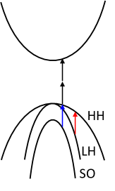
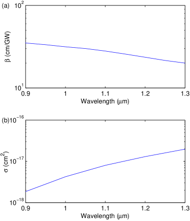
The origin of nonlinear absorption in InP can be understood from the band structure, shown in Fig. 2. The valence bands (VBs) consist of heavy-hole (HH), light-hole (LH), and spin-orbit (SO) bands. The conduction band (CB) is separated from the HH band by the band gap. In the absence of light, states in the VB are filled with electrons and the CB states are empty. Electrons in the VB can absorb photons with energy larger than the band gap and enter the CB. Since the band gap of InP (1.45 eV) is larger than the photon energies in the band of interest (0.95-1.4 eV), at low intensities photons transmit through InP without absorption. However, when the incident intensity is high, the probability for valence electrons to absorb two photons (shown as two stacked vertical arrows) is high, resulting in reduced transmission. In addition, this TPA is followed by FCA in which the holes left behind in the HH band can be filled by one-photon absorption by electrons in the LH and SO bands, shown by the colored arrows in Fig. 2. Because the strength of both TPA and FCA depend on intensity, they are referred to as nonlinear absorption processes. Figure 3 shows the previously calculated values of the TPA coefficient and the FCA cross section for InP Krishnamurthy et al. (2011). The value of is relatively constant with wavelength, which is typical for wide-bandgap materials, while increases by an order of magnitude over the band. The FCA increases with increasing wavelength because the corresponding photon energy decreases, and the energy-momentum conservation condition for FCA (colored lines in Fig. 2) is satisfied only near the center of the Brillouin zone, where a larger number of holes are present.
We will now incorporate these nonlinear coefficients into Maxwell’s equations. The nonlinear Maxwell equation for the electric field is Shen (1984); Stegeman and Stegeman (2012)
| (1) |
where is the refractive index, is the speed of light, and are the free-carrier concentration and absorption cross section, is the free-space permittivity, and is the nonlinear polarization. Taking the Fourier transform of Eq. (1), assuming an time dependence, and using the relation for the third-order nonlinear polarization
| (2) |
where is the nonlinear susceptibility, we obtain
| (3) |
Relating the imaginary part of to the two-photon absorption coefficient as Shen (1984); Stegeman and Stegeman (2012)
and neglecting the real part of , Eq. (3) can be rewritten as
| (4) |
The free carrier concentration is given by the continuity equation for free electrons Shen (1984); Krishnamurthy et al. (2011); Stegeman and Stegeman (2012)
| (5) |
where is the intensity, is the photon energy and is the photo-carrier relaxation time, which we assume is a constant equal to 1 s. The first term in Eq. (5) describes free-carrier generation via TPA, and the second term describes free carrier recombination. For continuous-wave illumination, the free-carrier concentration will reach steady state conditions () and thus
| (6) |
Substituting Eq. (6) into Eq. (4), we obtain the following form of the nonlinear Maxwell equation:
| (7) | |||||
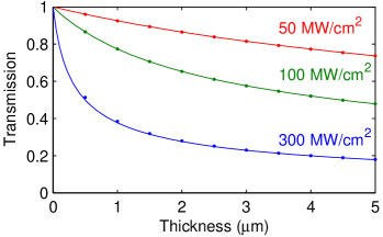
We solve Eq. (7) using the full-wave finite-element frequency domain solver in COMSOL. This was accomplished by assigning the two nonlinear terms in Eq. (7) to the imaginary part of . Before solving Eq. (7) in the metamaterial in Fig. 1, we apply it to a homogeneous nonlinear medium and compare the results with the solution to the well-known rate equation Shen (1984); Stegeman and Stegeman (2012)
| (8) |
The transmitted intensity, as a function of thickness for InP at a wavelength of 1 m for various intensities, calculated by solving Eq. (7) and (8), respectively, are shown by dots and solid lines in Fig. 4. The two calculations are in excellent agreement, thus validating our full-wave nonlinear model. In this validation the index of InP is set equal to 1 to avoid interference effects, which are not included in Eq. (8).
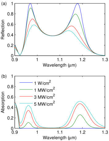
We now apply our validated nonlinear full-wave model [(Eq. (7)] to understand the role of nonlinear absorption in the dielectric metamaterial shown in Fig. 1(a). First, we studied the reflection and absorption for different incident intensities, shown in Fig. 5. For all intensities, the reflection spectrum contains narrowband peaks near 1.2 and 0.95 m, corresponding to the magnetic and electric dipole Mie resonances, respectively. For a low intensity of 1 W/cm2, the nonlinear processes are negligible, resulting in low absorption and nearly 100% reflection at the two resonances. As the intensity increases, the absorption at the resonances increases and the reflection decreases.
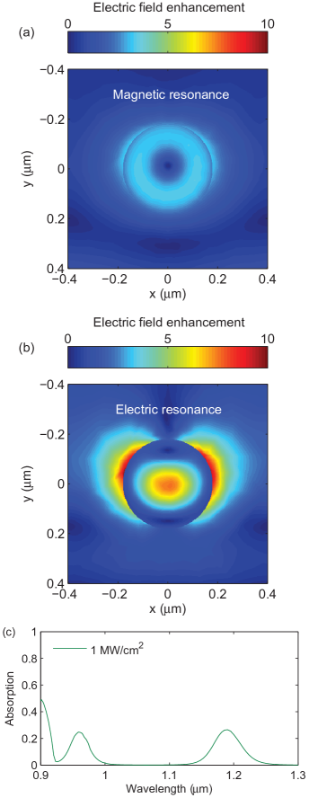
We note that for a given intensity, the absorption is larger at the magnetic resonance (1.2 m) than at the electric resonance (0.95 m). This is a surprising result considering the electric field distributions at the resonances, shown in Fig. 6(a) and (b) normalized to the incident electric field for an intensity of 1 MW/cm2. At the magnetic dipole resonance, the electric field is ring shaped and relatively uniform, while the electric field at the electric dipole resonance is highly concentrated at the center of the sphere. Note the field concentration outside the sphere arises from the boundary condition on the normal component electric field, which is discontinuous by the ratio of the dielectric constants of the sphere and free space Slovick et al. (2017). Thus, based on the field distributions, one might expect the absorption at the electric resonance to be larger due to the larger field concentration. However, we find more absorption at the magnetic resonance. We attribute this to the FCA cross section being about 5 times larger at the magnetic resonance than at the electric resonance [Fig. 3(b)]. To validate this claim, we recalculated the spectral absorption for 1 MW/cm2 intensity, assuming a constant FCA cross section. The results, shown in Fig. 6(c), show that the absorption is approximately equal at the two resonances, confirming that the wavelength-dependent FCA cross section is responsible for the larger absorption at the magnetic resonance. The fact that the absorption is equal at the two resonances for constant FCA is also counterintuitive, since more absorption is expected at the electric resonance because of the larger field concentration.
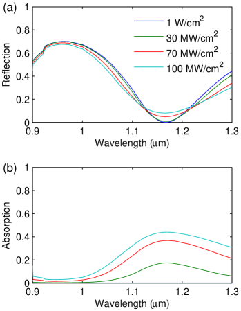
Since the electric field is enhanced at both resonances, we expect more absorption per unit length in the metamaterial than in a homogeneous material. To illustrate this, we calculated the reflection and absorption of a 360 nm-thick slab of InP, equal in thickness to the InP sphere metamaterial in Fig. 1(a). We see from Fig. 7 that 100 MW/cm2 of intensity is needed to obtain 40% absorption near 1.2 m in the homogenous layer, whereas the metamaterial obtains a similar level of absorption for 3 MW/cm2. Thus, the homogenous layer requires much higher intensities to achieve absorption values comparable to the metamaterial. This factor of 30 higher intensity is consistent with the five-fold field enhancement at the magnetic resonance shown in Fig. 6(a).
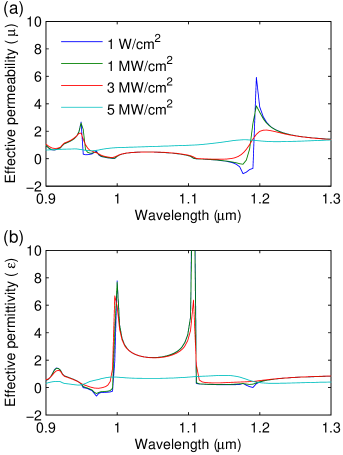
It is also important to understand the impact of nonlinear absorption on the effective permittivity () and permeability () of the metamaterial, as and are often used to obtain unique properties such as negative refraction Smith et al. (2000) and perfect reflection Slovick et al. (2013). The calculated real parts of and , shown in Fig. 8, were obtained using -parameter inversion, assuming a layer thickness of 1.24 m. At low intensities, shown as the blue line in Fig. 8(a), we see a strong resonance in near 1.2 m, which arises from the magnetic resonance. The weaker resonance near 0.95 m is the anti-resonance associated with the strong electric resonance at that wavelength, clearly seen in Fig. 8(b) for the permittivity. We also find a strong anti-resonance in at 1.1 m, which arises from the magnetic resonance at 1.2 m. These anti-resonances are an artifact of -parameter retrieval that arises from approximating a Bloch wave by a plane wave Koschny et al. (2003). In the resonance regions, either or is negative, resulting in single-negative regions and high reflectivity, as shown in Fig. 5(a). As the intensity increases to 1 MW/cm2 and 3 MW/cm2, we find that the magnetic resonance, near 1.2 m in Fig. 8(a), begins to dampen while the electric resonance, near 1 m in Fig. 8(b), is largely unchanged. Only when the intensity exceeds 3 MW/cm2 does the electric resonance begin to dampen. For 5 MW/cm2, both resonances are completely dampened. The dampening of the resonances with increasing intensity is also consistent with the decreasing reflection in Fig. 5(a). As the resonance in the real part of and broadens, the corresponding imaginary parts of and (not shown) also broaden, as per the Kramer-Kronig relationship, which results in broader-band absorption with increasing intensity, as shown in Fig. 5(b).
In summary, we developed a full-wave model to study the effects of two-photon absorption and photo-induced free-carrier absorption on the effective parameters and optical properties of a structured dielectric metamaterial operating in the near infrared spectral band. As expected, we find that nonlinear absorption leads to dampening of the electric and magnetic Mie resonances at high intensities, with an onset around 1 MW/cm2 for continuous wave illumination. The resonances are almost completely dampened for intensities around 5 MW/cm2. Surprisingly, we find that the nonlinear absorption at the magnetic resonance is larger than at the electric resonance, despite the electric field being more concentrated at the electric resonance. We find this is because the free-carrier absorption cross section is considerably larger at the longer wavelengths near the magnetic resonance. We also find that the metamaterial provides absorption comparable to a homogeneous layer of the same thickness at approximately 30 times less intensity. The lower threshold intensity and smaller footprint for nonlinear absorption can be exploited in applications involving optical limiting, frequency conversion, the Kerr effect, and four-wave mixing.
I Acknowledgement
This work was funded by the Office of Naval Research (ONR) through Contract No. N00014-16-C-1023
References
- Stryland et al. (1985) E. W. V. Stryland, H. Vanherzeele, M. A. Woodall, M. J. Soileau, A. L. Smirl, S. Guha, and T. F. Boggess, Opt. Eng. 24, 244613 (1985).
- Boggess et al. (1985) T. Boggess, A. Smirl, S. Moss, I. Boyd, and E. V. Stryland, IEEE J. Quant. Electron. 21, 488 (1985).
- Stryland et al. (1988) E. W. V. Stryland, Y. Y. Wu, D. J. Hagan, M. J. Soileau, and K. Mansour, JOSA B 5, 1980 (1988).
- Scalora et al. (1994) M. Scalora, J. P. Dowling, C. M. Bowden, and M. J. Bloemer, Phys.Rev. Lett. 73, 1368 (1994).
- Tran (1997) P. Tran, JOSA B 14, 2589 (1997).
- Hache and Bourgeois (2000) A. Hache and M. Bourgeois, Appl. Phys. Lett. 77, 4089 (2000).
- Rashkeev and Lambrecht (2001) S. N. Rashkeev and W. R. Lambrecht, Phys. Rev. B 63, 165212 (2001).
- Lekse et al. (2009) J. M. Lekse, M. A. Moreau, K. L. McNerny, J. Yeon, P. S. Halasyamani, and J. A. Aitken, Inorg. Chem. 48, 7516 (2009).
- Gallo and Assanto (1999) K. Gallo and G. Assanto, JOSA B 16, 267 (1999).
- Yu and Fan (2009) Z. Yu and S. Fan, Nat. Photon. 3, 91 (2009).
- Chang et al. (2014) D. E. Chang, V. Vuletic, and M. D. Lukin, Nat. Photon. 8, 685 (2014).
- Bechtel and Smith (1976) J. H. Bechtel and W. L. Smith, Phys. Rev. B 13, 3515 (1976).
- Boggess et al. (1986) T. Boggess, K. Bohnert, K. Mansour, S. Moss, I. Boyd, and A. Smirl, IEEE J. Quant. Electron. 22, 360 (1986).
- Krishnamurthy et al. (2011) S. Krishnamurthy, Z. G. Yu, L. P. Gonzalez, and S. Guha, J. Appl. Phys. 109, 033102 (2011).
- Kauranen and Zayats (2012) M. Kauranen and A. V. Zayats, Nat. Photon. 737, 6 (2012).
- Schuller et al. (2010) J. A. Schuller, E. S. Barnard, W. Cai, Y. C. Jun, J. S. White, and M. L. Brongersma, Nat. Mater. 9, 193 (2010).
- Czaplicki et al. (2013) R. Czaplicki, H. Husu, R. Siikanen, J. Makitalo, M. Kauranen, J. Laukkanen, J. Lehtolahti, and M. Kuittinen, Phys. Rev. Lett. 110, 093902 (2013).
- Aouani et al. (2012) H. Aouani, M. Navarro-Cia, M. Rahmani, T. P. Sidiropoulos, M. Hong, R. F. Oulton, and S. A. Maier, Nano Lett. 12, 4997 (2012).
- Thyagarajan et al. (2012) K. Thyagarajan, S. Rivier, A. Lovera, and O. J. Martin, Opt. Exp. 20, 12860 (2012).
- Thyagarajan et al. (2013) K. Thyagarajan, J. Butet, and O. J. Martin, Nano Lett. 13, 1847 (2013).
- Zhang et al. (2011) Y. Zhang, N. K. Grady, C. Ayala-Orozco, and N. J. Halas, Nano Lett. 11, 5519 (2011).
- Harutyunyan et al. (2012) H. Harutyunyan, G. Volpe, R. Quidant, and L. Novotny, Phys. Rev. Lett. 108, 217403 (2012).
- Navarro-Cia and Maier (2012) M. Navarro-Cia and S. A. Maier, ACS Nano 6, 3537 (2012).
- Gu et al. (2012) J. Gu, R. Singh, X. Liu, X. Zhang, Y. Ma, S. Zhang, S. A. Maier, Z. Tian, A. K. Azad, H. T. Chen, and A. J. Taylor, Nat. Comm. 3, 1151 (2012).
- Kurter et al. (2011) C. Kurter, P. Tassin, L. Zhang, T. Koschny, A. P. Zhuravel, A. V. Ustinov, S. M. Anlage, and C. M. Soukoulis, Phys. Rev. Lett. 107, 043901 (2011).
- Shcherbakov et al. (2014) M. R. Shcherbakov, D. N. Neshev, B. Hopkins, A. S. Shorokhov, I. Staude, E. V. Melik-Gaykazyan, M. Decker, A. A. Ezhov, A. E. Miroshnichenko, I. Brener, and A. A. Fedyanin, Nano Lett. 14, 6488 (2014).
- Yang et al. (2015) Y. Yang, W. Wang, A. Boulesbaa, I. I. Kravchenko, D. P. Briggs, A. Puretzky, D. Geohegan, and J. Valentine, Nano Lett. 15, 7388 (2015).
- Kapitanova et al. (2017) P. Kapitanova, V. Ternovski, A. Miroshnichenko, N. Pavlov, P. Belov, Y. Kivshar, and M. Tribelsky, Sci. Rep. 7, 731 (2017).
- Shcherbakov et al. (2015a) M. R. Shcherbakov, A. S. Shorokhov, D. N. Neshev, B. Hopkins, I. Staude, E. V. Melik-Gaykazyan, A. A. Ezhov, A. E. Miroshnichenko, I. Brener, A. A. Fedyanin, and Y. S. Kivshar, ACS Photon. 2, 578 (2015a).
- Smirnova et al. (2016) D. A. Smirnova, A. B. Khanikaev, L. A. Smirnov, and Y. S. Kivshar, ACS Photon. 3, 1468 (2016).
- Grinblat et al. (2016) G. Grinblat, Y. Li, M. P. Nielsen, R. F. Oulton, and S. A. Maier, Nano Lett. 16, 4635 (2016).
- Shorokhov et al. (2016) A. S. Shorokhov, E. V. Melik-Gaykazyan, D. A. Smirnova, B. Hopkins, K. E. Chong, D. Y. Choi, M. R. Shcherbakov, A. E. Miroshnichenko, D. N. Neshev, A. A. Fedyanin, and Y. S. Kivshar, Nano Lett. 16, 4857 (2016).
- Shcherbakov et al. (2015b) M. R. Shcherbakov, P. P. Vabishchevich, A. S. Shorokhov, K. E. Chong, D. Choi, I. Staude, A. E. Miroshnichenko, D. N. Neshev, A. A. Fedyanin, and Y. S. Kivshar, Nano Lett. 15, 6985 (2015b).
- Makarov et al. (2015) S. Makarov, S. Kudryashov, I. Mukhin, A. Mozharov, V. Milichko, A. Krasnok, and P. Belov, Nano Lett. 15, 6187 (2015).
- Baranov et al. (2016) D. G. Baranov, S. V. Makarov, V. A. Milichko, S. I. Kudryashov, A. E. Krasnok, and P. A. Belov, ACS Photon. 3, 1546 (2016).
- Weismann et al. (2015) M. Weismann, D. F. Gallagher, and N. C. Panoiu, JOSA B 32, 523 (2015).
- Weismann and Panoiu (2016) M. Weismann and N. C. Panoiu, Phys. Rev. B 94, 035435 (2016).
- Kruk et al. (2015) S. Kruk, M. Weismann, A. Y. Bykov, E. A. Mamonov, I. A. Kolmychek, T. Murzina, N. C. Panoiu, D. N. Neshev, and Y. S. Kivshar, ACS Photon. 2, 1007 (2015).
- Shen (1984) Y. R. Shen, The principles of nonlinear optics (Wiley-Interscience, 1984).
- Stegeman and Stegeman (2012) G. I. Stegeman and R. A. Stegeman, Nonlinear Optics: Phenomena, Materials and Devices (Vol. 78) (John Wiley & Sons, 2012).
- Slovick et al. (2017) B. A. Slovick, Y. Zhou, Z. G. Yu, I. I. Kravchenko, D. P. Briggs, P. Moitra, S. Krishnamurthy, and J. Valentine, Phil. Trans. R. Soc. A 375, 0072 (2017).
- Smith et al. (2000) D. R. Smith, W. J. Padilla, D. C. Vier, S. C. Nemat-Nasser, and S. Schultz, Phys. Rev. Lett. 84, 4184 (2000).
- Slovick et al. (2013) B. Slovick, Z. G. Yu, M. Berding, and S. Krishnamurthy, Phys. Rev. B. 88, 165116 (2013).
- Koschny et al. (2003) T. Koschny, P. Markos, D. R. Smith, and C. M. Soukoulis, Phys. Rev. E 68, 065602 (2003).