Atomic Structure of Domain and Interphase Boundaries in Ferroelectric HfO2
Abstract
Though the electrical responses of the various polymorphs found in ferroelectric polycrystalline thin film HfO2 are now well characterized, little is currently understood of this novel material’s grain sub-structure. In particular, the formation of domain and phase boundaries requires investigation to better understand phase stabilization, switching, and interconversion. Here, we apply scanning transmission electron microscopy to investigate the atomic structure of boundaries in these materials. In particular, we find orthorhombic/orthorhombic domain walls and coherent orthorhombic/monoclinic interphase boundaries formed throughout individual grains. The results inform how interphase boundaries can impose strain conditions that may be key to phase stabilization. Moreover, the atomic structure near interphase boundary walls suggests potential for their mobility under bias, which has been speculated to occur in perovskite morphotropic phase boundary systems by mechanisms similar to domain boundary motion.
Institute of Semiconductors and Microsystems, TU Dresden D-01062 Dresden, Germany
1 Introduction
Following the first report of its ferroelectric behavior,research on hafnia (HfO2) systems has continued with renewed interest 1. This is spurred on by its robust, lead-free ferroelectric properties that are maintained even in films thinner than 10 nm. Because of its silicon compatibility and wide processing space, the material shows promise for use in future memories 2, 3, energy efficient logic transistors 4, 5, and devices that exploit a tunable dielectric 6 or pyroelectric 7, 8, 9.
As understanding of ferroelectricity in hafnia develops, grain sub-structure is proving increasingly important for controlling film properties. While bulk hafnia is known to adopt the P/c monoclinic phase (M) at room temperature and pressure 10, “metastable” high symmetry fluorite-like phases including P/nmc tetragonal (T) and orthorhombic (O) phases can coexist in the ferroelectric thin films 1, 2, 11, 12, 9, 13. An orthorhombic phase Pca21 that lacks an inversion center is thought to be responsible for the ferroelectric behavior of these thin films, and has been observed with scanning transmission electron microscopy (STEM) 11, 14. Electron microscopy has also revealed interfacial hafnia regions exhibiting tetragonal-like symmetry at electrode/bulk grain interfaces in moderately doped films 15, 16, 12, and its presence dominates at high dopant concentrations 13, 12. Critically, the net electrical behavior is strongly governed by the fractions of each phase in a given device 17, 12, 13.
First-principles calculations suggest that various forces contribute to stabilizing the different distorted fluorite phases of HfO2, enabling ferroelectric switching, and/or possibly allowing phase transformation. These include electric fields 18, 19, surface energies 18, 20, strain from different origins 21, 18, 19, 22, and alloying 18. Experiment and theory point to an orthorhombic switching pathway through the tetragonal phase 2, 23, 21, 22, and in certain instances the tetragonal-to-orthorhombic transition might be transient during the application of an electric field 3.
Recently, studies have also highlighted the structural similarities between the orthorhombic and monoclinic phases 24, 22. Barabash et al. report that differences in oxygen ordering in a “parent” orthorhombic phase (centrosymmetric Pbcm) can lead to stabilization of either the monoclinic or the polar orthorhombic phase. Furthermore, they speculate that a region of coherently strained HfO2 lacking the monoclinic distortion might readily convert between the monoclinic and polar orthorhombic phase via a low transformation barrier 22. Experimental evidence also suggests that some amount of phase transformation may occur during the “wake-up” effect 25, 26, 27, 15, 16. The complexities of characterizing polycrystalline and polyphasic hafnia thin films have, however, limited current information of phase distribution, coexistence, and domain structuring in this new ferroelectric system.
Internal boundaries are also crucial to consider as they can impact a ferroelectric material’s mechanical and electrical response. This has been seen, for example, near morphotropic phase boundaries (MPBs) in the phase diagrams of certain materials. Pb(Zr,Ti)O3 exhibits coexistence of polar rhombohedral and polar tetragonal phases, which exist in fractions and over length scales that depend largely on the composition 28. Domain wall energy is an important parameter for determining the length scale of ordering and the domain sizes, and thus has important implications for mechanical and electrical behavior 29. Because these systems contain multiple phases, “interphase boundaries” can form as walls between different phases. Furthermore, mobile interphase boundaries are speculated to move during cycling in small reversible and irreversible jumps like domain walls 30, 31, 32. The presence of interphase boundaries in ferroelectric hafnia would thus be expected to influence its phase stability through internal strains at immobile boundaries, and its electrical properties in the case of those that are mobile which would contribute to changes in phase fractions.
In this article, interphase boundaries and single phase domains in Gd doped HfO2 metal-ferroelectric-metal capacitors are studied using aberration corrected scanning transmission electron microscopy (STEM). Monoclinic, orthorhombic, and tetragonal regions are found to coexist within single grains, and the presence of domain walls in the orthorhombic phase are correlated to field-cycling history. Monoclinic/orthorhombic interphase boundaries are revealed and analyzed in the context of the structural parameters that govern their formation. Moreover, our results highlight the similarities between the orthorhombic and monoclinic phases. These similarities lead to challenges in distinguishing a “defect” in one phase from the “normal” structure of the other phase. These combined results suggest that the environments near interphase boundaries lead to the formation of new orthorhombic regions. Contingent on the stability/mobility of these boundaries, such boundaries are proposed to facilitate some degree of phase conversion under electrical bias.
2 Results and Discussion
HfO2 grains typically span the thickness of the film between the TiN electrodes, as shown by the bright grain spanning the distance between the two dark electrodes in Figure 1a. Using high-angle annular dark-field (HAADF) STEM, the identity and orientation of phases in HfO2 films are readily determined using the atomically resolved positions of the projected Hf atom sub-lattice 11, 16. This analysis reveals that certain grains exhibit a complex domain structure. For example, a single grain is divided into two orthorhombic (O1, O2) and one monoclinic (M1) region in Figure 1a. At the O1/O2 boundary in Figure 1c, in O1 are parallel to in O2, where are continuous across the domain wall. The boundary between the two regions is sharp and possesses an abrupt change in projected symmetry at the domain wall. This symmetry change is made more visible by inspection of the atom column near neighbor distances, which are mapped in Figure 1d. An interphase boundary is also observed within the same grain (see Figure 1e), where the crystal structure abruptly transitions from O2 to M1 with .
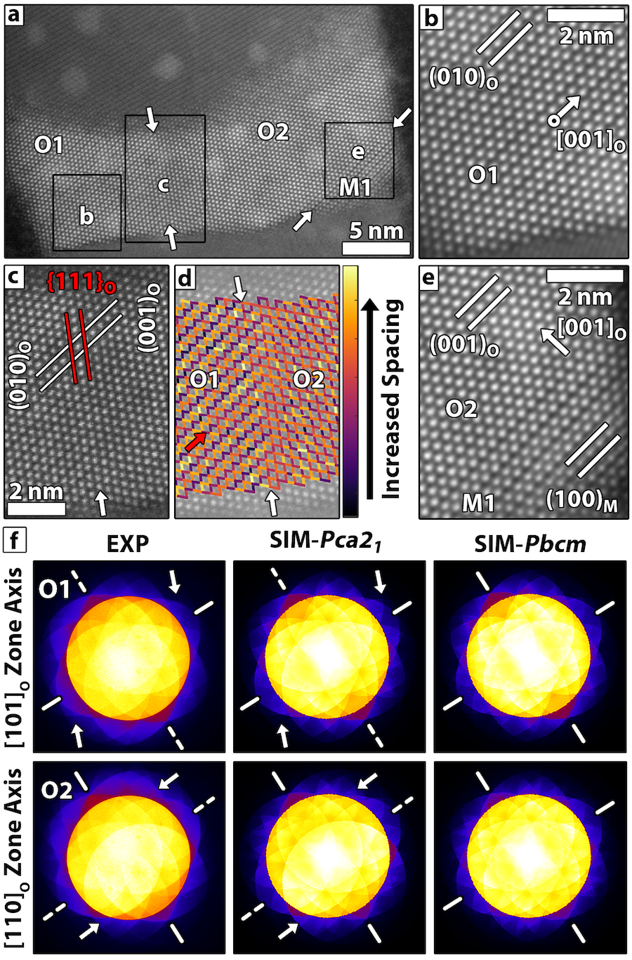
Connecting structure to polarization is essential for understanding the ferroelectric behavior of HfO2 thin films. Polarization across the O1/O2 domain wall can be assessed by position-averaged convergent beam electron diffraction (PACBED), where missing mirror symmetry in the pattern corresponds to a lack of inversion symmetry in the material 33, 11. This occurs for the Pca21 orthorhombic phase along the , and is indicated by arrows in Figure 1b,e (note that the in Figure 1b possesses a component out of the image plane). Figure 1f shows PACBED patterns acquired from regions O1 and O2. Each pattern lacks a mirror plane across the dashed axis bisecting the pattern, which is consistent with the Pca21 polar phase simulations. In contrast, simulated patterns from the centrosymmetric Pbcm phase retain mirror symmetry along both axes. These results show that the polar direction is rotated by , hence forming a 90∘ domain wall.
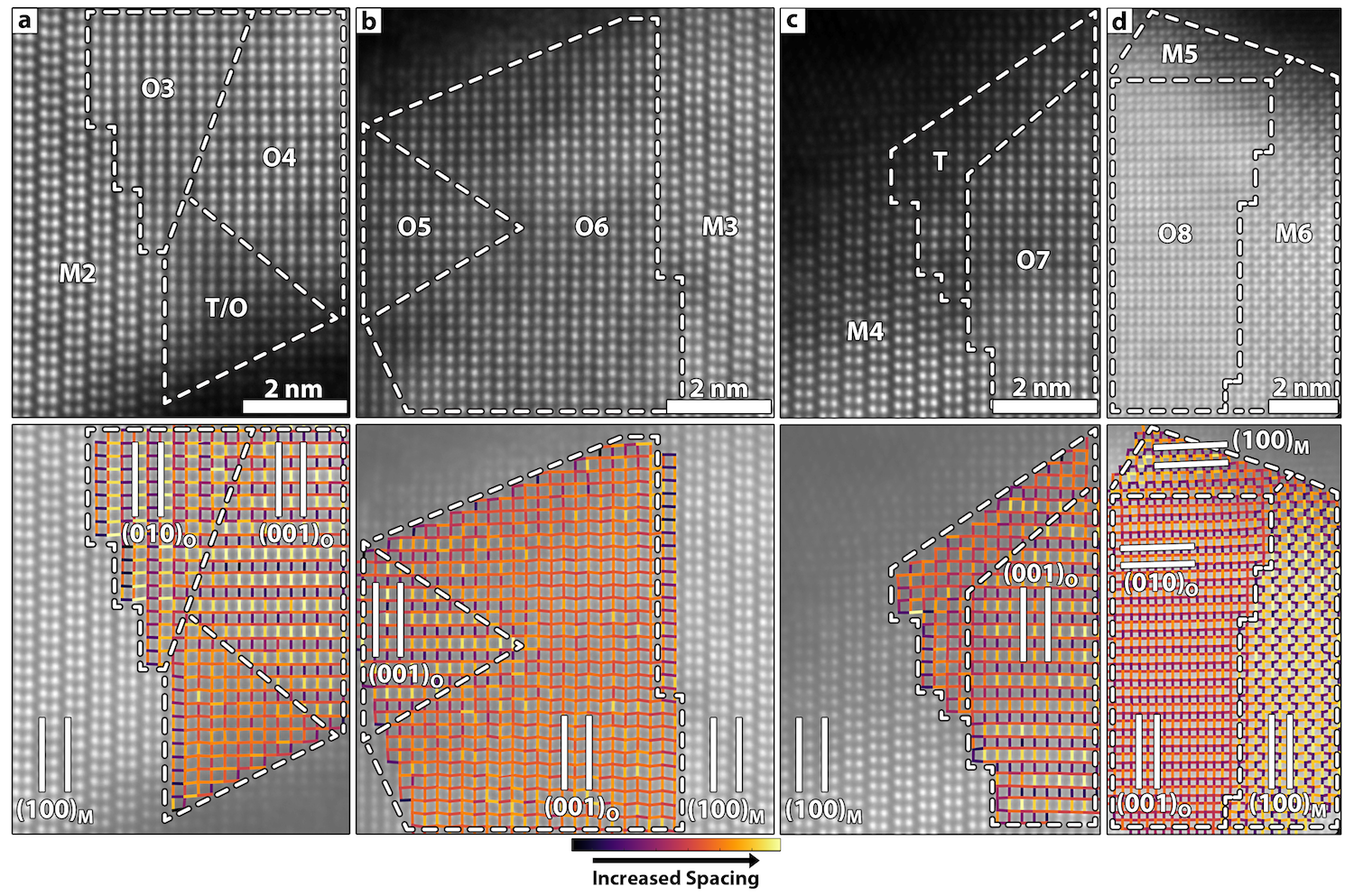
More broadly, a wide range of interphase and domain boundaries are observed throughout the sample as highlighted by Figure 2a-d. The images reveal several O/O domains and O/M interphase boundary structures in a variety of shapes and sizes. Changes in atom column spacing and symmetry across the boundaries are highlighted by near neighbor distance maps in the bottom panels of Figure 2a-d. While some boundaries are angular and difficult to precisely locate, others are flat with fractional unit-cell steps. Figure 2a shows a typical 90∘ domain between orthorhombic regions O3 and O4. As in the case of the O1/O2 boundary in Figure 1c, becomes across the O3/O4 domain wall. The transition in crystal symmetry is abrupt, and like the O1/O2 boundary, occurs over a higher order crystal plane. Not all boundary transitions are sharp in the vicinity of 90∘ domain walls. For example, Figure 2b shows a 90∘ domain wall formed at the interface between regions O5 and O6. Unlike the O/O domains in Figures 1c and 2a, of this domain remain parallel across the boundary and instead rotate 90∘ in-plane.
Based on the domain walls presented in Figures 2a-b, which are viewed down low order zone axes, some aspects of the structure of orthorhombic domain boundaries can be linked to misfit. As reported in Ref. 11, the lattice parameters of the orthorhombic structure are ao,bo,co = 5.24, 5.06, 5.07 Å, which results in a 0.2 % misfit across the O3/O4 domain wall and a rather abrupt change in rotation across the boundary. In contrast, the O5/O6 boundary exhibits high misfit of 3.5%, and possesses a much more diffuse transition in structure across the boundary. This likely arises due to the larger misfit and/or grain overlap. The three examples of orthorhombic domains in Figures 1c and 2a-b exemplify how local environments allow domains to form in a variety of orientations, sizes/shapes, and domain wall configurations.
The monoclinic phase is found to form twin boundaries in some grains. For example, a twin in Figure 2d is identified between the monoclinic regions M5 and M6. Twining also occurs on (Supporting Information, Figure S1a) and (Supporting Information, Figure S1b). These twin planes are in good agreement with various reports of twinning configurations identified in toughened zirconia ceramics 34, HfO2 thin films grown directly on Si 35, and in Hf-rich HfxZr1-xO2 nanocrystals 36. Twinning is associated with the tetragonal to monoclinic martensitic phase transformation 34, 36, 35, 37. Such a phase transformation requires a shape change to the distorted monoclinic cell, and twinning is a mechanism whereby shape change/shear strain can be minimized for the transformation of a confined grain 34.
Figure 2a-d also shows that many HfO2 regions contain interphase boundaries. In Figure 2a, an interphase boundary between M2/O3 regions forms with an interface with . The interphase boundary wall is discontinuous, with steps forming every few nanometers. Strain near the wall results in visible distortion of the spacing and angle between atom columns in the vicinity of the boundary, as seen in the Figure 2a distance map. Similarly, the structures become blurred adjacent to the boundary wall, which can indicate phase overlap or non-uniform lattice distortion near the boundary. Furthermore, the M4/O7 boundary in Figure 2c forms an interface with , and where lattice distortion visible in the vicinity of the interface. Visually, the M4/O7 interphase boundary resembles the M2/O3 boundary, but the orthorhombic region is rotated 90∘ such that forms the boundary rather than .
In addition to the M/O boundaries in Figure 2a,c mixed tetragonal/orthorhombic symmetry is observed near the TiN electrodes. Interfacial hafnia layers near TiN electrodes are previously reported to relax towards tetragonal symmetry in some instances 16. We propose that these these current findings indicate the local environment near an interphase boundary can promote the stabilization of the tetragonal phase deeper into the grain bulk to 2-4 nm. Transition regions with mixed/strained symmetry like the tetragonal interface layers reported earlier can be important for phase stabilization 38.
The interphase boundaries in Figures 2b,d have reduced step density compared to those in Figures 2a,c. For example at the O6/M3 interface in Figure 2b, an abrupt interphase boundary is formed with . The transition in crystal symmetry from orthorhombic to monoclinic is sharp in this case, having less distortion. Further, the boundary between the O8/M5 regions shows no clear steps between the planes that form the wall in Figure 2d. A second boundary in this region also forms between O8/M6 regions with , with varied step density. Furthermore, the O6/M3 and O8/M6 interphase boundaries are equivalent, though they are viewed along different crystal projections.
Based on these observations interphase boundaries are expected to traverse complicated, three dimensional paths through the grain. The nature of the final domain wall thus depends on the size and orientation of the regions that form during annealing. Furthermore, some of the distortion visible near the domain walls is likely the result of viewing a projection of the three-dimensional domain wall structure.
The library of observed interphase boundaries gives insight into how crystal chemistry may influence their formation. The examples of interphase boundaries in Figures 1 and 2 suggests that the monoclinic and orthorhombic phases tend to form coherent boundaries across low order planes in polycrystalline hafnia thin films. This is consistent with phase boundaries seen in strained epitaxial (Hf,Zr)O2 thin films 39. Additionally, the boundary step structure suggests a role of misfit in determining their periodicity. The misfit here is defined as the difference in lattice parameters divided by their average. For example, the greatest possible uniaxial misfit occurs at O/M boundaries where the cm axis of the monoclinic phase (cm= 5.30 Å) aligns to either the orthorhombic bo axis (4.6 % misfit) or co axis (4.4 % misfit), where co = 5.07 Å and bo = 5.06 Å. These boundaries with maximum misfit still form and readily step as seen in Figure 2a,c. Comparatively, when O/M boundaries form such that the ao and cm axes are parallel, misfit is significantly reduced to 2.0 % when bm/co and 2.2 % when bm/bo, where bm = 5.17 Å. These lower misfit boundaries subsequently contain fewer steps as seen in Figure 2b,d.
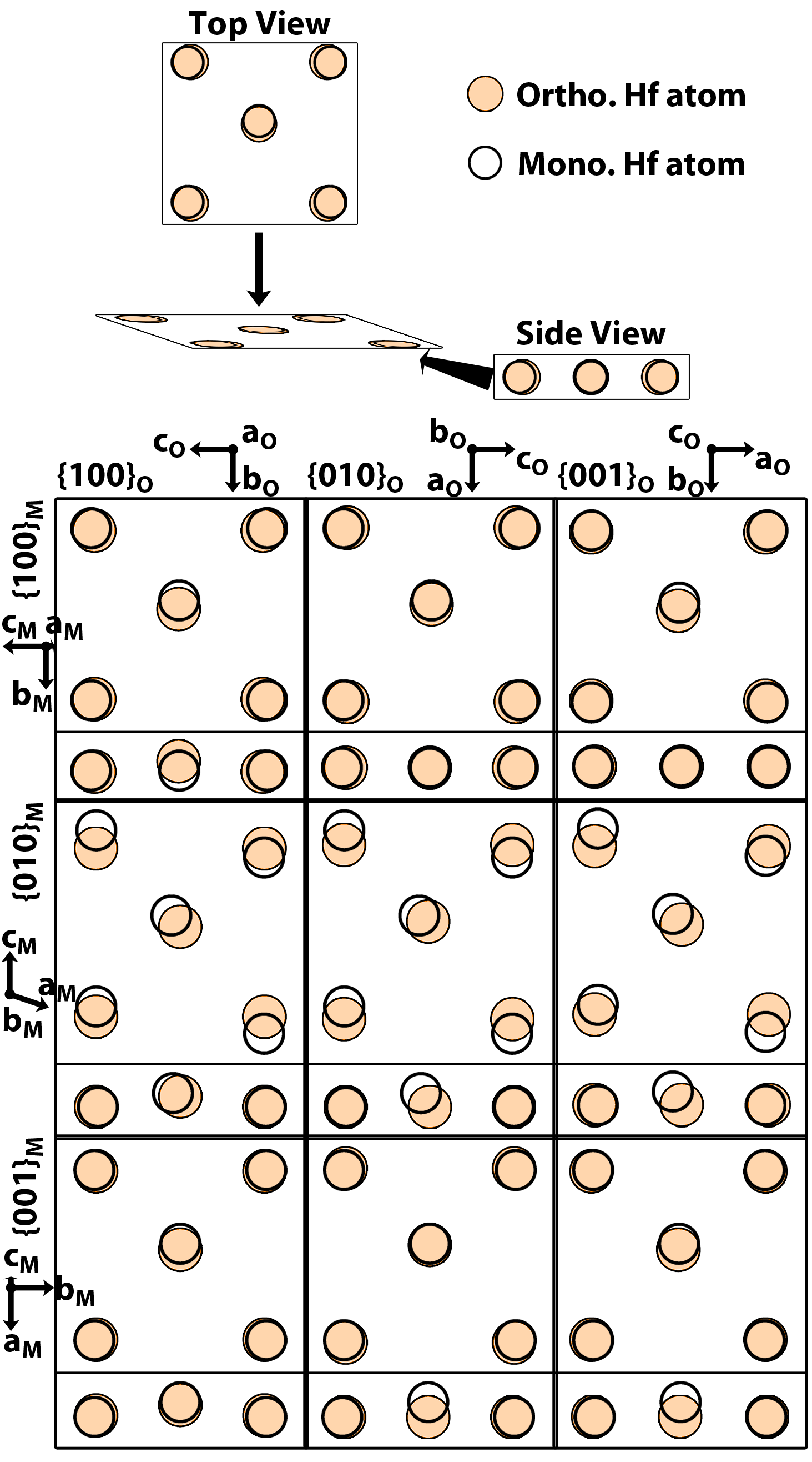
Figure 3 shows structural schematics of an interfacial plane, focusing on the Hf positions. Only a single variant of the boundary is shown here, i.e. rotating the orthorhombic lattice in-plane by 90∘ will change the interface orientation, strain, and alignment of the atoms. Because the is non-orthogonal ( = 99.18∘), there is relatively poor registration to all orthorhombic planes. In contrast, the set of boundaries formed with and provide reasonable registry with the low order orthorhombic planes.
Both orthorhombic and monoclinic cells possess reduced symmetry involving lateral and out-of-plane shifts in atom positions. When viewed from the side, Figure 3, the Hf sub-lattice remains co-planar for the , , and , while it is rumpled out-of plane for , , and . Based on these observations, interphase boundaries tend to form in orientations that maintain a co-planar Hf sub-lattice across the boundary, i.e. without out-of-plane rumpling. Furthermore, the local Hf-O bonding configuration across the boundary may also play a role. Furthermore, this finding is in good qualitative agreement with studies that show the habit is the more favorable habit planes for related zirconia phase transformations 41. Strain and displacements of the Hf sub-lattice needed to form certain rumpled boundaries (i.e. any boundaries with the plane) do not appear dramatically different than that of the observed boundaries, and so cannot be ruled out entirely.
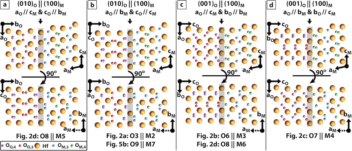
Approximate configurations of the structures observed at interphase boundaries are provided in Figure 4. The shaded terminal Hf plane at the boundaries are those of the orthorhombic phase. Note that both phases have three-coordinate and four-coordinate oxygen atom positions. Because the oxygen sub-lattices are not observed in the STEM images, the schematics are approximate and represent one of several possible configurations. Nonetheless, the boundaries show how O/M boundaries can form that reasonably satisfy the symmetry of both phases.
The variety of observed interphase boundaries provides insight into how they might influence phase stabilization and enable phase transformation. Immobile boundaries artificially limit the grain size and impart a coherent strain onto the lattices, which is known to play an important role in phase stabilization 18, 19, 22. Furthermore, these boundaries can influence domain pinning. A boundary capable of moving under the influence of an electric field would alter the electrical behavior by changing the phase fractions during cycling. For example, monoclinic/orthorhombic phase transformations have been initiated during electron beam irradiation in both zirconia particles 42 and ceramics 43. While the boundaries observed here did not move during STEM imaging, identical boundary orientations exhibit several different configuration.
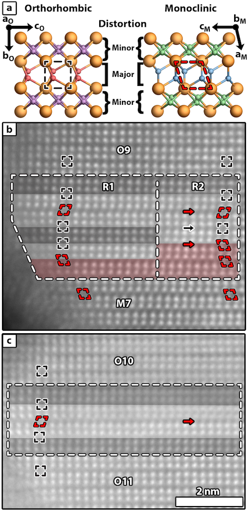
With respect to boundary mobility, Figure 5b is instructive. This boundary is oriented equivalently to ones previously shown to be mobile in particles of the related zirconia crystal structure 42. This boundary also displays many unique features that set it apart from the similar boundary presented earlier in Figure 2a. Distinct orthorhombic O9 and monoclinic M7 regions are separated by a complicated interphase boundary, which is segmented into regions R1 and R2 by the dotted lines within the boundary region in Figure 5a. The qualitative symmetry of the Hf sub-lattice is indicated by colored overlays with black indicating pure orthorhombic symmetry, red representing pure monoclinic symmetry, and white labeling regions where the Hf sub-lattice seemingly co-satisfies the symmetry of each phase.
The monoclinic and orthorhombic unit-cells can be thought of as distorted tetragonal unit-cells 44. Half the the structure resembles, with minor distortion, the parent tetragonal phase, while the other half deviates significantly for both monoclinic and orthorhombic cells, see Figure 5a. The layers with minor distortions are structurally very similar between the monoclinic and orthorhombic phases. By contrast, the majority of the differences between the monoclinic and orthorhombic phase occur within the major distortion layers.
The nominal structures of the major distortion layers are labeled in Figure 5b. Several interesting structural features occur in this boundary. First, the bottom red arrow in R2 indicates a monoclinic-like major distortion layer that becomes an orthorhombic-like major distortion layer across the R2/R1 boundary. Next, the monoclinic major distortion layer at the same red arrow appears “twinned” with respect to the monoclinic major distortion layer indicated by the top red arrow. This twin-like feature occurs across a major distortion layer resembling the orthorhombic phase (black arrow). The monoclinic-like major distortion layer indicated by the top red arrow occurs between two major distortion units with orthorhombic-like structures. From this analysis, it becomes apparent that substitution of a monoclinic-like major distorted layer into an orthorhombic lattice results in an anti-phase-like boundary in the orthorhombic phase (see top red arrow in Figure 5b and red arrow in Figure 5c). Similarly, insertion of an orthorhomibic-like major distortion layer into the monoclinic lattice results in a “twin-like” defect (see black arrow in Figure 5b).
The large variation in the structure at these boundaries hints at the potential for mobility during the application of an electric field. Specifically, the “snapshot” in Figure 5b suggests an interphase boundary in various states of converting between the monoclinic and orthorhombic lattices, much as suggested by the “step-flow”-like motion of the same boundary orientation in Ref. 42. Crystal chemistry suggests a double glide system that converts the orthorhombic phase into the monoclinic phase, with the reverse occurring by a double glide 44. Such glides impact the symmetry of the entire unit-cell, though a majority of the structural changes occur within the more major distortion portions of the unit cells 44. Consistent with this, the structure of the major distortion layer indicated by the bottom red arrow transitions between glide states at the boundary between regions R2 and R1. Furthermore, this glide system explains how insertion of one phase’s major distortion structure into the other phase initiates features akin to “anti-phase-like” and “twin-like” defects, as discussed above.
Consistent with the understanding that some interphase boundaries are likely immobile in ferroelectric hafnia, M/O interphase boundaries are still observed after field-cycling, of which Figure 5b-c is such an example. Internal discontinuities and strains as encountered near interphase boundaries are important for phase stabilization as they limit grain size and exert an internal force. Domain boundaries have been suggested as stabilizing higher symmetry phases in zirconia nanoparticles 45, and interphase boundaries can play a similar role in this system. Phase stability can change in the vicinity of interphase boundaries due to differences in local epitaxial strain 18, 19, 22, or even due to a departure from the undistorted monoclinic and orthorhombic lattices 24, 22. In these instances, application of an electric field may be insufficient to destabilize one phase with respect to one another. Such boundaries would also play a role in fatigue mechanisms in these materials.
Unlike the M/O interphase boundaries, no clear examples of 90∘ domains in the orthorhombic phase are found in the current work for field-cycled samples. Within the limits of the STEM sampling, this suggests that field-cycling results in increased domain uniformity by aligning some of the “as-grown” 90∘ domains. Such an increase in domain uniformity would concomitantly increase the remanent polarization, which is observed during wake-up when field cycling 46, 15, 16. Moreover, martensitic phase changes between high symmetry phases and the non-orthogonal monoclinic phase necessitates a shape change. This has been seen in the case of both orthorhombic zirconia particles 42 and tetragonal hafnia-zirconia nanoparticles 36. Twin formation in the monoclinic phase has been shown to minimize shear strain during such a transformation for both hafnia-zirconia nanoparticles 36 and hafnia thin films 35. Due to a restricted geometry, thin films have fewer degrees of freedom by which to change shape, and likely rely more on generation of accommodating defects like dislocations and twin and/or anti-phase boundaries to convert between phases. Moreover, the shear strains required for such a transformation may be inaccessible to certain regions of the sample, locking in a higher symmetry phase 35. As such, the geometric constraints due to electrode(s), neighboring grain(s), and/or other boundaries may immobilize some of the interphase boundaries with little to no room to move around their eccentric positions.
3 Conclusions
This work demonstrates the rich structural chemistry accessible to ferroelectric HfO2, which enables formation of a complex mixture of domains, planar defects, and interphase boundaries. The complex structure near interphase boundaries hints at a possible continuum between orthorhombic and monoclinic phases in the vicinity of the boundary walls. Further, the distortions present near these boundaries suggests the potential for mobility. These insights yield new perspectives for the modeling of switching and domain wall motion, and provide a basis for comparison to domain wall and interphase boundaries in conventional perovskite ferroelectrics. Overall, this work lays the groundwork for calculations aiming to explore interphase boundary energetics, where further knowledge is needed to improve stability, mobility, and their impact of field-cycling.
4 Methods
4.1 Sample Information
27 nm Gd:HfO2 capacitors with 10 nm TiN electrodes were grown using atomic layer deposition as described previously 47. Lamella were prepared for scanning transmission electron microscopy (STEM) by focused ion beam from both cycled and pristine devices using an FEI Quanta. Details of the field cycling can be found in Ref. 16.
4.2 Scanning Transmission Electron Microscopy
High-angle annular dark-field (HAADF) STEM was performed on an FEI Titan G2 60-300 kV equipped with a probe-corrector and an X-FEG source. The microscope was operated at 200 kV with a detector inner semi-angle of approximately 77 mrad, probe currents of around 80 pA measured with the current monitor on the screen, and probe semi-convergence angle approximately equal to 19.6 mrad. RevSTEM images 48 were acquired using 40 1024 x 1024 pixel frames with a 2 s/pixel dwell time and a 90∘ rotation between each successive frame. Where necessary, scan coil distortion was removed by previously described methods 49. The atom column positions were determined by fitting two-dimensional Gaussian distributions via MATLAB scripting 50. PACBED patterns were simulated using the MBFIT (“Many-Beam dynamical-simulations and least-squares FITting”) package by K. Tsuda at Tohoku University 51. Simulation parameters matched those from experiment. Structural parameters were taken from Refs. 40, 52, 53, 11. The simulation output was rescaled using bicubic interpolation to match experiment.
Christoph Adelmann from Imec, Belgium is gratefully acknowledged for depositing the TiN-Gd:HfO2-TiN stacks. The authors thank Jacob L. Jones for helpful feedback and discussions. EDG and JML gratefully acknowledge support from the National Science Foundation (Award No. DMR-1350273). EDG acknowledges support for this work through a National Science Foundation Graduate Research Fellowship (Grant DGE-1252376). TS, US and TM gratefully acknowledge the German Research Foundation (Deutsche Forschungsgemeinschaft) for funding part of this research in the frame of the “Inferox” project (MI 1247/11-2). This work was performed in part at the Analytical Instrumentation Facility (AIF) at North Carolina State University, which is supported by the State of North Carolina and the National Science Foundation (award number ECCS-1542015). The AIF is a member of the North Carolina Research Triangle Nanotechnology Network (RTNN), a site in the National Nanotechnology Coordinated Infrastructure (NNCI). \suppinfo
References
- Böscke et al. 2011 Böscke, T. S.; Müller, J.; Bräuhaus, D.; Schröder, U.; Böttger, U. Ferroelectricity in hafnium oxide thin films. Applied Physics Letters 2011, 99, 102903
- Müller et al. 2012 Müller, J.; Böscke, T. S.; Schröder, U.; Mueller, S.; Bräuhaus, D.; Böttger, U.; Frey, L.; Mikolajick, T. Ferroelectricity in Simple Binary ZrO2 and HfO2. Nano Letters 2012, 12, 4318–4323
- Pešić et al. 2016 Pešić, M.; Hoffmann, M.; Richter, C.; Mikolajick, T.; Schroeder, U. Nonvolatile Random Access Memory and Energy Storage Based on Antiferroelectric Like Hysteresis in ZrO2. Advanced Functional Materials 2016, 26, 7486–7494
- Mulaosmanovic et al. 2015 Mulaosmanovic, H.; Slesazeck, S.; Ocker, J.; Pesic, M.; Muller, S.; Flachowsky, S.; M ller, J.; Polakowski, P.; Paul, J.; Jansen, S. et al. Evidence of single domain switching in hafnium oxide based FeFETs: Enabler for multi-level FeFET memory cells. 2015 IEEE International Electron Devices Meeting (IEDM). 2015; pp 26.8.1–26.8.3
- Hoffmann et al. 2016 Hoffmann, M.; Pešić, M.; Chatterjee, K.; Khan, A. I.; Salahuddin, S.; Slesazeck, S.; Schroeder, U.; Mikolajick, T. Direct Observation of Negative Capacitance in Polycrystalline Ferroelectric HfO2. Advanced Functional Materials 2016, 26, 8643–8649
- Dragoman et al. 2017 Dragoman, M.; Aldrigo, M.; Modreanu, M.; Dragoman, D. Extraordinary tunability of high-frequency devices using Hf0.3Zr0.7O2 ferroelectric at very low applied voltages. Applied Physics Letters 2017, 110, 103104
- Hoffmann et al. 2015 Hoffmann, M.; Schroeder, U.; Künneth, C.; Kersch, A.; Starschich, S.; Böttger, U.; Mikolajick, T. Ferroelectric phase transitions in nanoscale HfO2 films enable giant pyroelectric energy conversion and highly efficient supercapacitors. Nano Energy 2015, 18, 154–164
- Park et al. 2016 Park, M. H.; Kim, H. J.; Kim, Y. J.; Moon, T.; Kim, K. D.; Lee, Y. H.; Hyun, S. D.; Hwang, C. S. Giant Negative Electrocaloric Effects of Hf0.5Zr0.5O2 Thin Films. Advanced Materials 2016, 28, 7956–7961
- Smith et al. 2017 Smith, S. W.; Kitahara, A. R.; Rodriguez, M. A.; Henry, M. D.; Brumbach, M. T.; Ihlefeld, J. F. Pyroelectric response in crystalline hafnium zirconium oxide (Hf1-xZrxO2) thin films. Applied Physics Letters 2017, 110, 072901
- Adams et al. 1991 Adams, D. M.; Leonard, S.; Russell, D. R.; Cernik, R. J. X-ray diffraction study of Hafnia under high pressure using synchrotron radiation. Journal of Physics and Chemistry of Solids 1991, 52, 1181–1186
- Sang et al. 2015 Sang, X.; Grimley, E. D.; Schenk, T.; Schroeder, U.; LeBeau, J. M. On the structural origins of ferroelectricity in HfO2 thin films. Applied Physics Letters 2015, 106, 162905
- Richter et al. 2017 Richter, C.; Schenk, T.; Park, M. H.; Tscharntke, F. A.; Grimley, E. D.; LeBeau, J. M.; Zhou, C.; Fancher, C. M.; Jones, J. L.; Mikolajick, T. et al. Si Doped Hafnium Oxide - A “Fragile” Ferroelectric System. Advanced Electronic Materials (accepted) 2017,
- Park et al. 2017 Park, M. H.; Schenk, T.; Fancher, C. M.; Grimley, E. D.; Zhou, C.; Richter, C.; LeBeau, J. M.; Jones, J. L.; Mikolajick, T.; Schroeder, U. A comprehensive study on the structural evolution of HfO2 thin films doped with various dopants. J. Mater. Chem. C 2017, 5, 4677–4690
- Shimizu et al. 2015 Shimizu, T.; Katayama, K.; Kiguchi, T.; Akama, A.; Konno, T. J.; Funakubo, H. Growth of epitaxial orthorhombic YO1.5-substituted HfO2 thin film. Applied Physics Letters 2015, 107, 032910
- Pešić et al. 2016 Pešić, M.; Fengler, F. P. G.; Larcher, L.; Padovani, A.; Schenk, T.; Grimley, E. D.; Sang, X.; LeBeau, J. M.; Slesazeck, S.; Schroeder, U. et al. Physical Mechanisms behind the Field-Cycling Behavior of HfO2-Based Ferroelectric Capacitors. Advanced Functional Materials 2016, 26, 4601–4612
- Grimley et al. 2016 Grimley, E. D.; Schenk, T.; Sang, X.; Pešić, M.; Schroeder, U.; Mikolajick, T.; LeBeau, J. M. Structural Changes Underlying Field-Cycling Phenomena in Ferroelectric HfO2 Thin Films. Advanced Electronic Materials 2016, 2, 1600173
- Park et al. 2016 Park, M. H.; Kim, H. J.; Kim, Y. J.; Lee, Y. H.; Moon, T.; Kim, K. D.; Hyun, S. D.; Fengler, F.; Schroeder, U.; Hwang, C. S. Effect of Zr Content on the Wake-Up Effect in Hf1–xZrxO2 Films. ACS Applied Materials & Interfaces 2016, 8, 15466–15475
- Materlik et al. 2015 Materlik, R.; Künneth, C.; Kersch, A. The origin of ferroelectricity in Hf1−xZrxO2: A computational investigation and a surface energy model. Journal of Applied Physics 2015, 117, 134109
- Batra et al. 2017 Batra, R.; Huan, T. D.; Jones, J. L.; Rossetti, G.; Ramprasad, R. Factors Favoring Ferroelectricity in Hafnia: A First-Principles Computational Study. The Journal of Physical Chemistry C 2017, 121, 4139–4145
- Batra et al. 2016 Batra, R.; Tran, H. D.; Ramprasad, R. Stabilization of metastable phases in hafnia owing to surface energy effects. Applied Physics Letters 2016, 108, 172902
- Reyes-Lillo et al. 2014 Reyes-Lillo, S. E.; Garrity, K. F.; Rabe, K. M. Antiferroelectricity in thin-film ZrO2 from first principles. Physical Review B 2014, 90, 140103
- Barabash et al. 2017 Barabash, S. V.; Pramanik, D.; Zhai, Y.; Magyari-Kope, B.; Nishi, Y. Ferroelectric Switching Pathways and Energetics in (Hf,Zr)O2. ECS Transactions 2017, 75, 107–121
- Huan et al. 2014 Huan, T. D.; Sharma, V.; Rossetti, G. A.; Ramprasad, R. Pathways towards ferroelectricity in hafnia. Physical Review B 2014, 90, 064111
- Clima et al. 2014 Clima, S.; Wouters, D. J.; Adelmann, C.; Schenk, T.; Schroeder, U.; Jurczak, M.; Pourtois, G. Identification of the ferroelectric switching process and dopant-dependent switching properties in orthorhombic HfO2: A first principles insight. Applied Physics Letters 2014, 104, 092906
- Martin et al. 2014 Martin, D.; Müller, J.; Schenk, T.; Arruda, T. M.; Kumar, A.; Strelcov, E.; Yurchuk, E.; Müller, S.; Pohl, D.; Schröder, U. et al. Ferroelectricity in Si-Doped HfO2 Revealed: A Binary Lead-Free Ferroelectric. Advanced Materials 2014, 26, 8198–8202
- Park et al. 2015 Park, M. H.; Kim, H. J.; Kim, Y. J.; Lee, Y. H.; Moon, T.; Kim, K. D.; Hyun, S. D.; Hwang, C. S. Study on the size effect in Hf0.5Zr0.5O2 films thinner than 8 nm before and after wake-up field cycling. Applied Physics Letters 2015, 107, 192907
- Kim et al. 2016 Kim, H. J.; Park, M. H.; Kim, Y. J.; Lee, Y. H.; Moon, T.; Kim, K. D.; Hyun, S. D.; Hwang, C. S. A study on the wake-up effect of ferroelectric Hf0.5Zr0.5O2 films by pulse-switching measurement. Nanoscale 2016, 8, 1383–1389
- Glazer et al. 2004 Glazer, A. M.; Thomas, P. A.; Baba-Kishi, K. Z.; Pang, G. K. H.; Tai, C. W. Influence of short-range and long-range order on the evolution of the morphotropic phase boundary in PbZr(1-x)Ti(x)O3. Physical Review B 2004, 70, 184123
- Rossetti et al. 2008 Rossetti, G. A.; Khachaturyan, A. G.; Akcay, G.; Ni, Y. Ferroelectric solid solutions with morphotropic boundaries: Vanishing polarization anisotropy, adaptive, polar glass, and two-phase states. Journal of Applied Physics 2008, 103, 114113
- Damjanovic 2006 Damjanovic, D. In The Science of Hysteresis; Bertotti, G., Mayergoyz, I. D., Eds.; Academic Press: Oxford, 2006; pp 337–465, DOI: 10.1016/B978-012480874-4/50022-1
- Ma et al. 2012 Ma, C.; Guo, H.; Beckman, S. P.; Tan, X. Creation and Destruction of Morphotropic Phase Boundaries through Electrical Poling: A Case Study of Lead-Free (Bi1/2Na1/2)TiO3−BaTiO3 Piezoelectrics. Physical Review Letters 2012, 109
- Jones et al. 2012 Jones, J. L.; Aksel, E.; Tutuncu, G.; Usher, T.-M.; Chen, J.; Xing, X.; Studer, A. J. Domain wall and interphase boundary motion in a two-phase morphotropic phase boundary ferroelectric: Frequency dispersion and contribution to piezoelectric and dielectric properties. Physical Review B 2012, 86, 024104
- LeBeau et al. 2010 LeBeau, J. M.; Findlay, S. D.; Allen, L. J.; Stemmer, S. Position averaged convergent beam electron diffraction: Theory and applications. Ultramicroscopy 2010, 110, 118–125
- Bailey 1964 Bailey, J. E. The Monoclinic-Tetragonal Transformation and Associated Twinning in Thin Films of Zirconia. Proc. R. Soc. Lond. A 1964, 279, 395–412
- MacLaren et al. 2009 MacLaren, I.; Ras, T.; MacKenzie, M.; Craven, A. J.; McComb, D. W.; Gendt, S. D. Texture, Twinning, and Metastable “Tetragonal” Phase in Ultrathin Films of HfO2 on a Si Substrate. Journal of The Electrochemical Society 2009, 156, G103–G108
- Tang et al. 2005 Tang, J.; Zhang, F.; Zoogman, P.; Fabbri, J.; Chan, S.-W.; Zhu, Y.; Brus, L. E.; Steigerwald, M. L. Martensitic Phase Transformation of Isolated HfO2, ZrO2, and HfxZr1 – xO2 (0 < x < 1) Nanocrystals. Advanced Functional Materials 2005, 15, 1595–1602
- Hudak et al. 2017 Hudak, B. M.; Depner, S. W.; Waetzig, G. R.; Talapatra, A.; Arroyave, R.; Banerjee, S.; Guiton, B. S. Real-time atomistic observation of structural phase transformations in individual hafnia nanorods. Nature Communications 2017, 8, ncomms15316
- Künneth et al. 2017 Künneth, C.; Materlik, R.; Kersch, A. Modeling ferroelectric film properties and size effects from tetragonal interlayer in Hf1–xZrxO2 grains. Journal of Applied Physics 2017, 121, 205304
- Kiguchi et al. 2016 Kiguchi, T.; Nakamura, S.; Akama, A.; Shiraishi, T.; Konno, T. J. Solid state epitaxy of (Hf,Zr)O thin films with orthorhombic phase. Journal of the Ceramic Society of Japan 2016, 124, 689–693
- Kisi et al. 1989 Kisi, E. H.; Howard, C. J.; Hill, R. J. Crystal structure of orthorhombic zirconia in partially stabilized zirconia. Journal of the American Ceramic Society 1989, 72, 1757–1760
- Guan et al. 2015 Guan, S.-H.; Zhang, X.-J.; Liu, Z.-P. Energy Landscape of Zirconia Phase Transitions. Journal of the American Chemical Society 2015, 137, 8010–8013
- Chiao and Chen 1990 Chiao, Y. H.; Chen, I.-W. Martensitic growth in ZrO2—An in situ, small particle, TEM study of a single-interface transformation. Acta Metallurgica et Materialia 1990, 38, 1163–1174
- Muddle and Hannink 1988 Muddle, B. C.; Hannink, R. H. J. In Advances in Ceramics, Vol. 24, Science and Technology of Zirconia III; S. Sömya, N. Y., Yanagida, H., Eds.; Advances in Ceramics; American Ceramic Society, Westerville , OH, 1988; Vol. 24; pp 89–102
- Trolliard et al. 2011 Trolliard, G.; Mercurio, D.; Perez-Mato, J. M. Martensitic phase transition in pure zirconia: a crystal chemistry viewpoint. Zeitschrift für Kristallographie 2011, 226
- Liu et al. 2014 Liu, S.; Hu, W.; Zhang, Y.; Xiang, J.; Wen, F.; Xu, B.; He, J.; Yu, D.; Tian, Y.; Liu, Z. Metastable adaptive orthorhombic martensite in zirconia nanoparticles. Journal of Applied Crystallography 2014, 47, 684–691
- Schenk et al. 2015 Schenk, T.; Hoffmann, M.; Ocker, J.; Pešić, M.; Mikolajick, T.; Schroeder, U. Complex Internal Bias Fields in Ferroelectric Hafnium Oxide. ACS Applied Materials & Interfaces 2015, 7, 20224–20233
- Hoffmann et al. 2015 Hoffmann, M.; Schroeder, U.; Schenk, T.; Shimizu, T.; Funakubo, H.; Sakata, O.; Pohl, D.; Drescher, M.; Adelmann, C.; Materlik, R. et al. Stabilizing the ferroelectric phase in doped hafnium oxide. Journal of Applied Physics 2015, 118, 072006
- Sang and LeBeau 2014 Sang, X.; LeBeau, J. M. Revolving scanning transmission electron microscopy: Correcting sample drift distortion without prior knowledge. Ultramicroscopy 2014, 138, 28–35
- Dycus et al. 2015 Dycus, J. H.; Harris, J. S.; Sang, X.; Fancher, C. M.; Findlay, S. D.; Oni, A. A.; Tsung-ta, E. C.; Koch, C. C.; Jones, J. L.; Allen, L. J. et al. Accurate nanoscale crystallography in real-space using scanning transmission electron microscopy. Microscopy and Microanalysis 2015, 21, 946–952
- Sang et al. 2014 Sang, X.; Oni, A. A.; LeBeau, J. M. Atom column indexing: atomic resolution image analysis through a matrix representation. Microscopy and Microanalysis 2014, 20, 1764–1771
- Tsuda and Tanaka 1999 Tsuda, K.; Tanaka, M. Refinement of crystal structural parameters using two-dimensional energy-filtered CBED patterns. Acta Crystallographica Section A: Foundations of Crystallography 1999, 55, 939–954
- Ohtaka et al. 1991 Ohtaka, O.; Yamanaka, T.; Kume, S. Synthesis and X-Ray Structural Analysis by the Rietveld Method of Orthorhombic Hafnia. Journal of the Ceramic Society of Japan 1991, 99, 826–827
- Ohtaka et al. 1995 Ohtaka, O.; Yamanaka, T.; Kume, S.; Hara, N.; Asano, H.; Izumi, F. Structural Analysis of Orthorhombic Hafnia by Neutron Powder Diffraction. Journal of the American Ceramic Society 1995, 78, 233–237