Micromagnetic study of skyrmion stability in confined magnetic structures with perpendicular anisotropy
Abstract
Skyrmions are emerging topological spin structures that are potentially revolutionary for future data storage and spintronics applications. The existence and stability of skyrmions in magnetic materials is usually associated to the presence of the Dzyaloshinskii-Moriya interaction (DMI) in bulk magnets or in magnetic thin films lacking inversion symmetry. While some methods have already been proposed to generate isolated skyrmions in thin films with DMI, a thorough study of the conditions under which the skyrmions will remain stable in order to be manipulated in an integrated spintronic device are still an open problem. The stability of such structures is believed to be a result of ideal combinations of perpendicular magnetic anisotropy (PMA), DMI and the interplay between geometry and magnetostatics. In the present work we show some micromagnetic results supporting previous experimental observations of magnetic skyrmions in spin-valve stacks with a wide range of DMI values. Using micromagnetic simulations of cobalt-based disks, we obtain the magnetic ground state configuration for several values of PMA, DMI and geometric parameters. Skyrmion numbers, corresponding to the topological charge, are calculated in all cases and confirm the occurrence of isolated, stable, axially symmetric skyrmions for several combinations of DMI and anisotropy constant. The stability of the skyrmions in disks is then investigated under magnetic field and spin-polarized current, in finite temperature, highlighting the limits of applicability of these spin textures in spintronic devices.
pacs:
75.60.Ch, 75.70.Kw, 75.78.FgI Introduction
Skyrmions are small size topological structures with very good mobility under spin-polarized currents that are being considered for use in future magnetic memories and devices in the emergent field already known as “Skyrmionics”Krause and Wiesendanger (2016); nat (2013); Nagaosa and Tokura (2013); Fert et al. (2013). Their stability is a major issue regarding their application in devices, especially at room temperature, where knowledge of the conditions for skyrmion stability in the absence of external excitations (zero magnetic field, zero spin polarized electric current) is fundamental for applications in non-volatile data storage devicesWoo et al. (2016); Hagemeister et al. (2015a); Beg et al. (2015). The existence of such spin structures is usually associated to the presence of the Dzyaloshinskii-Moriya interaction (DMI) in bulk magnets lacking inversion symmetry or in thin film structures grown on suitable substratesRossler et al. (2006); Mühlbauer, S. and Binz, B. and Jonietz, F. and Pfleiderer, C. and Rosch, A. and Neubauer, A. and Georgii, R. and Böni, P. (2009) where the lack of translational symmetry across the interface (or across different layers in multilayer stacks), combined with the presence of heavy atoms with significant spin-orbit interaction in the substrate, give rise to a sizable DMIHeinze, S. and von Bergmann, K. and Menzel, M. and Brede, J. and Kubetzka, A. and Wiesendanger, R. and Bihlmayer, G. and Blügel, S. (2011). In analogy to other topological structures in magnetism, skyrmions are characterized by a topological charge related to the winding number, also known as the skyrmion numberNagaosa and Tokura (2013); Tretiakov and Tchernyshyov (2007), which can assume the following values: or , where the negative value corresponds to an anti-skyrmion. Practical applications of skyrmions remain a challenge, because in most cases they can only be observed in a limited choice of materials, generally at low temperatures and within narrow ranges of applied magnetic field.
Several methods have been proposed to generate isolated skyrmions in magnetic nanostructures with DMI, based both on micromagnetic simulations and on experimental results: a suitable combination of electrical current and applied magnetic field could drive skyrmions out of the edge of notches in nanowiresIwasaki et al. (2013) or from the edges of nanodisksSampaio et al. (2013); local heating by focused laser light can locally induce spin flipping, producing a skyrmionKoshibae and Nagaosa (2014); overlying nanodisks in a vortex state can induce the formation of skyrmions in a magnetic filmSun et al. (2013); Loreto et al. (2017); suitable combinations of perpendicular magnetic anisotropy constant, disk radius and disk thickness led to skyrmionic ground states in the absence of DMI Novais et al. (2011); and domain wall pairs, driven by spin-polarized currents from a narrow nanowire towards a broad nanowire, continuously transform into skyrmions at the border between themZhou and Ezawa (2014). Further experimental demonstrations of the feasibility of creating single skyrmions are found in Romming et al.Romming et al. (2013), where local spin-polarized currents from a STM tip are used to write and erase skyrmions in magnetic thin films at low temperatures; in ref. Boulle et al. (2016), where the authors experimentally observed a stable skyrmion at room temperature in the absence of magnetic fields; in refs.Woo et al. (2016) and Moreau-Luchaire et al. (2016); and in ref. Jiang et al. (2015), where stripe domains driven through constrictions by inhomogeneous currents are converted into skyrmions. Despite these efforts, an unequivocal, general-purpose way to generate and stabilize skyrmions in magnetic nanostructures without stringent requirements on temperature, applied current, DMI and magnetic anisotropy, is still lacking.
In this work we show that by judiciously tailoring the perpendicular magnetic anisotropy (PMA) and the Dzyaloshinskii-Moriya interaction (DMI) in Co-based magnetic disks, it is possible to stabilize skyrmions for certain combinations of these material parameters. In certain cases, the skyrmion may be stable even in the absence of DMI. In order to describe the magnetic configuration of similar samples and to find out the limits of applicability of the skyrmions eventually found within suitable ranges of DMI and PMA, we have analyzed micromagnetic simulations of Co films with the appropriate geometries and under the influence of different excitations: magnetic field, electric spin-polarized current and temperature. The skyrmion numbers are calculated in all final states of the simulated structures, confirming the existence of isolated, stable Néel type (hedgehog, HG) or Bloch type (vortex-like, VL) skyrmions111We stick to the nomenclature used by Sampaio et al. in Sampaio et al. (2013). In other works, an alternative nomenclature is used, where a vortex-like skyrmion is called a Bloch skyrmion, and a hedgehog skyrmion becomes a Néel skyrmion. in nanosize disks under certain conditions. In the following, phase diagrams obtained for different initial magnetic configurations of the disks, along with studies of skyrmion stability at finite temperature, under applied magnetic fields and spin-polarized currents, will be presented and discussed.
II Methods
The computational studies presented were done using the Mumax3 micromagnetic simulation packageVansteenkiste et al. (2014). The simulated geometry consisted of a 2 nm thick disk with cobalt material parameters ( pJ/m, kA/m), 1 x 1 x 2 nm3 simulation cells and , for fast relaxation. The perpendicular uniaxial anisotropy constant () and the interface-induced Dzyaloshinskii-Moriya exchange constant, , were varied during the simulations in order to map combinations of these parameters that can lead to stable skyrmion ground states, with the probed ranges corresponding to typical experimental values found in the literature Heinze, S. and von Bergmann, K. and Menzel, M. and Brede, J. and Kubetzka, A. and Wiesendanger, R. and Bihlmayer, G. and Blügel, S. (2011); Sampaio et al. (2013).
The disks were set to one of these three magnetization states prior to each simulation: vortex-like (VL), hedgehog (HG) Sampaio et al. (2013) or uniform perpendicular magnetization. Then, the nanodot magnetization is relaxed in the absence of applied magnetic fields or electrical currents, with the simulation temperature set to or to K. Mumax3 can introduce finite temperatures in the simulations by means of a random field term in the LLG equation, given according to the Brown-Langevin fluctuating field Vansteenkiste et al. (2014); Brown (1963a, b); Rohart et al. (2016). This procedure was repeated for values of comprised between MJ/m3 and MJ/m3, in 5 kJ/m3 steps. For each value of , the DMI exchange constant, , was varied from to mJ/m2 in 0.2 mJ/m2 steps, a range of values commonly found in the literatureSampaio et al. (2013) for this kind of sample. After the disk reached its ground state, the corresponding skyrmion number is calculated according to a finite difference implementationNagaosa and Tokura (2013) of Eq. (1). The ground state is reached in each simulation either by means of a conjugate gradient energy minimization routine or by time evolution of the Landau-Lifshitz-Gilbert equation until the Landau-Lifshitz torque is inferior to rad/s. No significant differences were observed in the results obtained from both methods. This method allowed us to investigate broad regions of the vs. parameter space for all geometries and initial conditions (VL, HG or uniform saturated) studied. In order to test the stability under magnetic fields or spin polarized currents, a few stable skyrmion configurations were submitted to uniform, out-of-plane currents or fields increasing in intensity until skyrmion annihilation is observed.
| (1) |
III Results and Discussion
III.1 Skyrmion stability at K in the absence of magnetic fields and electric currents – phase diagrams
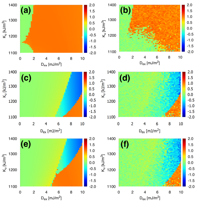
This procedure allowed us to construct phase diagrams mapping skyrmion number to combinations of and in the absence of magnetic field and electric currents, with K. Regions with correspond to uniform states or states with a single domain wall. Regions with correspond to a single stable skyrmion in the disk. Regions with correspond to more complex multidomain phases which will not be discussed. Diagrams for disks with different diameters (, and nm diameter or side) and initial states (VL, HG or saturated) are shown in Fig. 1.
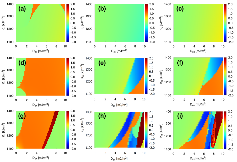
The diagrams show that nm diameter disks only present a stable skyrmion ground state at 0 K for a few combinations of anisotropy constant and DMI, if the initial state is VL (the orange regions in Fig. 1, diagram (a)). In the other scenarios tested (HG and uniform initial states), a skyrmion cannot be stabilized in the ground state within the ranges of anisotropy constant and DMI investigated. The phase diagrams of and nm disks show that a more complex picture emerges when the disk size is increased. Broad regions with (Fig. 1(d) – (i), orange) indicate that a stable skyrmion ground state could be reached for many combinations of and in these disks. The 64 nm diagrams display large regions where a stable skyrmion ground state was reached, with the region size strongly dependent on the initial state of the disk in the simulation (Fig. 1(d) – (f), orange). Disks initially in a VL state reached a stable skyrmion ground state for most combinations of and studied, while for a HG initial state, the stability region is smaller and confined to a low and high part of the diagram. Uniform initial states yielded a larger stability region, again for low and high .
In nm disks (Fig. 1 (g), (h) and (i)), more complex diagrams were obtained, with stable skyrmion ground states occurring for several combinations of and (orange regions) and for all initial conditions. In these diagrams, regions with are present, being related to more complex multidomain structures stabilized when the simulation reaches equilibrium, as has already been reported by Sampaio et al.Sampaio et al. (2013) and Zhou et al.Zhang et al. (2016). Values which are not multiples of are also present in the diagrams, being related to the discrete distribution of spins in the simulations. In theory, skyrmions possess an inherent topological protection, for it is theoretically not possible to continuously change the topological charge from to , e.g., transforming a domain wall () into a skyrmionNagaosa and Tokura (2013) (). This fact is related to the well known difficulty to create skyrmions in magnetic thin films. This topological approach, however, is based on a continuous description of the magnetic crystal, while in real samples it breaks down at atomic length scales due to the discreteness of the magnetic crystal lattice, while in computational micromagnetic descriptions, the continuous approach breaks down due to the discretization of the simulated samples into finite difference cells (1 x 1 x 2 nm3 cells in the present case). This leads to the possibility of taking a spin structure from to by going through an energy barrier more linked to the micromagnetic energy balance than to topological considerations Rohart and Thiaville (2013); Rohart et al. (2016); Hagemeister et al. (2015b) which, in practice, allows intermediate values of to be found.
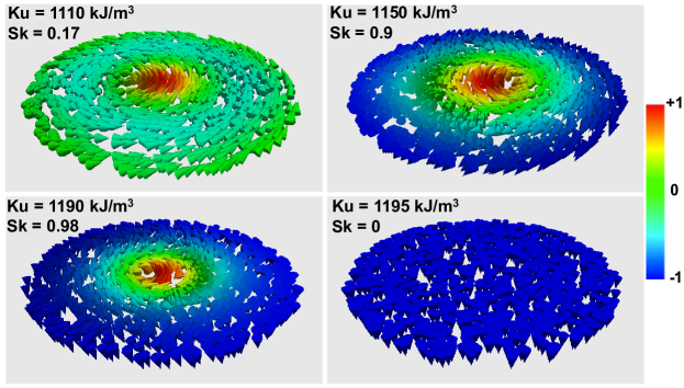
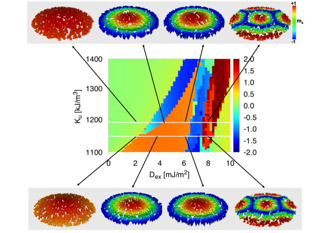
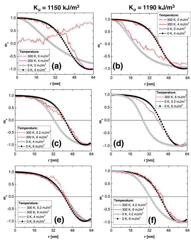
The diagrams show that, as a general rule, the presence of DMI (a finite value of ) is a necessary condition for the observation of skyrmion ground states in these disks, while the requirements on anisotropy strength seem to be less stringent. However, diagrams of 128 nm disks initially in a VL state (Fig. 1(g)) display a small region, within a narrow range of values, for which mJ/m2. This indicates that a stable skyrmion ground state can be reached in the absence of net DMI. Snapshots of a 128 nm disk along the transition to a zero-DMI skyrmion state as is increased are shown in Fig. 2. The disk goes from a ground state with to a VL skyrmion, with , as approaches kJ/m3. For higher , the disk abruptly switches to a fully saturated uniform state, in line with the diagram in Fig. 1(g). It is interesting that even though interfacial DMI, as applied in the simulations, is known to induce HG skyrmions in thin films Sampaio et al. (2013), the zero-DMI skyrmions observed are VL, typically induced by bulk DMISampaio et al. (2013); Sun et al. (2013), or magnetostatic interactionsGiovanni Finocchio and Felix Büttner and Riccardo Tomasello and Mario Carpentieri and Mathias Kläui (2016), which should be the present case. Increasing the value of causes the VL structure to evolve towards HG, as expected from this interfacial DMI in thin films (Fig. 3 shows this transition, as the DMI is increased, for two values of ). This transition is also observed in nm squares (data not shown), and suggests that zero-DMI skyrmions appear as a result of the interplay between magnetostatic, exchange and anisotropy energies in these systems. It will be shown that this state is significantly less robust than skyrmions arising when the system has finite DMI, being more easily destroyed by magnetic fields or electric currents. Interestingly, this state persists at room temperature (Figs. 6 and 7(b)). Zero-DMI skyrmions have been previously reported in the literatureGarcia, F. and Westfahl, H. and Schoenmaker, J. and Carvalho, E. J. and Santos, A. D. and Pojar, M. and Seabra, A. C. and Belkhou, R. and Bendounan, A. and Novais, E. R. P. and Guimarães, A. P. (2010); Sun et al. (2013); Dai et al. (2013); Xie and Sang (2014). In ref. Xie and Sang (2014), the skyrmion ground state resulted from a complex interplay of anisotropy, exchange and magnetostatic interactions specific to the Co/Ru/Co multilayers studied, while in Garcia, F. and Westfahl, H. and Schoenmaker, J. and Carvalho, E. J. and Santos, A. D. and Pojar, M. and Seabra, A. C. and Belkhou, R. and Bendounan, A. and Novais, E. R. P. and Guimarães, A. P. (2010), the authors were able to observe, using photoelectron emission microscopy (PEEM), a HG skyrmion in a Co/Pt disk at room temperature within a narrow range of anisotropy values. InSun et al. (2013); Dai et al. (2013), magnetostatic coupling to overlying nanostructures is exploited to stabilized the skyrmion.
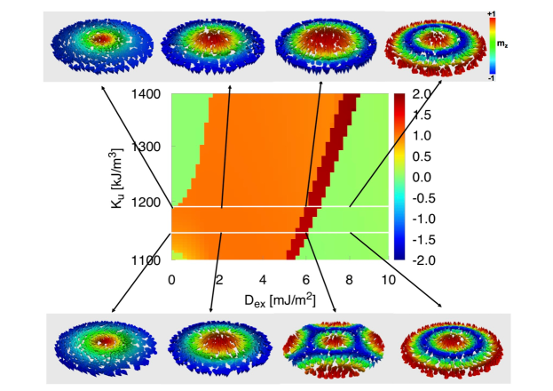
The simulations starting with the disk in a uniform state (Fig. 1, (c), (f) and (i)) yield phase diagrams resembling the phase diagrams (e) and (h) (HG initial state). In the absence of DMI, all the disks initially uniform stay uniform due to the strong uniaxial out-of-plane anisotropy present. But as is increased, a more complex diagram emerges, with stable skyrmions, multidomain and uniform states appearing for certain combinations of and . The similarity to HG diagrams can be understood from a more careful analysis of the time evolution of the disk magnetization from a initial HG skyrmion at s. Once the simulation starts, this skyrmion quickly collapses, leaving the disk in a uniform state which evolves towards the final equilibrium states in the diagram. This shows that the time evolution of the simulations with HG or uniform initial states are practically the same and lead to very similar diagrams of Figs. 1(e) and (f) or (h) and (i). The slight differences are ascribed to the different pathways in parameter space followed by the system until it reaches its ground state (and to a few cases in which the initial skyrmion might not have collapsed). In particular, the transition from the uniform to the skyrmion state involves overcoming the energy barrier associated with changing from to . Snapshots of the magnetic structures of nm disks initially uniform, corresponding to several combinations of and , show that the skyrmions appearing for are always HG (Figure 4), as reported in the literature. If the initial state is VL, the skyrmion generally does not collapse into a uniform state, but evolves towards HG, favored by the interfacial DMI term () of the simulations.
III.2 Skyrmion stability with finite temperature
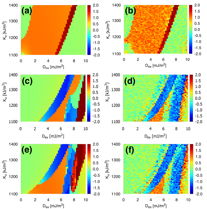
A finite temperature of K was introduced in the simulations in order to study the robustness of the skyrmion ground states at room temperature. Thus, the phase diagrams obtained are more fit for comparison with experimental results. The K phase diagrams of and nm disks are shown in Figs. 5 and 6 along with the respective K diagrams for comparison (diagrams of nm disks are not shown because no skyrmion ground state was observed at K in these disks). The finite temperature has two effects on the skyrmion ground states: (i) regions where skyrmions are stable at K are smaller at K, sometimes even disappearing completely; (ii) fuzzier borders now separate different regions in the diagrams, suggesting that the phases (skyrmionic, uniform or multidomain) are no longer well defined for the combinations of and along these borders. As an example, the stability range of a nm disk with a uniform initial state and kJ/m3 goes from mJ/m2 at K to mJ/m2 at K, a general effect observed for all combinations of and investigated. Thermally-induced random switching between skyrmionic and uniform phases has been observed in Monte Carlo simulations of hexagonal ferromagnetic structures mimicking Pd/Fe/Ir(111) samples at temperatures close to a critical valueHagemeister et al. (2015b). The switching between phases occurred when the thermal energy was comparable to the micromagnetic energy barrier separating the skyrmion from the uniform phase. In that work, the value of was kept constant while the external magnetic field and temperature were varied. Nonetheless, the random switching between phases induced by finite temperature is in line with our observation of less well defined phase boundaries separating the skyrmionic phase from uniform or multidomain states. The overall prevalence of the skyrmionic phase observed in our results is also in line with these resultsHagemeister et al. (2015b), which revealed a much smaller attempt frequency for skyrmion annihilation than for skyrmion creation, when the thermal dependence of the skyrmion lifetimes are analyzed by means of an Arrhenius law. This supports our finding that, despite the smaller areas in the K phase diagrams, they do not disappear completely, showing a good potential for skyrmion stability at room temperatures for these combinations of and . It is important to highlight that in Hagemeister et al. (2015b) the authors conclude by proposing the use of multilayers in order to increase the exchange coupling () and the DMI. Increasing these parameters would make stable room temperature skyrmions viable, according to their findings, and in this work we are exploring skyrmion stability for material parameter values typically found in Co thin film-based systems.
III.3 Skyrmion sizes
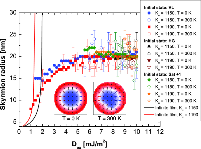
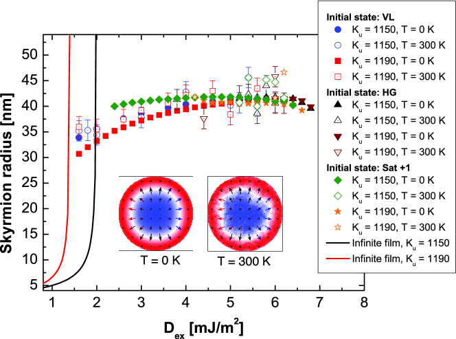
The average skyrmion core radius was determined from skyrmion profiles in order to analyze the evolution of skyrmion size with at both temperatures for and disks. The profiles are plots of reduced magnetization along the disk radius (Figs. 7) for disks with and kJ/m3. The radius is defined as the distance from the disk center to the line. If K, several profiles along different radial cuts are used to determine the average radius. The evolution of the core radius within the corresponding stability regions is plotted against for several initial states and both temperatures in Figs. 8 (64 nm) and 9 (128 nm). The lines show the expected behavior for an infinite film, where an analytical solution of the micromagnetic problem is possible, and yields the following expression for the skyrmion core radius Rohart and Thiaville (2013):
| (2) |
where is the critical DMI energy constant above which domain walls will appear in an infinite film Rohart and Thiaville (2013) and is the theoretical domain wall width parameter.
The results show that the core radius tends to fall around the same average value, corresponding to of the disk radius, regardless of disk size, a result of the confinement effect imposed by the disk finite diameter Rohart and Thiaville (2013); Sampaio et al. (2013). Furthermore, the radius evolution with is the same for all initial conditions and temperatures, indicating the dominance of the DMI in the formation and stability of these spin structures. Notably, within the stability ranges, temperature does not alter significantly the radius of skyrmions in the disks. As expected, the skyrmion radius increases with DMI strength Rohart and Thiaville (2013), but in this case it saturates due to the confinement effect. Figs. 8 and 9 also show the edge effect on the skyrmion radius as a slight decrease in the skyrmion core radius before its disappearance for high DMI values. Due to confinement inside the disk, the skyrmion radius is limited by the edges and decreases slightly before the skyrmion transitions to more complex non-collinear structures favored by the higher DMI Beg et al. (2015); Rohart and Thiaville (2013); Sampaio et al. (2013). Finally, the finite temperature partially suppresses, but does not eliminate, the zero-DMI skyrmion ground states of 128 nm disks (Figs. 6(b) and 7(b)).
III.4 Skyrmion stability under applied magnetic fields
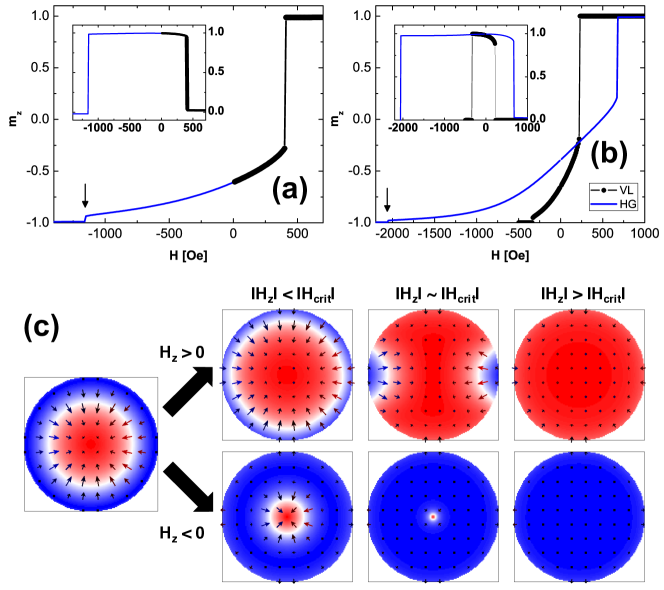
The stability of the skyrmion ground states achieved in 64 and 128 nm disks was tested against out-of-plane magnetic fields by applying positive and negative (parallel/antiparallel to skyrmion core magnetization) magnetic field on the disks. The field magnitude is increased in 10 Oe steps from Oe to the critical value () where skyrmion annihilation is observed. These tests were done both at K and K. At K, a conjugate gradient energy minimization routine is used at each field step, but for K this routine is not available in mumax3, so each field step must be applied during a fixed time ( ns).
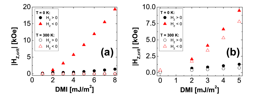
For fields parallel to the skyrmion core (positive fields), the diameter of the skyrmion core always increases, until a critical value () where the skyrmion core touches an edge of the disk and forms a highly unstable domain wall that quickly disappears (Fig. 10). Interestingly, for higher values of DMI, the skyrmion would in some cases evolve towards a 360∘ domain wall (effectively a pair of 180∘ Néel walls with same chirality). The disk would then remain in this highly stable configuration at a fixed value of field, only reaching the uniform state for much larger fields. When negative fields are applied, the skyrmion core shrinks continuously until its complete disappearance at , as shown in Fig. 10. Noticeably, the magnitude of the negative critical fields for skyrmion annihilation are substantially larger in a few cases: , which is explained by the magnetostatic repulsion of the edges of the skyrmion core as it shrinks. It is important to stress that no modifications in skyrmion structure (VL or HG) have been observed under applied magnetic field, and that no skyrmion motion has been observed during the process. The absolute value of the annihilation field is always larger for HG skyrmions, with mJ/m2, indicating that the energy barrier for skyrmion annihilation is larger in this case, in line with results in the literature showing HG as the stable skyrmion topology predominantly found in magnetic ultrathin films Giovanni Finocchio and Felix Büttner and Riccardo Tomasello and Mario Carpentieri and Mathias Kläui (2016); Sampaio et al. (2013). While VL skyrmions can appear with mJ/m2 within narrow ranges, they are much less stable than HG skyrmions, being easily destroyed by out-of-plane fields as low as Oe, while the lowest annihilation field of an HG skyrmion is Oe.
At room temperature ( K), the same overall behavior is observed: positive fields lead to skyrmion annihilation after its core reaches the disk edge and negative fields shrink the core until it disappears, the former process occurring at lower field magnitudes than the latter. When compared to 0 K, all the critical field magnitudes at K are lower. The critical fields are shown in Table 1, and their dependence with DMI in shown in Fig. 11. For both disk sizes, the annihilation fields are lower at 300 K, but this reduction is drastic (two orders of magnitude) for 64 nm disks, evidencing a much lower energy barrier separating the skyrmion state from the uniform state at this size. Another interesting fact observed in 64 nm disks is that the asymmetry between positive and negative critical fields vanishes at K .
| 64 nm | 128 nm | |||
|---|---|---|---|---|
| (mJ/m2) | ||||
III.5 Skyrmion stability under spin polarized currents
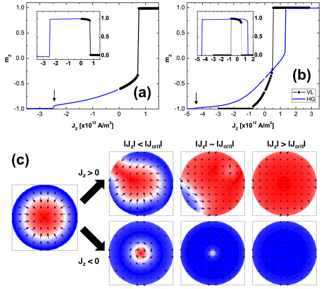
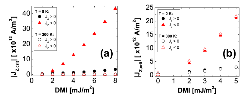
The effect of spin polarized electric currents, by means of Slonczewski-like STT, on the same structures tested in Secs. III.2, III.3 and III.4 was investigated at and K for the same values of and . Currents were applied along the z axis (perpendicular to the disk plane) with out-of-plane spin polarization of Sampaio et al. (2013) and non-adiabaticity . At both temperatures, the initial value of the current density was always equal to x A/m2 ( TA/m2, equivalent to and A for 64 and 128 nm disks, respectively) and its magnitude was increased in TA/m2 steps until the critical current density for skyrmion annihilation, , was reached (Fig. 12). For 64 nm skyrmions at 300 K, the applied currents had to be drastically reduced (several orders of magnitude) due to the extreme instability of the skyrmions under electric current in these samples at room temperature.
For both disk diameters it was observed that, for low DMI, HG skyrmions always tend to a VL structure, regardless of the current sense (Figs. 12; similar transformations of skyrmion structure under applied currents have been previously reported Liu et al. (2015); Zhang et al. (2016)). At K, positive currents (negative electron flow) cause the skyrmion core diameter to increase until annihilation, which occurs after the core touches the disk edge, forming an unstable domain wall, in analogy to the field-driven annihilation process previously observed. For negative currents, the skyrmion core diameter shrinks until its disappearance, which happens at critical currents with magnitudes much larger than the positive critical currents (again, in analogy to what was observed with applied magnetic fields). At K, similar dynamics is observed, but the critical current magnitudes are always lower. Again, in the 64 nm disks, the reduction in critical current values is drastic at K, with critical currents 12 orders of magnitude below those observed in 128 nm disks under the same conditions. This amounts to very unstable skyrmions under current in these disks, especially if such current values are comparable to the noise level of the integrated electronic circuits where these disks are meant to operate. This shows that the size of the nanostructure supporting the skyrmion may have an enormous impact in its stability, with very small structures with and DMI values within the investigated ranges not feasible at room temperature. Finally, it is interesting to note that the skyrmion shrinking or expansion process under current (or magnetic field) is reversible, with the skyrmion returning to its original diameter once the current (or field) is removed. On the other hand, the skyrmion annihilation process is always irreversible, which means that if the current (or field) is removed after annihilation, the disk remains in a uniform state.
| 64 nm | 128 nm | |||
| (mJ/m2) | / | / | / | / |
.
IV Conclusion
Micromagnetic simulations of magnetic nanosize disks achieving their ground state from several initial configurations indicate that a single, confined skyrmion can be stable in these structures only for a few combinations of uniaxial anisotropy constant and Dzyaloshinskii-Moriya interaction, under ideal conditions ( K and defect-free sample). The results also show that this skyrmion ground state depends on the initial condition of the simulated disks. At room temperature, fewer of these combinations are available, as evidenced by the smaller regions in the phase diagrams. This indicates that the fabrication of nanostructures capable of sustaining a stable skyrmion ground state relies critically on the fine tuning of these magnetic parameters especially for devices working at room temperature. 32 nm disks could only sustain a stable skyrmion a few cases, always at K, while 64 and 128 nm disks had more combinations of and for which a skyrmion ground state was stable, both at 0 K and 300 K. These ground states were always stable in the absence of magnetic fields, a fundamental condition for non-volatile data storage applications.
The results indicate that high values of uniaxial anisotropy and high values of DMI do not favor a skyrmion ground state in these magnetic disks. A high value of uniaxial anisotropy constant will not favor the smooth transition from to from the skyrmion center to its periphery, while a high value of DMI favors spin rotation leading to spirals or multidomain states. On the other hand, a small DMI is necessary to stabilize a single skyrmion in a disk, and in the absence of DMI a very fragile vortex-like skyrmion ground state is achieved only within a narrow range of , for 128 nm, defect-free disks at both temperatures investigated. This skyrmion ground state is easily destroyed by magnetic fields or electric currents, but, surprisingly, it is robust against thermal agitation. The initial condition of the simulations is fundamental for the observation of these zero-DMI skyrmions, for even though pre-existent skyrmions can be stabilized even in the absence of DMI, the transition from a uniform magnetic state to a skyrmion is only observed in cases where a sizeable DMI is present. Furthermore, while all zero-DMI skyrmions observed were vortex-like, with the introduction of DMI causing them to become HG, a configuration favored by the interface-induced DMI employed in the simulations.
The skyrmion ground states observed can be quite stable under out-of-plane magnetic fields or spin-polarized currents. For positive fields/currents, the edge of the disk plays a major role in skyrmion annihilation, since the increase is its diameter eventually causes its border to touch the disk edge, leading to annihilation. For negative fields/currents, the critical fields/currents for skyrmion annihilation are much larger, because in this case their sense is antiparallel to the skyrmion core magnetization, effectively squeezing it and increasing the magnetostatic repulsion between the skyrmion walls. Finite temperatures introduce thermal agitation that tends to narrow stability regions in the phase diagrams, and to decrease the absolute values of the critical annihilation fields/currents. This is critical in the 64 nm disks, where it was observed that the skyrmions are easily destroyed by very small field/currents at room temperature. So, despite the larger skyrmion stability regions observed in their phase diagrams, 64 nm disks are less interesting for room temperature devices relying on magnetic fields or electrical currents for their operation. It is important to stress that in all these simulations defects in the samples were not considered. Structural defects commonly found in magnetic thin film-based nanostructures can introduce fluctuations in or , which lead to pinning and complex magnetization dynamics such as domain wall creepLemerle et al. (1998); Metaxas et al. (2007); Chauve et al. (2000). Defects are known to pin skyrmions in nanostructuresBoulle et al. (2016), but the effects of fluctuations in anisotropy or DMI on their formation and stability is still, to our knowledge, unknown, and could play a major role in their statics and dynamics. These results show that the conditions for skyrmion stability in a single magnetic disk demand a high degree of refinement in multilayer engineering and magnetic nanostructure fabrication, especially for room temperature applications, where achieving the right combination of , DMI and diameter is paramount.
Acknowledgements.
The authors are grateful to Dr. Alberto R. Torres for granting access to the computational facilities of the UFSC Physics Department. The authors acknowledge financial support from Brazilian agencies CNPq, CAPES and FAPERJ.References
References
- Krause and Wiesendanger (2016) S. Krause and R. Wiesendanger, Nat Mater 15, 493 (2016).
- nat (2013) “Skyrmionics in sight,” Editorial in Nature Nanotechnology, 8, 883 (2013).
- Nagaosa and Tokura (2013) N. Nagaosa and Y. Tokura, Nature Nanotechnology 8, 899 (2013).
- Fert et al. (2013) A. Fert, V. Cros, and J. Sampaio, Nature Nanotechnology 8, 152 (2013).
- Woo et al. (2016) S. Woo, K. Litzius, B. Krüger, M.-Y. Im, L. Caretta, K. Richter, M. Mann, A. Krone, R. Reeve, M. Weigand, A. P., I. Lemesh, M.-A. Mawass, P. Fischer, M. Kläui, and G. S. D. Beach, Nat. Mater. 15, 501 (2016).
- Hagemeister et al. (2015a) J. Hagemeister, N. Romming, K. von Bergmann, E. Y. Vedmedenko, and R. Wiesendanger, Nature Communications 6, 8455 (2015a).
- Beg et al. (2015) M. Beg, R. Carey, W. Wang, D. Cortés-Ortuño, M. Vousden, M.-A. Bisotti, M. Albert, D. Chernyshenko, O. Hovorka, R. L. Stamps, and H. Fangohr, Scientific Reports 5, 17137 (2015).
- Rossler et al. (2006) U. K. Rossler, A. N. Bogdanov, and C. Pfleiderer, Nature 442, 797 (2006).
- Mühlbauer, S. and Binz, B. and Jonietz, F. and Pfleiderer, C. and Rosch, A. and Neubauer, A. and Georgii, R. and Böni, P. (2009) Mühlbauer, S. and Binz, B. and Jonietz, F. and Pfleiderer, C. and Rosch, A. and Neubauer, A. and Georgii, R. and Böni, P., Science 323, 915 (2009).
- Heinze, S. and von Bergmann, K. and Menzel, M. and Brede, J. and Kubetzka, A. and Wiesendanger, R. and Bihlmayer, G. and Blügel, S. (2011) Heinze, S. and von Bergmann, K. and Menzel, M. and Brede, J. and Kubetzka, A. and Wiesendanger, R. and Bihlmayer, G. and Blügel, S., Nature Physics 7, 713 (2011).
- Tretiakov and Tchernyshyov (2007) O. A. Tretiakov and O. Tchernyshyov, Phys. Rev. B 75, 012408 (2007).
- Iwasaki et al. (2013) J. Iwasaki, M. Mochizuki, and N. Nagaosa, Nature Nanotechnology 8, 742 (2013).
- Sampaio et al. (2013) J. Sampaio, V. Cros, S. Rohart, A. Thiaville, and A. Fert, Nature Nanotechnology 8, 839 (2013).
- Koshibae and Nagaosa (2014) W. Koshibae and N. Nagaosa, Nature Communications 5, 5148 (2014).
- Sun et al. (2013) L. Sun, R. X. Cao, B. F. Miao, Z. Feng, B. You, D. Wu, W. Zhang, A. Hu, and H. F. Ding, Phys. Rev. Lett. 110, 167201 (2013).
- Loreto et al. (2017) R. Loreto, W. Moura-Melo, A. Pereira, X. Zhang, Y. Zhou, M. Ezawa, and C. de Araujo, Journal of Magnetism and Magnetic Materials (2017).
- Novais et al. (2011) E. R. P. Novais, P. Landeros, A. G. S. Barbosa, M. D. Martins, F. Garcia, and A. P. Guimarães, J. Appl. Phys. 110, 053917 (2011).
- Zhou and Ezawa (2014) Y. Zhou and M. Ezawa, Nature Communications 5, 4652 (2014).
- Romming et al. (2013) N. Romming, C. Hanneken, M. Menzel, J. E. Bickel, B. Wolter, K. von Bergmann, A. Kubetzka, and R. Wiesendanger, Science 341, 636 (2013).
- Boulle et al. (2016) O. Boulle, J. Vogel, H. Yang, S. Pizzini, D. de Souza Chaves, A. Locatelli, T. O. Menteş, A. Sala, L. D. Buda-Prejbeanu, O. Klein, M. Belmeguenai, Y. Roussigné, A. Stashkevich, S. M. Chérif, L. Aballe, M. Foerster, M. Chshiev, S. Auffret, I. M. Miron, and G. Gaudin, Nat. Nano. 11, 449 (2016).
- Moreau-Luchaire et al. (2016) C. Moreau-Luchaire, C. Moutafis, N. Reyren, J. Sampaio, C. A. F. Vaz, N. Van Horne, K. Bouzehouane, K. Garcia, C. Deranlot, P. Warnicke, P. Wohlhüter, J. George, M. Weigand, J. Raabe, V. Cros, and A. Fert, Nat. Nano. 11, 444 (2016).
- Jiang et al. (2015) J. Jiang, P. Upadhyaya, W. Zhang, G. Yu, M. B. Jungfleisch, F. Y. Fradin, J. E. Pearson, Y. Tserkovnyak, K. L. Wang, O. Heinonen, S. G. E. te Velthuis, and A. Hoffmann, Science 349, 283 (2015).
- Note (1) We stick to the nomenclature used by Sampaio et al. in Sampaio et al. (2013). In other works, an alternative nomenclature is used, where a vortex-like skyrmion is called a Bloch skyrmion, and a hedgehog skyrmion becomes a Néel skyrmion.
- Vansteenkiste et al. (2014) A. Vansteenkiste, J. Leliaert, M. Dvornik, M. Helsen, F. Garcia-Sanchez, and B. Van Waeyenberge, AIP Advances 4, 107133 (2014).
- Brown (1963a) W. F. Brown, Journal of Applied Physics 34, 1319 (1963a).
- Brown (1963b) W. F. Brown, Phys. Rev. 130, 1677 (1963b).
- Rohart et al. (2016) S. Rohart, J. Miltat, and A. Thiaville, Phys. Rev. B 93, 214412 (2016).
- Zhang et al. (2016) X. Zhang, Y. Zhou, and M. Ezawa, Phys. Rev. B 93, 024415 (2016).
- Rohart and Thiaville (2013) S. Rohart and A. Thiaville, Phys. Rev. B 88, 184422 (2013).
- Hagemeister et al. (2015b) J. Hagemeister, N. Romming, K. von Bergmann, E. Y. Vedmenko, and R. Wiesendager, Nat. Comm. 6, 8455 (2015b).
- Giovanni Finocchio and Felix Büttner and Riccardo Tomasello and Mario Carpentieri and Mathias Kläui (2016) Giovanni Finocchio and Felix Büttner and Riccardo Tomasello and Mario Carpentieri and Mathias Kläui, Journal of Physics D: Applied Physics 49, 423001 (2016).
- Garcia, F. and Westfahl, H. and Schoenmaker, J. and Carvalho, E. J. and Santos, A. D. and Pojar, M. and Seabra, A. C. and Belkhou, R. and Bendounan, A. and Novais, E. R. P. and Guimarães, A. P. (2010) Garcia, F. and Westfahl, H. and Schoenmaker, J. and Carvalho, E. J. and Santos, A. D. and Pojar, M. and Seabra, A. C. and Belkhou, R. and Bendounan, A. and Novais, E. R. P. and Guimarães, A. P., Appl. Phys. Lett. 97, 022501 (2010).
- Dai et al. (2013) Y. Y. Dai, H. Wang, P. Tao, T. Yang, W. J. Ren, and Z. D. Zhang, Phys. Rev. B 88, 054403 (2013).
- Xie and Sang (2014) K. Xie and H. Sang, Journal of Applied Physics 116, 223901 (2014).
- Liu et al. (2015) R. H. Liu, W. L. Lim, and S. Urazhdin, Phys. Rev. Lett. 114, 137201 (2015).
- Lemerle et al. (1998) S. Lemerle, J. Ferré, C. Chappert, V. Mathet, T. Giamarchi, and P. Le Doussal, Phys. Rev. Lett. 80, 849 (1998).
- Metaxas et al. (2007) P. J. Metaxas, J.-P. Jamet, A. Mougin, M. Cormier, J. Ferré, V. Baltz, B. Rodmacq, B. Dieny, and R. L. Stamps, Phys. Rev. Lett. 99, 217208 (2007).
- Chauve et al. (2000) P. Chauve, T. Giamarchi, and P. Le Doussal, Phys. Rev. B 62, 6241 (2000).