-symmetric gain and loss in a rotating Bose-Einstein condensate
Abstract
-symmetric quantum mechanics allows finding stationary states in mean-field systems with balanced gain and loss of particles. In this work we apply this method to rotating Bose-Einstein condensates with contact interaction which are known to support ground states with vortices. Due to the particle exchange with the environment transport phenomena through ultracold gases with vortices can be studied. We find that even strongly interacting rotating systems support stable -symmetric ground states, sustaining a current parallel and perpendicular to the vortex cores. The vortices move through the non-uniform particle density and leave or enter the condensate through its borders creating the required net current.
I Introduction
One of the most desired effects studied in Bose-Einstein condensates is the formation of vortices that arise when the condensates are brought into rotation Fetter (2009). Vortices were first studied in different low-temperature quantum systems such as superfluid helium Feynman (1955) and superconductors Abrikosov (1957). In 1961, the Gross-Pitaevskii equation was formulated to describe vortices in a Bose-Einstein condensate Pitaevskii (1961); Gross (1961). Shortly after the first realizations of these ultracold condensates Davis et al. (1995); Anderson et al. (1995), Butts and Rokhsar Butts and Rokhsar (1999) used a variational approach consisting of a linear combination of the low-energy angular-momentum eigenstates of the harmonic oscillator to show that such vortices form themselves if the Bose-Einstein condensate is rotated. Only months later the calculations where experimentally confirmed by Madison et al. Madison et al. (2000). At this time, numerical methods such as the finite-element method made the exact numerical study of these systems possible, thus providing a much higher precision Bao (2007).
The study of transport phenomena is a common interest in Bose-Einstein condensates, e.g., through optical lattices Choi and Niu (1999) or even random potentials Clément et al. (2005), as well as in superfluids Putterman (1974); Pethick et al. (1977), and, naturally, in superconductors Campbell and Evetts (1972). If a Bose-Einstein condensate is discussed in the mean-field approximation of the Gross-Pitaevskii equation, the necessary particle gain and loss can be described by imaginary potentials Kagan et al. (1998), rendering the Hamiltonian non-Hermitian Moiseyev (2011). Up to now, such Hamiltonians have been studied extensively Kagan et al. (1998); Schlagheck and Paul (2006); Rapedius and Korsch (2009); Rapedius et al. (2010); Abdullaev et al. (2010); Bludov and Konotop (2010); Witthaut et al. (2011) and the particle in- and out-coupling were compared to many-particle calculations justifying their use in mean-field theory Rapedius (2013); Dast et al. (2014). The particle loss can be induced by a focused electron beam Gericke et al. (2008) while particles are added by letting them fall into the condensate from a second condensate Robins et al. (2008).
In 1998, Bender and Boettcher Bender and Boettcher (1998) discovered that non-Hermitian Hamiltonians can support stationary solutions if they are symmetric. This finding not only opened the possibility of postulating new theoretical concepts to replace the long accepted requirement of Hermitian Hamiltonians Bender et al. (2002); Mostafazadeh (2008, 2010) but started many other theoretical and experimental studies in optical El-Ganainy et al. (2007); Klaiman et al. (2008); Musslimani et al. (2008); Makris et al. (2008, 2010); Guo et al. (2009); Rüter et al. (2010); Peng et al. (2014); Regensburger et al. (2012) and electronic systems Schindler et al. (2011); Bender et al. (2013). In these systems, the non-Hermitian Hamiltonian does not describe the full quantum mechanical system but a macroscopic quantity such as the electric field in a wave guide system or the electric current. Inspired by the proposal of Klaiman et al. Klaiman et al. (2008), Bose-Einstein condensates were studied as an additional realization using a double-well system, where particles are injected into one well and removed from the other Cartarius et al. (2012); Cartarius and Wunner (2012); Dast et al. (2013a, b); Haag et al. (2014).
These studies show that -symmetric condensates provide an excellent framework for the theoretical study of particle transport through vortex systems. There exists a vast amount of numerical and exact analytical calculations, describing stationary vortex states in -symmetric systems Achilleos, V. and Kevrekidis, P. G. and Frantzeskakis, D. J. and Carretero-González, R. (2012); Konotop et al. (2016); Schwarz, Lukas and Cartarius, Holger and Musslimani, Ziad H. and Main, Jörg and Wunner, Günter (2017). However, these vortex states are not stable ground states but instead highly excited states. Due to the -symmetric potential, the vortex structure of such states is typically lost for strong particle in- and out-coupling.
The formation of vortices in the ground state can be achieved by rotating a non-isotropic trap Landau and Pitaevskii (1979), stirring the condensate Madison et al. (2000), or inducing a synthetic magnetic field Lin et al. (2009); Zhao and Gu (2015). The different methods all lead to similar equations of motion Landau and Pitaevskii (1979); Madison et al. (2000); Zhao and Gu (2015), one of which is the Gross-Pitaevskii equation in a rotating frame. In natural units and for a rotation axis and angular frequency it reads
| (1) | ||||
where describes the rotating potential in the rotating frame.
A solution is stationary with respect to the rotating frame and fulfills the stationary rotating Gross-Pitaevskii equation,
| (2) | ||||
Note that for the wave functions in the rotating and laboratory frame are the same. It can be directly seen that the mean-field energy in the rotating frame differs from the non-rotating form, , and reads
| (3) |
If the potential lacks complete rotational symmetry, a non-rotating state can no longer be stationary. The ground state of the system is then determined by the modified mean-field energy Landau and Pitaevskii (1979), allowing the study of vortex filaments in superfluids and other coherent quantum material.
Before discussing our numerical results, we have to emphasize that since the potential is time independent in the rotating frame it rotates with the same frequency as the condensate. In particular in the case of potentials that are not isotropic in the rotating plane, this must be considered. We use an ansatz of two- and three-dimensional B-splines for the algorithm described in Haag et al. (2015). To achieve more accurate results, the density of elements in the coordinate space are chosen recursively such that the error of the kinetic part is minimized. In Sec. II a two-dimensional study of a rotating -symmetric potential is studied. To study particle transport along the vortices, a three-dimensional study is performed in Sec. III, followed by a short conclusions in Sec. IV.
II Two-dimensional system
Due to the enormous numerical advantage it is reasonable to start with two-dimensional calculations, i.e., the lowest dimensional system that can provide states with vortices. To illustrate the reduction from three to two dimensions consider a harmonic oscillator with the radial trapping frequency and the axial trapping frequency ,
| (4) |
For a linear system a separation into the radial and the axial parts is possible. Due to strong axial trapping frequencies excitations in this direction are suppressed and the wave function assumes the shape of the harmonic oscillator ground state in that direction.
The interaction energy in the remaining two-dimensional equation, , equals the interaction energy in the original three-dimensional system if one assumes for the trapping in -direction. In this case, the rotating Gross-Pitaevskii equation in two dimensions assumes the form
| (5) | ||||
where the interaction strength appears unmodified. For stronger repulsive contact interactions this approximation is not exact and an even tighter trapping in -direction must be employed. However, in this section, an adequately strong trapping frequency is assumed and the interaction strengths are fixed.
To describe the in- and out-coupling of particles the -symmetric imaginary potential
| (6) |
is used. For positive values of the potential describes a gain of particles for and a loss of particles for . The potential is constant in both regions. This ensures that the same amount of particles is coupled in and out of the system for every possible -symmetric wave function. Thus, a comparison between different parameter sets and different numbers of vortices is directly possible. It must be emphasized that the potential is used inside the rotating frame and therefore is itself rotating around the point , i.e., the gain and loss contributions are rotating alongside the wave function.
The starting point of this discussion is the case of an isolated system. For the two-dimensional analysis performed in this section the strength of the nonlinearity is fixed to . To reveal the multiple vortex ground states predicted by Butts et al. Butts and Rokhsar (1999) various vortex configurations were created to act as initial values for the nonlinear root search used in the finite-element method. Using imaginary time propagation and careful tracing of all branches of solution found, we identified a total of six different ground states in the range of the rotation frequency from to . Four of these states are shown in Fig. 1, possessing one ( in (a)), two ( in (b),(c)), three ( in (d)), or four ( in (e),(f)) vortices.
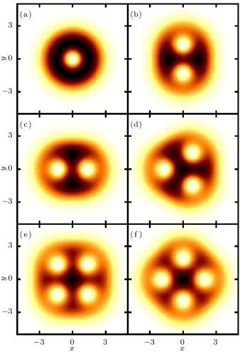
These states, with the exception of the state with one central vortex, , do not have rotational symmetry but instead show a two-, three- and four-fold symmetry, respectively. For the sake of completeness we note that in the parameter regime discussed in this section, an additional ground state with four vortices but twofold symmetry can be observed for . Applying higher rotation frequencies, the number of vortices would increase even further, until hexagonal vortex grids can be observed Fetter (2009).
By switching on the -symmetric potential (6), the stationary states , , and become subject to a gain and loss of particles. The imaginary part of the potential, and therefore the particle exchange rotates concurrently with the wave function. The -symmetric potential at induces a current in -direction. Real eigenvalues and stable behavior can therefore only be expected if the particle density at is symmetric with respect to the reflection . Figure 1 shows all possible orientations of the four states that fulfill this requirement.
The stability of all states is analyzed via the Bogoliubov-de Gennes equations in the rotating frame,
| (7a) | |||
| (7b) | |||
The mean-field energy of the four ground states is shown together with their dynamical stability in Fig. 2.
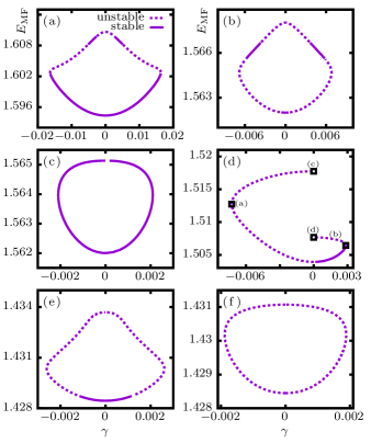
The most prominent feature of these spectra is that most of them are even functions of . This is a consequence of their symmetry which can be seen as follows. A reflection of both coordinates and obviously leaves the Gross-Pitaevskii equation (5) invariant if the wave function itself is invariant under this operation. However, the reflection in -direction inverts the imaginary potential (6) and can be absorbed in the transformation . Therefore, every state that is symmetric in -direction for , must therefore have an eigenvalue spectrum that is symmetric with respect to .
All ground states exist up or down to some critical value where they coalesce with excited states and vanish (inverse tangent bifurcation). This is the typical behavior known from -symmetric systems. However, due to the vortices, it is not a priori clear what drives the necessary current, i.e., how the necessary phase gradient is generated. To understand the principles of this mechanism the case is studied in more detail. Figure 2(d) clearly shows that there are two bifurcation partners and two tangent bifurcations. The two states at the bifurcations and the bifurcation partners for , as marked in Fig 2(d) are shown in Fig. 3.
For each state not only the square modulus of the wave function is analyzed but the particle current density in the non-rotating frame is studied in detail to understand how the currents around the vortices contribute to the net current enforced by the particle gain and loss.
For negative values of the net current in the wave function (a) must run downwards. This behavior is produced by shifting all three vortex centers to the right while keeping the overall particle density mostly intact. This results in a situation where the current in downward direction on the left side of the wave function is strongly enhanced due to the stronger density. The exact opposite behavior can be found in the case of positive values of , where all vortices shift to the left increasing the net current upwards (b).
This is, however, not the only mechanism that changes the net current of these vortex states. A second mechanism can be seen when analyzing, how the excited states shown in Fig. 3(c) and (d) behave between and the bifurcation ((a) and (b)). In complete contrast to the behavior of the ground state, not all vortices are shifted equally strong. Instead, some vortices are shifted more strongly, completely moving out of the condensate. This increases the current on this side of their neighboring vortices producing an effective current in up- or downwards direction.
For the sake of brevity, we omit a detailed discussion of the other five configurations. A in-depth study shows that these two effects capture almost every current production found in the discussed ground states. In some cases, like the central vortex state , the net current is produced by weakening the undesired current by a new vortex. In other cases, such as the configuration in Fig. 1(c) of two vortices lying on the symmetry axis, both mechanisms are found nearly canceling each other out. In this case the wave function must undergo a serious transformation even though the net currents are very weak. The bifurcation partners, analyzed at , cannot only have a different number of vortices but may also be asymmetric with respect to the reflection .
The results show some similarities to the results of Achilleos, V. and Kevrekidis, P. G. and Frantzeskakis, D. J. and Carretero-González, R. (2012), where -symmetric bifurcation partners of highly excited nonlinear vortex states are always states with one vortex more or less. However, in contrast to that work and due to the rotation contribution in our calculations, the vortex configurations are much more stable and vortices only emerge from the wave functions border and not out of a nodal plane.
III Three-dimensional system
Until now, the current always ran perpendicular to the vortex lines. This is a consequence of the restriction to two dimensions. In this section, a net current in direction of the vortices is considered. If the gain and loss of particles is homogeneous in the --plane and varies only in -direction, the imaginary part of the potential does not even need to rotate. In contrast to the two-dimensional case, the trapping in -direction is not taken to be tight but equal to the radial trapping. With this condition, , an isotropic trapping potential is obtained,
| (8) |
The imaginary potential
| (9) |
with positive values of implements a gain of particles below the --plane and a loss of particles above. The imaginary part of the potential is again constant in each of these regions to ensure that an equal amount of particles is coupled in and out of the system for any shape of the wave function, of which the particle density is at least symmetric under the transformation .
To gain access to numerical results, the finite-element method must be provided with initial values for its root search. As long as one is interested in the ground state of the system, excitations in the -direction can be excluded from this search. A good approximation to the three-dimensional wave function can therefore be found using a product state of the two-dimensional solution in - and -directions and a Gaussian ground state in -direction.
However, to reliably postulate initial values for the ground state the two- and three-dimensional systems must be comparable to start with. Since the trapping potential in -direction is much weaker than in the two-dimensional case, the modulus square of the mean-field wave function is smaller. To counterbalance this effect the particle number is increased to . The Gross-Pitaevskii equation then reads
| (10) | ||||
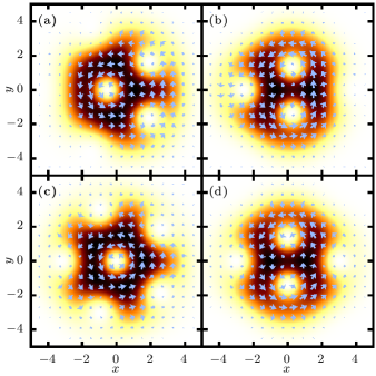
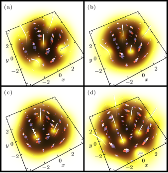
We start by presenting the rotating ground states for four different rotation frequencies in Fig. 4.
As in Sec. II all wave functions are shown in the non-rotating laboratory system at time . Therefore the figure reveals an overall circular current of particles that is consistent with the rotation of the wave function. The concrete path of a vortex core in -direction is defined by its nodal line. To permit a clear view on this path, the nodal line is highlighted by white lines. Special attention should be given to the state with three vortices in Fig. 4(c). Around the vortex lines are bent inwards towards the rotation center. This effect, even though most distinct at (c), is present in all three wave functions with vortices outside the rotation center. This can be understood since the Magnus force, which keeps the vortices on their circular track during the rotation, is stronger for regions of higher particle density, i.e., the density gradient and therefore the Magnus force Anderson et al. (2000) is increased.
By increasing the parameter , the in- and out-coupling drives a new current in the system; particles now have to be transported upwards parallel to the vortices. In case of the unrotated ground state and the four states discussed in Fig. 4 this leads to an increase of the mean-field energy, as shown in Fig. 5.
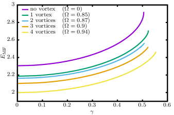
The first eye-catching result of this analysis is that all these ground states behave qualitatively the same. In fact, the bifurcation scenario resembles the behavior of the double-well system or the harmonic oscillator studied in previous investigations Cartarius and Wunner (2012); Dast et al. (2013a). All states break the symmetry shortly after in a typical tangent bifurcation. The solutions of the Bogoliubov-de Gennes equations (7) show that they are stable up to this point.
Since the rotation, controlled by the parameter , changes the wave function considerably, not only by increasing or decreasing the number of vortices but also by broadening the wave function, this similarity is quite surprising. It indicates that the --plane and the -dimension are only weakly coupled, even though the nonlinearity already provides a major contribution to the planar solutions.
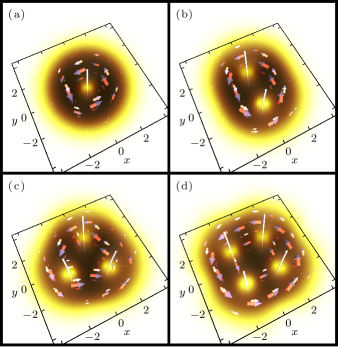
At the bifurcation point the wave functions support the strongest possible current upwards. Figure 6 shows these wave functions for the same states as in Fig. 4.
Two important effects are visible in these wave functions with maximum-current: Firstly, the number and position of the vortices in the --plane are changing. This is easy to see in Fig. 6(d). Not only have four new vortices entered the picture, the original vortices are pushed much tighter together. The new vortices have also increased the size of the wave function. This effect would be expected if either the rotation frequency is increased, or a the interaction strenghened. Due to the -symmetric current in -direction this component of the wave function cannot be chosen exactly symmetric, i.e., it does not take the shape of a Gaussian. Instead, an antisymmetric contribution is needed, considerably reducing the modulus square at . The particles are then forced to the top and bottom of the trap, increasing the particle density and the effective strength of the interaction at these areas.
Secondly, the previously discussed bending to the center of the trap is not the only deformation of the vortex lines. Following the direction of the -symmetric current upwards, the vortex lines are screwed in clockwise direction, i.e., against the direction of the frame’s rotation. To quantify this screwing, each vortex must be parametrized by the coordinate in cylindrical coordinates . The vortex screwing is then purely described by the function , which is antisymmetric with respect to the --plane; the differential defines a screwing strength.
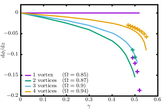
This value is shown in Fig. 7 as a function of .
The shape of all these functions are very similar. In fact, only the maximum reachable and the overall slope differ. The different maximum parameters are an obvious consequence of the different positions of the tangent bifurcations at which the ground states vanish. The different slopes are best visible for small parameters . In this regime, two qualitative dependencies are visible: Firstly, the central vortex is not bent at all. Secondly, in a stationary state with non-center vortices they are screwed times as strong as in the case of vortices.
This fact indicates that the vortex screwing supports the upward current in the system and each vortex makes an equal contribution. The strongest screwed vortices are therefore found in the two-vortex case. For stronger gain and loss new non-center vortices arise, depicted as crosses in Fig. 7. In case of the central vortex state, these new vortices are the only screwed vortices in the wave function. However, in the other two cases the additional vortices are screwed less than the original ones.
IV Conclusion
We studied a rotating Bose-Einstein condensate with a -symmetric potential describing particle in- and out-coupling. Initially, the particle transport through the ground state with multiple vortices was studied for the two-dimensional case where the net currents run perpendicular to the rotation axis, i.e., the vortex lines. Not only remain most of the states stable, at least for weak currents, but the behavior of the states producing such currents shows an interesting behavior. Either new vortices enter the condensate from the border, weakening parts of the circular currents around existing vortices, or the existing vortices move through the non-homogeneous particle distribution to modify the effective currents.
Both effects obviously arise from the finite size of the condensate, i.e., the drop of the density at its borders. Therefore, it would be worthwhile to study whether the transport phenomena described by -symmetric in- and out-coupling is indeed dominated by border currents and border effects of the condensate. The next step would be the study of a larger condensate with constant trapping potential and a bigger vortex grid.
In the next part we added the third dimension to study currents parallel to the rotation axis, i.e., in direction of the vortex lines. In the two-dimensional study weak perpendicular currents sufficed to modify the vortex structure substantially. This changes drastically in the three-dimensional case, in which even strong parallel currents do not break the -symmetry. However, the trajectory of the vortex lines in the stable ground states changes. Stronger particle in- and out-coupling strengths lead to a screwing of the vortex lines against the direction of the rotation.
There are various starting points for future studies. While an additional analysis of the stationary system could provide insight into the physical process that leads to the screwing, dynamical calculations will allow us to study how the system behaves when turning on the particle transport. Since the screwed states are stable, the ground state without particle gain and loss can be considered being a small perturbation to the screwed case, and we expect that the current excites oscillations of the vortex lines. For example, it should be possible to study the process in the framework of the dynamics of single vortices in superfluids Kevrekidis et al. (2003); Frantzeskakis et al. (2002); Anderson et al. (2000) and discuss, whether the screwing can be understood as a result of the Magnus force.
References
- Fetter (2009) A. L. Fetter, Rev. Mod. Phys. 81, 647 (2009).
- Feynman (1955) R. Feynman, Prog. Low Temp. Phys. 1, 17 (1955).
- Abrikosov (1957) A. A. Abrikosov, Sov. Phys. JETP 5, 1174 (1957).
- Pitaevskii (1961) L. P. Pitaevskii, Sov. Phys. JETP 13, 451 (1961).
- Gross (1961) E. P. Gross, Nuovo Cimento 20, 454 (1961).
- Davis et al. (1995) K. B. Davis, M.-O. Mewes, M. R. Andrews, N. J. van Druten, D. S. Durfee, D. M. Kurn, and W. Ketterle, Phys. Rev. Lett. 75, 3969 (1995).
- Anderson et al. (1995) M. H. Anderson, J. R. Ensher, M. R. Matthews, C. E. Wieman, and E. A. Cornell, Science 269, 198 (1995).
- Butts and Rokhsar (1999) D. A. Butts and D. S. Rokhsar, Nature 397, 327 (1999).
- Madison et al. (2000) K. W. Madison, F. Chevy, W. Wohlleben, and J. Dalibard, Phys. Rev. Lett. 84, 806 (2000).
- Bao (2007) W. Bao, “Ground states and dynamics of rotating Bose-Einstein condensates,” in Transport Phenomena and Kinetic Theory: Applications to Gases, Semiconductors, Photons, and Biological Systems, edited by C. Cercignani and E. Gabetta (Birkhäuser Boston, Boston, MA, 2007) pp. 215–255.
- Choi and Niu (1999) D.-I. Choi and Q. Niu, Phys. Rev. Lett. 82, 2022 (1999).
- Clément et al. (2005) D. Clément, A. F. Varón, M. Hugbart, J. A. Retter, P. Bouyer, L. Sanchez-Palencia, D. M. Gangardt, G. V. Shlyapnikov, and A. Aspect, Phys. Rev. Lett. 95, 170409 (2005).
- Putterman (1974) S. J. Putterman, Superfluid hydrodynamics (North-Holland, Amsterdam, 1974).
- Pethick et al. (1977) C. J. Pethick, H. Smith, and P. Bhattacharyya, Phys. Rev. B 15, 3384 (1977).
- Campbell and Evetts (1972) A. Campbell and J. Evetts, Adv. Phys. 21, 199 (1972).
- Kagan et al. (1998) Y. Kagan, A. E. Muryshev, and G. V. Shlyapnikov, Phys. Rev. Lett. 81, 933 (1998).
- Moiseyev (2011) N. Moiseyev, Non-Hermitian Quantum Mechanics (Cambridge University Press, Cambridge, 2011).
- Schlagheck and Paul (2006) P. Schlagheck and T. Paul, Phys. Rev. A 73, 023619 (2006).
- Rapedius and Korsch (2009) K. Rapedius and H. J. Korsch, J. Phys. B 42, 044005 (2009).
- Rapedius et al. (2010) K. Rapedius, C. Elsen, D. Witthaut, S. Wimberger, and H. J. Korsch, Phys. Rev. A 82, 063601 (2010).
- Abdullaev et al. (2010) F. K. Abdullaev, V. V. Konotop, M. Salerno, and A. V. Yulin, Phys. Rev. E 82, 056606 (2010).
- Bludov and Konotop (2010) Y. V. Bludov and V. V. Konotop, Phys. Rev. A 81, 013625 (2010).
- Witthaut et al. (2011) D. Witthaut, F. Trimborn, H. Hennig, G. Kordas, T. Geisel, and S. Wimberger, Phys. Rev. A 83, 063608 (2011).
- Rapedius (2013) K. Rapedius, J. Phys. B 46, 125301 (2013).
- Dast et al. (2014) D. Dast, D. Haag, H. Cartarius, and G. Wunner, Phys. Rev. A 90, 052120 (2014).
- Gericke et al. (2008) T. Gericke, P. Wurtz, D. Reitz, T. Langen, and H. Ott, Nat. Phys. 4, 949 (2008).
- Robins et al. (2008) N. P. Robins, C. Figl, M. Jeppesen, G. R. Dennis, and J. D. Close, Nat. Phys. 4, 731 (2008).
- Bender and Boettcher (1998) C. M. Bender and S. Boettcher, Phys. Rev. Lett. 80, 5243 (1998).
- Bender et al. (2002) C. M. Bender, D. C. Brody, and H. F. Jones, Phys. Rev. Lett. 89, 270401 (2002).
- Mostafazadeh (2008) A. Mostafazadeh, J. Phys. A 41, 055304 (2008).
- Mostafazadeh (2010) A. Mostafazadeh, Int. J. Geom. Methods Mod. Phys. 07, 1191 (2010).
- El-Ganainy et al. (2007) R. El-Ganainy, K. G. Makris, D. N. Christodoulides, and Z. H. Musslimani, Opt. Lett. 32, 2632 (2007).
- Klaiman et al. (2008) S. Klaiman, U. Günther, and N. Moiseyev, Phys. Rev. Lett. 101, 080402 (2008).
- Musslimani et al. (2008) Z. H. Musslimani, K. G. Makris, R. El-Ganainy, and D. N. Christodoulides, Phys. Rev. Lett. 100, 030402 (2008).
- Makris et al. (2008) K. G. Makris, R. El-Ganainy, D. N. Christodoulides, and Z. H. Musslimani, Phys. Rev. Lett. 100, 103904 (2008).
- Makris et al. (2010) K. G. Makris, R. El-Ganainy, D. N. Christodoulides, and Z. H. Musslimani, Phys. Rev. A 81, 063807 (2010).
- Guo et al. (2009) A. Guo, G. J. Salamo, D. Duchesne, R. Morandotti, M. Volatier-Ravat, V. Aimez, G. A. Siviloglou, and D. N. Christodoulides, Phys. Rev. Lett. 103, 093902 (2009).
- Rüter et al. (2010) C. E. Rüter, K. G. Makris, R. El-Ganainy, D. N. Christodoulides, M. Segev, and D. Kip, Nat. Phys. 6, 192 (2010).
- Peng et al. (2014) B. Peng, Ş. K. Özdemir, F. Lei, F. Monifi, M. Gianfreda, G. L. Long, S. Fan, F. Nori, C. M. Bender, and L. Yang, Nat. Phys. 10, 394 (2014).
- Regensburger et al. (2012) A. Regensburger, C. Bersch, M.-A. Miri, G. Onishchukov, D. N. Christodoulides, and U. Peschel, Nature 488, 167 (2012).
- Schindler et al. (2011) J. Schindler, A. Li, M. C. Zheng, F. M. Ellis, and T. Kottos, Phys. Rev. A 84, 040101 (2011).
- Bender et al. (2013) N. Bender, S. Factor, J. D. Bodyfelt, H. Ramezani, D. N. Christodoulides, F. M. Ellis, and T. Kottos, Phys. Rev. Lett. 110, 234101 (2013).
- Cartarius et al. (2012) H. Cartarius, D. Haag, D. Dast, and G. Wunner, J. Phys. A 45, 444008 (2012).
- Cartarius and Wunner (2012) H. Cartarius and G. Wunner, Phys. Rev. A 86, 013612 (2012).
- Dast et al. (2013a) D. Dast, D. Haag, H. Cartarius, G. Wunner, R. Eichler, and J. Main, Fortschr. Physik 61, 124 (2013a).
- Dast et al. (2013b) D. Dast, D. Haag, H. Cartarius, J. Main, and G. Wunner, J. Phys. A 46, 375301 (2013b).
- Haag et al. (2014) D. Haag, D. Dast, A. Löhle, H. Cartarius, J. Main, and G. Wunner, Phys. Rev. A 89, 023601 (2014).
- Achilleos, V. and Kevrekidis, P. G. and Frantzeskakis, D. J. and Carretero-González, R. (2012) Achilleos, V. and Kevrekidis, P. G. and Frantzeskakis, D. J. and Carretero-González, R., Phys. Rev. A 86, 013808 (2012).
- Konotop et al. (2016) V. V. Konotop, J. Yang, and D. A. Zezyulin, Rev. Mod. Phys. 88, 035002 (2016).
- Schwarz, Lukas and Cartarius, Holger and Musslimani, Ziad H. and Main, Jörg and Wunner, Günter (2017) Schwarz, Lukas and Cartarius, Holger and Musslimani, Ziad H. and Main, Jörg and Wunner, Günter, Phys. Rev. A 95, 053613 (2017).
- Landau and Pitaevskii (1979) L. D. Landau and L. P. Pitaevskii, Statistical Physics, Part 2: Theory of the Condensed State (Pergamon Press Ltd., Oxford, 1979).
- Lin et al. (2009) Y.-J. Lin, R. L. Compton, K. Jimenez-Garcia, J. V. Porto, and I. B. Spielman, Nature 462, 628 (2009).
- Zhao and Gu (2015) Q. Zhao and Q. Gu, Frontiers of Physics 10, 100306 (2015).
- Haag et al. (2015) D. Haag, D. Dast, H. Cartarius, and G. Wunner, Int. J. Theor. Phys. 54, 4100 (2015).
- Anderson et al. (2000) B. P. Anderson, P. C. Haljan, C. E. Wieman, and E. A. Cornell, Phys. Rev. Lett. 85, 2857 (2000).
- Kevrekidis et al. (2003) P. G. Kevrekidis, R. Carretero-González, G. Theocharis, D. J. Frantzeskakis, and B. A. Malomed, J. Phys. B 36, 3467 (2003).
- Frantzeskakis et al. (2002) D. J. Frantzeskakis, G. Theocharis, F. K. Diakonos, P. Schmelcher, and Y. S. Kivshar, Phys. Rev. A 66, 053608 (2002).