Magnetic ground state of the Ising-like antiferromagnet DyScO3
Abstract
We report the low temperature magnetic properties of the DyScO3 perovskite, which were characterized by means of single crystal and powder neutron scattering, and by magnetization measurements. Below K, Dy3+ moments form an antiferromagnetic structure with an easy axis of magnetization lying in the -plane. The magnetic moments are inclined at an angle of to the -axis. We show that the ground state Kramers doublet of Dy3+ is made up of primarily eigenvectors and well separated by crystal field from the first excited state at meV. This leads to an extreme Ising single-ion anisotropy, . The transverse magnetic fluctuations, which are proportional to , are suppressed and only moment fluctuations along the local Ising direction are allowed. We also found that the Dy-Dy dipolar interactions along the crystallographic -axis are 2-4 times larger than in-plane interactions.
pacs:
75.25.-j, 75.47.Lx, 75.50.Ee, 75.30.GwI Introduction
Orthorhombic DyScO3 is a member of the rare-earth perovskite family O3 where is a rare-earth ion and is a transition metal ion. Magnetic properties of these compounds have attracted continued attention due to a number of intriguing physical phenomena, like ferroelectric Cohen (1992); Lee et al. (2011) and multiferroic Cheong and Mostovoi (2007); Khomskii (2009) properties, temperature and field induced spin reorientation transitions Belov et al. (1976), magneto-optical effects Kimel et al. (2009), or exotic quantum states at low temperatures Mourigal et al. (2013). In orthoperovskites with Fe, Mn, the sublattice of moments typically undergoes an ordering transition at several hundreds of Kelvin, whereas the sublattice only orders at a few Kelvin, indicating much stronger exchange coupling between the moments White (1969). The interaction between the two spin subsystems, however, also plays an important role and often determines the magnetic ground state. For instance, the interplay between the Fe and Dy sublattices gives rise to gigantic magnetoelectric phenomena in DyFeO3 Tokunaga et al. (2008). In the case of non-magnetic Al, Sc, or Co (in its low-spin state), the magnetic properties of O3 are primarily controlled by an electronic structure of ion and rare-earth inter-site interactions. In turn, the crystalline electrical field (CEF) splitting of the lowest lying free-ion state determines the single ion anisotropy as well as the magnitude of the magnetic moment.
In spite of its three-dimensional perovskite structure, DyScO3 has been reported as a highly anisotropic magnetic system with an antiferromagnetic (AF) transition, K Ke et al. (2009); Raekers et al. (2009); Bluschke et al. (2017). The details of the DyScO3 magnetic state and the Dy-Dy interactions at low temperatures remained poorly understood. Recent studies of DyScO3 lead to conflicting conclusions on the magnetic anisotropy and ground state of rare-earth subsystem. The compound exhibits strong magnetic anisotropy with moments confined in the -plane. On the one hand, it was suggested that an easy axis is along the -axis Ke et al. (2009). Indeed, such spin configurations were found in some related isostructural compounds, such as YbAlO3 Radhakrishna et al. (1981), TbCoO3 Knížek et al. (2014), and SmCoO3 Jirák et al. (2014). On the other hand, recent magnetization measurements of DyScO3 suggest that an easy axis is along the crystallographic direction Bluschke et al. (2017). Besides, in other perovskites with Dy, the easy axis of magnetization was reported to be along the -axis, for example DyCoO3 Knížek et al. (2014) and DyAlO3 Schuchert et al. (1969). Dy3+ in electronic configuration is a Kramers ion split by the crystal electric field (CEF), resulting in eight doublets. Since the CEF is controlled by the near neighbor coordination which is little affected by an isostructural substitution of ligands, the different ground state of DyScO3 compared to other DyO3 compounds looks puzzling.
In this article we use the neutron scattering and magnetization measurements to study the magnetic ground state of DyScO3 in more detail. We show that the magnetic properties at low temperatures are dominated by the ground state Kramers doublet , which is characterized by an Ising single-ion anisotropy and moments fluctuating along the local Ising direction. We find that the Dy3+ ordered moments are canted away from the -axis, which is in agreement with other DyO3 isostructural perovskites.
II Experimental Details
In this work we used high quality single crystals of DyScO3, which are commercially available because they are commonly used as substrates for epitaxial ferroelectric and multiferroic perovskite thin film growth Choi et al. (2004); Schlom et al. (2007). For magnetic measurements DyScO3 crystals were oriented using an x-ray Laue machine and then cut with a wire saw to get planes perpendicular to the , and -axes. From the Laue patterns we estimate the orientation to be within . Magnetization was measured using a vibrating sample SQUID magnetometer (MPMS SQUID VSM, Quantum design) in the temperature range K.
Neutron powder diffraction (NPD) was measured with a crushed single crystal of a total mass g, at the wide-angle neutron diffractometer WAND (HB-2C) at the HFIR reactor at Oak Ridge National Laboratory (ORNL). The sample was enclosed in a hollow Al cylindrical sample holder, in order to diminish the strong neutron absorption by Dy, and placed into a He flow cryostat to achieve a minimum temperature of K. An incident neutron beam with a wavelength of 1.4827 Å was selected with a Ge (113) monochromator.
High energy transfer inelastic neutron scattering (INS) experiments were performed at the Fine Resolution Fermi Chopper Spectrometer (SEQUOIA) at the Spallation Neutron Source (SNS) at ORNL Granroth et al. (2010); Stone et al. (2014), using the same powder sample. The data were collected at K with an incident neutron energy of meV, resulting in an energy resolution of Gaussian shape with full width at half maximum (FWHM) meV at the elastic line.
The single crystal quasielastic mapping and low energy transfer INS measurements were done at the Cold Neutron Chopper Spectrometer (CNCS) Ehlers et al. (2011, 2016). A bar shaped ( mm3) single crystal of mass g was oriented in the scattering plane. The detector coverage out-of-plane was about , so that a limited range along the -direction could also be accessed. The data were collected using a fixed incident neutron energy of 3.2 meV. In this configuration, the energy resolution was meV (FWHM) at the elastic line.
III Results and Analysis
III.1 Crystal structure and crystal electric field
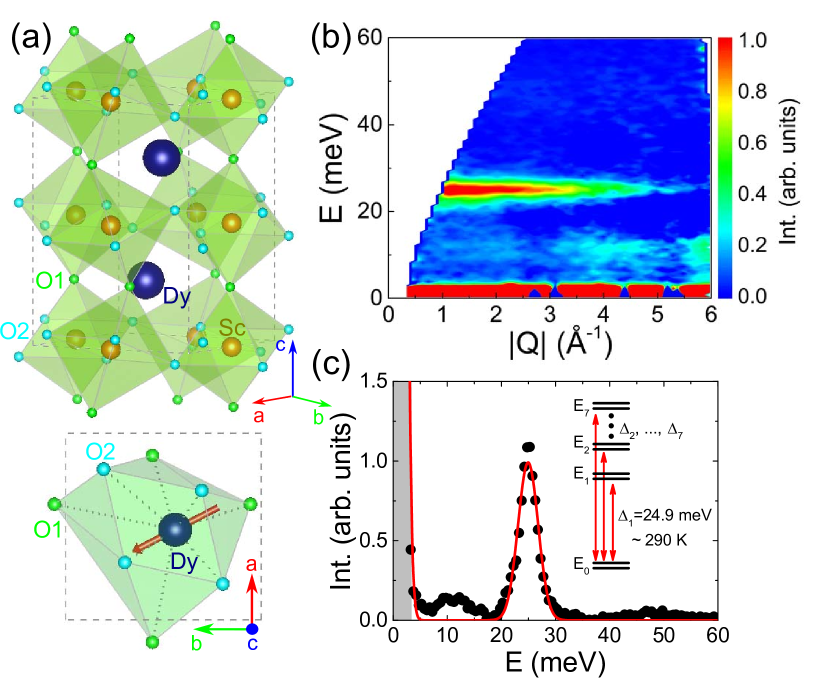
DyScO3 crystallizes in a distorted orthorhombic perovskite structure Liferovich and Mitchell (2004); Uecker et al. (2008). Lattice parameters refined from our powder neutron diffraction data at 10 K are Å, Å, and Å, using the conventional space group (lattice parameters ). The crystal structure of DyScO3 is illustrated in Fig. 1(a), where Dysprosium (Dy) atoms are located between eight distorted Scandium-Oxygen (Sc-O) octahedra. Due to the distortion, the point symmetry of the Dy site is lowered to , with only one mirror plane normal to the -axis. Therefore, Dy3+ moments as constrained by the point symmetry would either point along the -axis, or lie in the -plane. To have a quantitative description of the CEF effect, calculations based on the point charge model Stevens (1952); Hutchings (1964) were performed using the software package McPhase McP . The first twelve nearest Oxygen (O) neighbors around the Dy ion were considered (bottom of Fig. 1(a)), which keep the correct local point symmetry of the Dy site and thus constrain the CEF wave functions. In this local environment, the sixteen fold degenerate (, ) multiplet () of Dy3+ is split into eight doublet states. By local point symmetry, no high-symmetry directions in the mirror plane are present. Therefore, the resulting Ising axis is tilted away from the crystal and axes. The tilting angle is determined by the relative distortion of the nearest oxygen octahedra. We transform the old basis () along the principle crystal () to the new basis (), with defined as the titling angle from the crystal axis:
| old basis | new basis | ||||
The calculated ground doublet states are best diagonalized when the local axis is chosen along the Ising moment easy axis, in which case no imaginary coefficients are left in the ground state wave functions. The tilting angle can be determined with the CEF calculation, by checking the ground state wave function with different values of angle , which results in . The first two Kramers ground state wave functions are given by
The calculated excited levels are located at energies 22.9 meV, 37.6 meV, 43.1 meV, 52.2 meV, 63.3 meV, 79.7 meV, and 98.1 meV. This calculated CEF scheme indicates a well separated ground state doublet, which is almost entirely made up by the wave function . The calculated CEF parameters and matrix elements for transitions between these CEF levels are shown in detail in Appendix IV. The calculated wave functions for the first excited doublet are mostly from , and thus the matrix element for excitations between the ground state and the first excited state is large. However, for higher excited levels, the wave functions are mostly contributed from , , …, , and the matrix elements between the ground state to these higher excited levels are very weak because of the selection rule. Thus, the CEF calculations indicate that only the one excitation to the first excited doublet can be observed at low temperatures by INS, when only the ground state is populated.
The CEF calculations based on the point charge model are well consistent with our INS data. The INS spectrum taken with neutron incident energy meV at K exhibits only one dispersionless excitation as expected, see Fig. 1(b). The scattering intensity of this excitation decreases with increasing wave vector , confirming its magnetic origin. The intensity integrated over a wave vector range Å-1 is shown in Fig. 1(b) as function of the energy transfer . By fitting the peak with a Gaussian function (red solid line), the first excited level was determined to be meV, which is very close to the calculated value.
Since the ground state is well separated from the other excited CEF levels, the low temperature ( K) magnetic properties are dominated by the ground state doublet symmetry. Thus, we could use the low temperature magnetization results to examine the calculated ground state wave function, as will be discussed below in the next section.
III.2 Magnetization
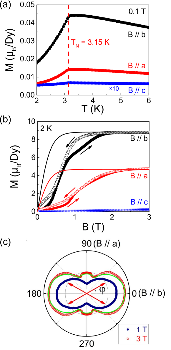
The temperature dependent magnetization of DyScO3 is shown in Fig. 2(a), with the magnetic field applied along the three principle crystallographic axes. A cusp-like anomaly is observed at K for all three directions, indicating the ordering to an antiferromagnetic phase, that is consistent with previous reports Ke et al. (2009); Raekers et al. (2009); Bluschke et al. (2017). The field dependent magnetization measured in the ordered state exhibits a step-like anomaly when the field is applied in the -plane, see Fig. 2(b). The large observed hysteresis indicates subsequent field-induced first order transitions. Significant anisotropy was observed between the -plane and the -axis. The high field saturation moments along and are more than 20 times larger than the moment along the -axis, confirming that the Dy3+ magnetic moments are in the -plane.
To study further the details of the anisotropy, the magnetization was measured in a magnetic field of T and T, with varying direction of the field in the plane. These measurements are shown in Fig. 2(c). A small hump-like feature appears in the magnetization when the applied magnetic field is large enough to polarize the magnetic moments of both Dy sublattices. This is an indication that the moment is tilted relative to the and -axes, as suggested already by the CEF calculations. The angle dependence of the magnetization in a field T can be well described as:
| (1) |
where is the saturation moment, is the angle between the applied field and the -axis, and is the angle between the -axis and the Dy3+ moment direction. The result of this analysis is shown as the green line in Fig. 2c, with /Dy, and , in good agreement with ref. Bluschke et al., 2017. Since the experimental temperature ( K) and magnetic field ( T) are much smaller than the energy scale of the first excited CEF level , it is safe to calculate the field dependent magnetization with the Brillouin function of the ground state doublets, Fig. 2(b). While the saturation at high fields can be well described with a saturation moment /Dy, and an angle , a large mismatch between the measurements and calculations remains at low magnetic field. This suggests additional AF correlations in the system, which are missing in the calculation of the Brillouin function. The magnetization along the -axis can be described with an effective moment /Dy which is consistent with our CEF calculations.
The agreement between the CEF calculations and the magnetization measurements confirms the Ising character of the ground state wave function . The very small magnetization along the -axis also shows that the moments directions are strictly constrained. A direct consequence is that any transverse excitation (spin wave) should be strongly suppressed in DyScO3. The Ising moments are only allowed to fluctuate along their local easy axis, which is reflected in the neutron scattering polarization factor (details to follow below in Section III.5).
III.3 Neutron powder diffraction and magnetic structure
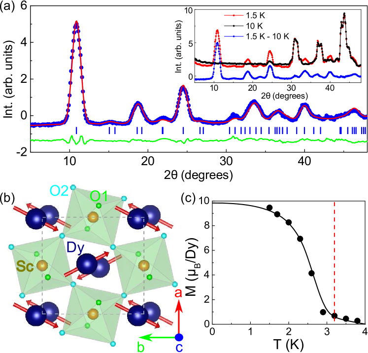
Fig. 3(a) shows the NPD pattern of a crushed single crystal of DyScO3 in the paramagnetic ( K) and magnetically ordered ( K) states. The refined unit cell parameters and atomic positions in the unit cell do agree well with previously reported data for DyScO3 Liferovich and Mitchell (2004). The AF ordering is manifested in appearance of magnetic Bragg reflections below . The symmetry analysis and Rietveld refinement reveal that the magnetic group symmetry is and that the magnetic moments are oriented in the -plane [() representation]. A schematic view of the crystal and magnetic structures of DyScO3 is shown in Fig. 3(b). The temperature dependence of the ordered magnetic moments are presented in Fig. 3(c). A Rietveld refinement of the 1.5 K neutron diffraction dataset reveals that the ordered moments reach and (9.47(6) total). This corresponds to a canting angle of to the -axis. This is in excellent agreement with our CEF calculation and magnetization measurements, and also consistent with earlier studies Raekers et al. (2009); Bluschke et al. (2017).
At temperatures above the ordering transition one can also observe additional diffuse scattering at low angles in the powder patterns, see Fig. 3, indicating short range magnetic correlations and fluctuations above the phase transition. This is studied in better detail with single crystal neutron scattering data which are presented below.
III.4 Magnetic dipole-dipole interaction
In this section we discuss the magnetic ground state in the context of the magnetic dipole-dipole interaction. We have shown that the Dy3+ Ising moments are in the -plane along a direction with an angle relative to the -axis. According to representation analysis, four different magnetic structures (, , and ) with propagation vector are allowed in this case. These four structures are shown in Fig. 4(a). Neutron diffraction shows that DyScO3 selects the configuration. Since the Dy3+-4 electrons are very localized, the 4 exchange interaction is relatively weak. On the other hand, the dipole-dipole interaction is expected to be large due to the extremely large moments in the ground state ( /Dy). Since the dipole-dipole interaction is long range in nature, for each of the four magnetic structures we consider ten near neighbors in total, including eight neighbors within distance Å in the -plane, and two near neighbors at a distance of Å along the -axis. Further neighboring atoms have little influence. The calculated dipole-dipole energies
of the four magnetic structures in zero field are K, K, K, and K, as presented in Fig. 4(b).
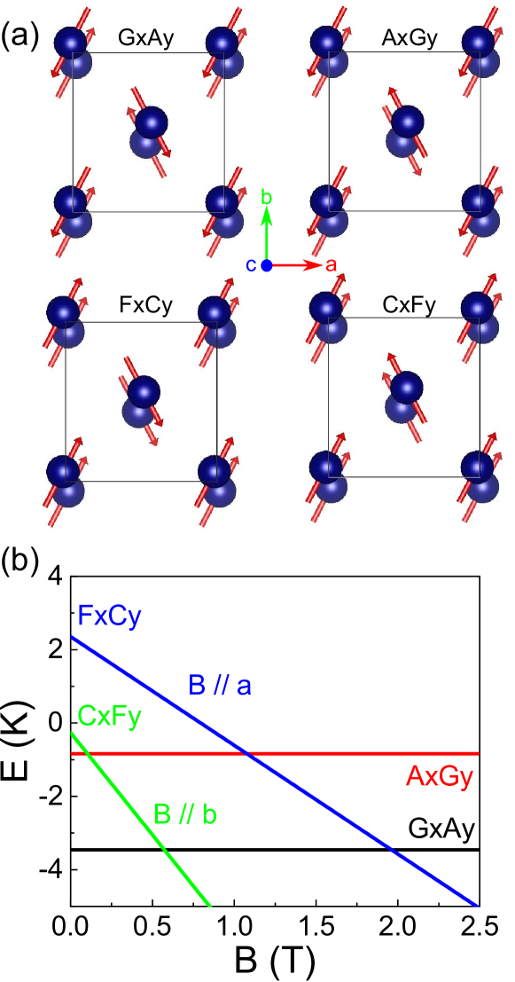
As we can see, the spin configuration has the lowest zero field energy compared with the non-ordered paramagnetic state and the other spin structures. Thus, at zero field the system adopts the ground state, and the AF ordering temperature K is well consistent with the energy scale one estimates from the dipole-dipole interaction. We also note, that the two and configurations would be degenerate if there were no interactions in the -plane. This means that the in-plane interaction lifts the degeneracy and selects the ground state spin configuration. In turn, the in-plane dipolar interaction depends on the relative tilting angle of the Ising moments Kappatsch et al. (1970). Larger value of would switch the ground state from to , as in the case of the isostructural compound YbAlO3 Radhakrishna et al. (1981). Also, if we apply a magnetic field above critical along either the -axis ( T) or the -axis ( T), either or would be the new ground state, stabilized by the Zeeman energy,
where is the number of ions that are summed over the magnetic unit cell. The total field dependent energy of the system is then contributed from both the dipole and Zeeman terms:
as seen in Fig. 2(b). Since the only difference between and (or and ) is the spin arrangement along the -axis, the critical fields give a rough estimate of the interactions along the -axis, which close the gap between the and (or and ) states.
It is also important to note, that the Dy-Dy dipolar interaction between two nearest neighbors along the -direction is K and antiferromagnetic. This is about 2-4 times larger than the corresponding interactions in the -plane, which are ferromagnetic, K and K (corresponding to near neighbor distances of Å and Å in the plane).
III.5 Magnetic diffuse scattering
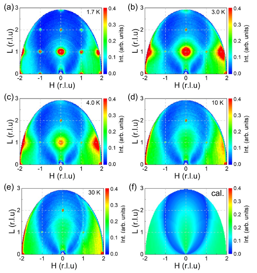
Contour maps of the magnetic neutron scattering in the plane at different temperatures, above and below , show broad diffuse peaks near the magnetic wave vectors and , which are smeared out with increasing temperature (Fig. 5). We have calculated magnetic scattering factor as:
| (2) |
Here, is the transmission for the DyScO3 sample, is the magnetic form factor of Dy3+, is the magnetic structure factor, and is the polarization factor. As discussed earlier, the transverse moment component is very small, . Therefore, we can safely neglect the fluctuations along the transverse direction. Since neutrons scatter only from the component of the magnetic moment that is perpendicular to the wave vector , in the present case the calculated magnetic polarization factor is
| (3) |
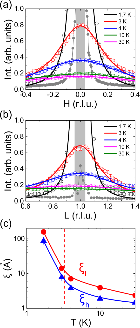
where , and . The neutron transmission factor was explicitly included because of the strong absorption by Dy and Sc. The calculated 1/e absorption length for a 3.32 meV neutron is only about 0.215 mm Patra (2014). The calculated magnetic scattering factor (2) is shown in Fig. 5(f). Good agreement was found with the data taken at 10 K (Fig. 5(d)) and 30 K (Fig. 5(e)). The dip like feature that went through wave vector is due to strong neutron absorption along the plate. We have adopted the lattice Lorentzian function Zaliznyak et al. (2015) to describe the magnetic structure factor:
| (4) |
Here, and are the correlation lengths along the and -axes in units Å.
We show constant energy cuts along wave vector and , integrated over meV, , and in Fig. 6(a) and (b). The fits of the lattice Lorentzian function are shown as solid lines. The temperature dependent correlation lengths from the fits are shown in Fig. 6(c). At temperatures 30 K and 10 K both correlations lengths, along and , are short, much less than one lattice unit. However, as approaching the magnetic ordering temperature, significant correlations build up already at 4 K along both directions, which are greatly enhanced below the ordering temperature. A slight anisotropy was observed between wave vector and , where the correlation along is always larger than that along , as expected from the estimate of the dipolar interactions.
IV Discussion and Conclusion
In summary, the low temperature magnetic properties of DyScO3 hasve been well characterized through a combination of CEF calculations, magnetization, powder and single crystal neutron diffraction measurements. All our results are consistent with an Ising Dy3+ ground state doublet with wave function , where the local easy axis makes an angle of with the -axis. The Dy3+ Ising moments order magnetically at low temperatures ( K), and the AF magnetic ground state is selected mainly by the dipole-dipole interaction.
Strong magnetic diffuse scattering is observed for temperatures up to 30 K, which indicates the persistence of strong critical fluctuations over a wide temperature range. This is rather surprising. Considering that the Ising like moments are rather large, , one would usually expect to see a clean mean-field like transition with very weak critical fluctuation Wu et al. (2011). Critical fluctuations could be enhanced by the low dimensionality, as seen in other rare-earth based one-dimensional systems Wu et al. (2016); Miiller et al. (2016).
No inelastic excitations have been observed at all in DyScO3 below the first excited CEF level. To understand this puzzling observation, one may go back to the ground state wave function. First, one notes that any inelastic scattering due to transverse fluctuations should be strongly suppressed. Because of the strong Ising like single ion anisotropy, which can be quantified as , the neutron scattering intensity due to transverse fluctuations is expected to be about two orders of magnitude smaller than the scattering intensity from longitudinal fluctuations, , at temperatures and fields smaller the the first CEF excited level . Thus, any fluctuations along the transverse direction, such as spin waves, would be extremely weak. One would then expect to see strong fluctuations along the longitudinal directions from the Dy3+ Ising moments. In the most general case the ground state wave function can be expressed as
| (5) |
Comparing to the calculated ground state wave function, see above, we see that most of these contributions are missing () due to the constraint of the point site symmetry. Therefore, any Hamiltonian matrix element, which connects the ’up’ and ’down’ states of moment is absent. This indicates that neutrons can neither flip the Dy3+ ground Ising moments nor propagate them, due to the selection rule . In other words, in the case of DyScO3, these possible spinon excitations along the longitudinal directions are ’hidden’ to neutrons. It is interesting to notice that a splitting of ground-state was observed in the optical absorption spectra of the related DyAlO3 compound Schuchert et al. (1969), which was claimed to originate from the one-dimensional interactions along the -axis. Further studies using other direct or indirect techniques, such as ac-susceptibility, or optical absorption, for which such selection rules don’t apply, would be needed to reveal the ’hidden’ low-energy dynamics.
Acknowledgements.
We thank J. M. Sheng and Q. Zhang for the help with the neutron data refinement. We would like to thank A. Christianson, I. Zaliznyak, M. Mourigal, Z. T. Wang, and C. Batista for useful discussions. The research at the Spallation Neutron Source (ORNL) is supported by the Scientific User Facilities Division, Office of Basic Energy Sciences, U.S. Department of Energy (DOE). Research supported in part by the Laboratory Directed Research and Development Program of Oak Ridge National Laboratory, managed by UT-Battelle, LLC, for the U.S. Department of Energy. This work was partly supported by the U.S. Department of Energy (DOE), Office of Science, Basic Energy Sciences (BES), Materials Science and Engineering Division.Appendix A Point charge model calculations
A point charge model considers crystalline electric field effects as a perturbation to the appropriate free-ion wave functions and energy levels and the perturbed crystalline potential energy may be rewritten as:
| (6) |
where and are charges of magnetic ions and ligand ions, is the sum over all neighbor charges Hutchings (1964) and is the distance between magnetic ion and ligand charge. The calculated first excited state is
The calculated CEF parameters from the point charge model and resulting the energy levels are shown in Table 1 and 2 below, respectively.
| (meV) | ||
|---|---|---|
| 22.9 | 8.2 | |
| 37.6 | 0.1 | |
| 43.1 | 0.02 | |
| 52.2 | 0.05 | |
| 63.3 | 0.02 | |
| 79.7 | 0 | |
| 98.1 | 0 |
References
- Cohen (1992) R. E. Cohen, “Origin of ferroelectricity in perovskite oxides,” Nature 358, 136 (1992).
- Lee et al. (2011) Jung-Hoon Lee, Young Kyu Jeong, Jung Hwan Park, Min-Ae Oak, Hyun Myung Jang, Jong Yeog Son, and James F. Scott, “Spin-Canting-Induced Improper Ferroelectricity and Spontaneous Magnetization Reversal in ,” Phys. Rev. Lett. 107, 117201 (2011).
- Cheong and Mostovoi (2007) S-W. Cheong and M. Mostovoi, “Multiferroics: a magnetic twist for ferroelectricity,” Nature Mater. 6, 13 (2007).
- Khomskii (2009) D. Khomskii, “Classifying multiferroics: Mechanisms and effects,” Physics 2, 20 (2009).
- Belov et al. (1976) K. P. Belov, A. K. Zvezdin, A. M. Kadomtseva, and R. Z. Levitin, “Spin-reorientation transitions in rare-earth magnets,” Sov. Phys. Usp. 19, 574 (1976).
- Kimel et al. (2009) A. V. Kimel, B. A. Ivanov, R. V. Pisarev, P. A. Usachev, A. Kirilyuk, and Th. Rasing, “Inertia-driven spin switching in antiferromagnets,” Nature Phys. 5, 727 (2009).
- Mourigal et al. (2013) M. Mourigal, M. Enderle, A. Klöpperpieper, J.-S. Caux, A. Stunault, and H. M. Rønnow, “Fractional spinon excitations in the quantum Heisenberg antiferromagnetic chain,” Nature Physics 9, 435 (2013).
- White (1969) R. L. White, “Review of Recent Work on the Magnetic and Spectroscopic Properties of the Rare-Earth Orthoferrites,” J. Appl. Phys. 40, 1061 (1969).
- Tokunaga et al. (2008) Y. Tokunaga, S. Iguchi, T. Arima, and Y. Tokura, “Magnetic-Field-Induced Ferroelectric State in ,” Phys. Rev. Lett. 101, 097205 (2008).
- Ke et al. (2009) X. Ke, C. Adamo, D. G. Schlom, M. Bernhagen, R. Uecker, and P. Schiffer, “Low temperature magnetism in the perovskite substrate DyScO3,” Appl. Phys. Lett. 94, 152503 (2009).
- Raekers et al. (2009) M. Raekers, K. Kuepper, S. Bartkowski, M. Prinz, A. V. Postnikov, K. Potzger, S. Zhou, A. Arulraj, N. Stüßer, R. Uecker, W. L. Yang, and M. Neumann, “Electronic and magnetic structure of (,Gd,Dy) from x-ray spectroscopies and first-principles calculations,” Phys. Rev. B 79, 125114 (2009).
- Bluschke et al. (2017) M. Bluschke, A. Frano, E. Schierle, M. Minola, M. Hepting, G. Christiani, G. Logvenov, E. Weschke, E. Benckiser, and B. Keimer, “Transfer of Magnetic Order and Anisotropy through Epitaxial Integration of and Spin Systems,” Phys. Rev. Lett. 118, 207203 (2017).
- Radhakrishna et al. (1981) P. Radhakrishna, J. Hammann, M. Ocio, P. Pari, and Y. Allain, “Antiferromagnetic ordering in the ytterbium aluminum perovskite YbAlO3,” Solid State Communications 37, 813 – 817 (1981).
- Knížek et al. (2014) K. Knížek, Z. Jirák, P. Novák, and C. R. dela Cruz, “Non-collinear magnetic structures of TbCoO3 and DyCoO3,” Solid State Sci. 28, 26–30 (2014).
- Jirák et al. (2014) Z. Jirák, J. Hejtmánek, K. Knížek, P. Novák, E. Šantavá, and H. Fujishiro, “Magnetism of perovskite cobaltites with kramers rare-earth ions,” J. Appl. Phys. 115, 17E118 (2014).
- Schuchert et al. (1969) H. Schuchert, S. Hüfner, and R. Faulhaber, “Optical Investigation of Metamagnetic DyAlO3,” Z. Physik 222, 105 (1969).
- Choi et al. (2004) K. J. Choi, M. Biegalski, Y. L. Li, A. Sharan, J. Schubert, R. Uecker, P. Reiche, Y. B. Chen, X. Q. Pan, V. Gopalan, L.-Q. Chen, D. G. Schlom, and C. B. Eom, “Enhancement of Ferroelectricity in Strained BaTiO3 Thin Films,” Science 306, 1005–1009 (2004).
- Schlom et al. (2007) D. G. Schlom, L-Q. Chen, Ch-B. Eom, K. M. Rabe, and S. K. Streiffer. J-M. Triscone, “Strain tuning of ferroelectric thin films,” Annu. Rev. Mater. Res. 37, 589 (2007).
- Granroth et al. (2010) G. E. Granroth, A. I. Kolesnikov, T. E. Sherline, J. P. Clancy, K. A. Ross, J. P. C. Ruff, B. D. Gaulin, and S. E. Nagler, “SEQUOIA: a newly operating chopper spectrometer at the SNS,” J. Phys.: Conf. Ser. 251, 012058 (2010).
- Stone et al. (2014) M. B. Stone, J. L. Niedziela, D. L. Abernathy, L. DeBeer-Schmitt, G. Ehlers, O. Garlea, G. E. Granroth, M. Graves-Brook, A. I. Kolesnikov, A. Podlesnyak, and B. Winn, “A comparison of four direct geometry time-of-fight spectrometers at the Spallation Neutron Source,” Rev. Sci. Instrum. 85, 045113 (2014).
- Ehlers et al. (2011) G. Ehlers, A. Podlesnyak, J. L. Niedziela, E. B. Iverson, and P. E. Sokol, “The new cold neutron chopper spectrometer at the Spallation Neutron Source: design and performance,” Rev. Sci. Instrum. 82, 085108 (2011).
- Ehlers et al. (2016) G. Ehlers, A. Podlesnyak, and A.I Kolesnikov, “The cold neutron chopper spectrometer at the Spallation Neutron Source — A review of the first 8 years of operation,” Rev. Sci. Instrum. 87, 093902 (2016).
- Rodríguez-Carvajal (1993) Juan Rodríguez-Carvajal, “Recent advances in magnetic structure determination by neutron powder diffraction,” Physica B: Cond. Matter 192, 55 (1993).
- Wills (2000) A. S. Wills, “A new protocol for the determination of magnetic structures using simulated annealing and representational analysis (SARAh),” Physica B: Cond. Matter 276, 680 (2000).
- Arnold et al. (2014) O. Arnold, J. C. Bilheux, J. M. Borreguero, A. Buts, S. I. Campbell, L. Chapon, M. Doucet, N. Draper, R. Ferraz Leal, M. A. Gigg, V. E. Lynch, A. Markvardsen, D. J. Mikkelson, R. L. Mikkelson, R. Miller, et al., “Mantid–Data analysis and visualization package for neutron scattering and SR experiments,” Nucl. Instrum. Methods A 764, 156 (2014).
- Azuah et al. (2009) R. Azuah, L. Kneller, Y. Qiu, P. Tregenna-Piggott, C. Brown, J. Copley, and R. Dimeo, “DAVE: a comprehensive software suite for the reduction, visualization, and analysis of low energy neutron spectroscopic data,” J. Res. Natl. Inst. Stan. Technol. 114, 341 (2009).
- Liferovich and Mitchell (2004) R. P. Liferovich and R. H. Mitchell, “A structural study of ternary lanthanide orthoscandate perovskites,” J. Solid State Chem. 177, 2188 (2004).
- Uecker et al. (2008) R. Uecker, B. Velickov, D. Klimm, R. Bertram, M. Bernhagen, M. Rabe, M. Albrecht, R. Fornari, and D.G. Schlom, “Properties of rare-earth scandate single crystals (re=nd−dy),” Journal of Crystal Growth 310, 2649 – 2658 (2008).
- Stevens (1952) K. W. H. Stevens, “Matrix elements and operator equivalents connected with the magnetic properties of rare earth ions,” Proc. Phys. Soc. A 65, 209 (1952).
- Hutchings (1964) M. T. Hutchings, “Point-charge calculations of energy levels of magnetic ions in crystalline electric fields, in: Soild state physics: Advances in research and applications,” (Academic Press, N.Y., 1964).
- (31) http://www.mcphase.de; M. Rotter, J. Magn. Magn. Mater. 272-276, E481 (2004).
- Kappatsch et al. (1970) A. Kappatsch, S. Quezel-Ambrunaz, and J. Sivardière, “Structures et propriétés magnétiques des orthocobaltites de terres rares ,” Journal de Physique 31, 369–376 (1970).
- Patra (2014) A. Patra, Study of reactor constitutive model and analysis of nuclear reactor kinetics by fractional calculus approach, Ph.D. thesis (2014).
- Zaliznyak et al. (2015) I. Zaliznyak, A.T. Savici, M. Lumsden, A. Tsvelik, R. Hu, and C. Petrovic, “Spin-liquid polymorphism in a correlated electron system on the threshold of superconductivity.” PNAS 112, 10316–10320 (2015).
- Wu et al. (2011) L. S. Wu, Y. Janssen, C. Marques, M. C. Bennett, M. S. Kim, K. Park, S. Chi, J. W. Lynn, G. Lorusso, G. Biasiol, and M. C. Aronson., “Magnetic field tuning of antiferromagnetic ,” Phys. Rev. B. 84, 134409 (2011).
- Wu et al. (2016) L. S. Wu, W. J. Gannon, I. A. Zaliznyak, A. M. Tsvelik, M. Brockmann, J.-S. Caux, M. S. Kim, Y. Qiu, J. R. D. Copley, G. Ehlers, A. Podlesnyak, and M. C. Aronson, “Orbital-exchange and fractional quantum number excitations in an f-electron metal, Yb2Pt2Pb,” Science 352, 1206 (2016).
- Miiller et al. (2016) W. Miiller, L. S. Wu, M. S. Kim, T. Orvis, J. W. Simonson, M. Gamża, D. M. McNally, C. S. Nelson, G. Ehlers, A. Podlesnyak, J. S. Helton, Y. Zhao, Y. Qiu, J. R. D. Copley, J. W. Lynn, I. Zaliznyak, and M. C. Aronson, “Magnetic structure of : Ising moments on the Shastry-Sutherland lattice,” Phys. Rev. B 93, 104419 (2016).