A multi-GHz chaotic optoelectronic oscillator based on laser terminal voltage
Abstract
A multi-GHz chaotic optoelectronic oscillator based on an external cavity semiconductor laser (ECL) is demonstrated. Unlike standard optoelectronic oscillators for microwave applications, we do not employ the dynamic light output incident on a photodiode to generate the microwave signal, but instead generate the microwave signal directly by measuring the terminal voltage of the laser diode of the ECL under constant-current operation, thus obviating the photodiode entirely.
Microwave signals are commonly used in communications, radar, and medical imaging. High-frequency microwave waveforms are conventionally generated in the electrical domain using digital electronics and typically involve several stages of multipliers and amplifiers. This approach, however, may be inefficient at high frequencies. Another possibility is to generate microwave waveforms in the optical domain, to take advantage of the broad bandwidth and low attenuation in the optical system. Optical generation of microwave signals enables tremendous flexibility; the optical signal can be converted immediately to a microwave electrical signal via a fast photodiode (PD) or can be transmitted over low-loss optical fiber systems to be converted downstream to a microwave electrical signal.
Specific implementations of such optoelectronic oscillators (OEOs) can be based on the beating of two phase-locked optical wavesyao1 ; yao2 , through OEOs based on optical injection of a master laser into a slave laser15Nelson or electro-optic modulators96Yao ; 10Chembo have been demonstrated. Moreover, on-chip OEO miniaturization and integration is possiblemalekiNP , providing a further desirable feature of OEOs.
In addition to the interest in optical microwave generation of periodicyao1 and shaped-pulse yao2 signals, there has also been a stream of work on the generation of broadband chaotic signals through the use of electro-optic modulators subjected to feedback96Celka ; 02Goedg of a laser diode (LD) subjected to optoelectronic01JMLiu or optical feedback92Mork ; 95Celka (ECL), or to optical injection97Simpson ; kuwashima3 . It is notable that certain applications13Soriano of chaotic laser dynamics, and in particular chaotic radar9 and ultrahigh-rate random-bit generation 6 ; 7 ; nianqiang1 , do not intrinsically make use of the chaotic optical signal, but of an electrical signal detected by one or more PDs. These comments also apply for the work cited above on the generation of periodic microwave signals: a PD separate from the LD is always necessary to create an electrical signal while the optical signal itself is often not used directly [unless low-loss optical transmission of the signal is needed prior to optical-to-electrical (O/E) conversion]. Clearly, circumventing O/E conversion could significantly simplify various applications of such chaotic signals.
In this letter, we demonstrate a chaotic multi-GHz OEO based on an ECL with direct chaotic microwave electrical generation. In other words, our approach entirely obviates the use of a PD by directly monitoring the time-dependent voltage across the injection terminals of the laser diode under constant-current injection. We verify that the dynamics exhibited by is indeed chaotic and of comparable dynamical complexity as that of by means of a largest-Lyapunov-exponent (LLE) analysis. The basis for our observation is that for small signals, is proportional to the inversion in the gain medium, as was pointed out in Refs. kazarinov, ; sahai, ; Roy, . The dynamics of and , in turn, are closely linked, as is understood, for example, on the basis of the Lang-Kobayashi equations lk . Ref. FischerTomo, recently showed a measurement of the voltage across the LD but focused uniquely on its use, in conjunction with a phase measurement, to describe and understand the regime of low-frequency fluctuations.
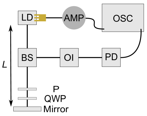
The experimental setup is shown in Fig. 1. The single longitudinal-mode edge-emitting InGaAsP multi-quantum-well DFB LD emits at 1550 nm with free-running threshold current mA. The heterostructure, containing 7 quantum wells, and the grating are designed and fabricated to achieve a product of 50 cm-1 and the length of the laser diode is measured to be mm, resulting in a value of . The detailed structure has been described and investigated for feedback tolerance in Ref. AnthonyAPL, . The experimental feedback strength is determined by the relative angle between the polarizer and the quarter-wave plate (QWP), where corresponds to maximum feedback strength (16 % of the optical power that is coupled back onto the collimating lens). The QWP is mounted on a motorized rotational stage with a step size of . During the experiment, a RF probe (Cascade Microtech AE-ACP40-GSG-400) with bandwidth of 40 GHz is used to extract from the LD injection terminals. The AC component of is separated from the DC component with a bias tee (Keysight 11612A), and then amplified with an 18-dB amplifier (Newport 1422-LF) with 20 GHz bandwidth. The AC components of intensity, and voltage, are both captured by a real-time oscilloscope (Agilent DSO80804B) whose cut-off frequency is 12 GHz. The external cavity length is chosen to be 30, 42, or 70 cm corresponding to external cavity round-time , 2.80, or 4.67 ns and giving an external-cavity free-spectral range of , 0.35, or 0.21 GHz, respectively.
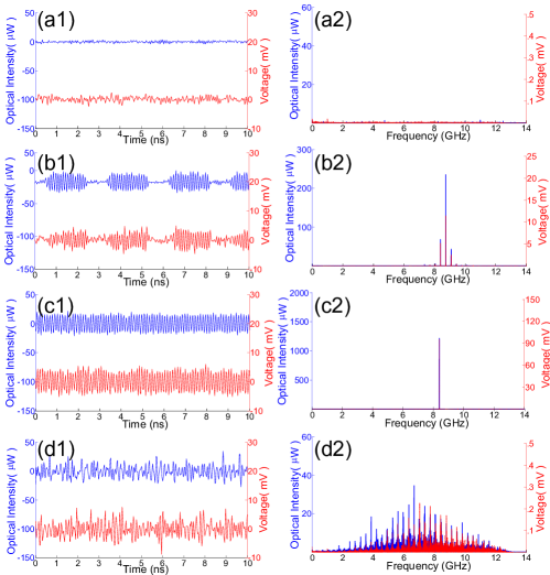
Figure 2 shows and with their RF spectra for various at mA and cm via FFT of the original time series. Under these conditions, the relaxation-oscillation frequency, GHz and GHz. Both and are extracted simultaneously from the oscilloscope and synchronized precisely by calibrating the time delay in the optical versus the electrical path. We observe that the ECL experiences a range of dynamical regimes (CW, periodic, quasi-periodic, and chaotic) and can be accessed both from the optical intensity and the laser voltage. We also observe, as expected, that and are typically highly anticorrelated on the timescale of as carriers recombine to emit photons thereby reducing .
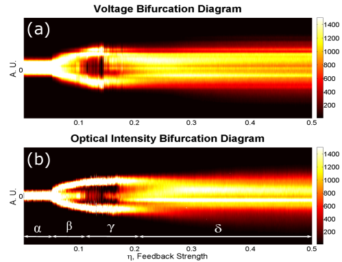
Figure 3 shows the simultaneously measured bifurcation diagrams (BDs) for and . BDs have been obtained recently for the optical alonebobbyOE ; bobbyPRA . Each BD is obtained by plotting the density of local extrema of the corresponding time series as the is increased. In both BDs, the density is high in white but low in black. Both Figs. 2 and 3 indicate the dynamical regime of the ECL bobbyPRA .
The simultaneous examination of Figs. 2 and 3 reveals the broad range of dynamical behaviors of an ECL-based OEO. In the following, without going into the details of all the bifurcations experienced by the ECL, we present the structurally stable dynamical regimes, i.e. those that remain qualitatively the same in a large region of values of . When , corresponding to region in Fig. 3(b), the ECL is in continuous-wave (CW) operation. Fig. 2(a) further illustrates that the noise level is of similar magnitude on and , though slightly larger on the voltage.
Region in Fig. 3(b) shows quasi-periodic behavior of the ECL, which is confirmed by the spectra of and that both show the presence of two incommensurate frequencies, in the form of a central peak at 8.74 GHz, and sidebands offset by 0.35 GHz from the central peak. This quasi-periodic behavior is expected to occur on the route to chaos for an ECL92Mork , where the central peak frequency is close to that of the relaxation-oscillation frequency and that the side-peak separation is close to . The undamping of these two frequencies probably results from two successive Hopf bifurcation in Ref. 92Mork, and Ref. bobbyPRA, . Periodic dynamics are observed within region , and in Fig. 2(c), where a single peak dominates the RF spectrum. In this case, the peak is at GHz, reflecting plus , as already observed in Ref. bobbyPRA, in the case of a multi-quantum-well laser. The observation of such periodic windows in the route to chaos is consistent with previous reports Ref. 92Mork, and Ref. bobbyPRA, of periodic windows in the quasi-periodic route to chaos in an ECL. Moreover, the observed frequency of GHz in region , reflecting , is also consistent with our previous conclusion in Ref. bobbyPRA, .
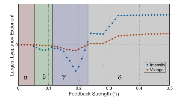
As we further increase the feedback strength above , we enter region of the BDs (Fig. 3), and reveal an apparently erratic behavior [Fig. 2(d1)] and the corresponding spectra show considerable broadening [Fig. 2(d2)], as the 6 dB bandwidth is approximately GHz. The suspected chaotic behavior in region is confirmed by evaluating the (LLE) from the time series of both and HeggerLLE ; KantzPRA ; KantzLLE . In Fig. 4, the value of LLE is plotted as a function of feedback strength for both optical intensity and voltage. We obtain consistently a (strictly) positive and similar value of the LLE from the analysis of or in region (), confirming the chaotic nature of the dynamical behavior. Although further work must be carried out, these results indicate that both and exhibit comparable chaotic characteristics. Moreover, we observe an increase of the LLE with , indicating tunability of chaos complexity in the proposed OEO. Although not shown here, we have further confirmed the robustness of these observations by resolving BDs for various values of (30, 42, and 70 cm) and (50, 60, and 70 mA) which enables further tunability of the RF spectrum and chaos complexity. In region , the bandwidth of where the ECL is in coherence collapse (well developed chaos) extends up to 8GHz.
As ECLs are recognized as being simple and inexpensive sources of high-dimensional chaosFischerPRL , as is of interest for applications such as chaos radar 9 and ultrahigh rate random-bit generation 6 ; 7 ; nianqiang1 , our work demonstrates the ability to generate such microwave signals directly, and not requiring O/E conversion. In conclusion, we have demonstrated a multi-GHz OEO that entirely circumvents the need for O/E conversion. We have shown that the voltage across the LD allows for the robust generation of periodic, quasi-periodic, as well as chaotic oscillations, of various complexity, that have similar characteristics to those obtained from the optical intensity.
We gratefully acknowledge the financial support of the 2015 Technologies Incubation scholarship from Taiwan Ministry of Education, the Conseil Regional de Lorraine, and the Fonds European de Developement Regional (FEDER).
References
- (1) J. Yao, Internat. J. Microwave Opt. Technol. 5, 16 (2010).
- (2) J. Yao, Opt. Commun. 284, 3723 (2011).
- (3) J. P. Zhuang and S. C. Chan, Opt. Exp. 23, 2777 (2015).
- (4) X. S. Yao and L. Maleki, Opt. Lett. 21, 483 (1996).
- (5) K. Volyanskiy, P. Salzenstein, H. Tavernier, M. Pogurmirskiy, Y. K. Chembo, and L. Larger, Opt. Exp. 18, 22358 (2010).
- (6) L. Maleki, Nat. Photon. 5, 728 (2011).
- (7) P. Celka, IEEE Trans. Circuits Syst. I 43, 869 (1996).
- (8) J. P. Goedgebuer, P. Levy, L. Larger, C. C. Chen, and W. T. Rhodes, IEEE J. Quantum Electron. 38, 1178 (2002).
- (9) S. Tang and J. M. Liu, IEEE J. Quantum Electron. 37, 329 (2001).
- (10) J. Mork, B. Tromborg, and J. Mark, IEEE J. Quantum Electron. 25, 123 (1988).
- (11) P. Celka, IEEE Trans. Circuits Syst. I 42, 455 (1995).
- (12) F. Kuwashima, The Review of Laser Engineering 43, 381 (2015).
- (13) T. B. Simpson, J. M. Liu, K. F. Kuang, and K. Tai, Quantum Semiclass. Opt. 9, 765 (1997).
- (14) M. C. Soriano, J. Garcia-Ojalvo, C. R. Mirasso, and I. Fischer, Rev. Mod. Phys. 85, 421 (2013).
- (15) F. Y. Lin and J. M. Liu, IEEE J. Quantum Electron. 40, 815 (2004).
- (16) A. Uchida, K. Amano, M. Inoue, K. Hirano, S. Naito, H. Someya, I. Oowada, T. Kurashige, M. Shiki, S. Yoshimori, K. Yoshimura, and P. Davis, Nat. Photon. 2, 728 (2008).
- (17) K. Hirano, T. Yamazako, S. Morikatsu, H. Okumura, H. Aida, A. Uchida, S. Yoshimori, K. Yoshimura, T. Harayama, and P. Davis, Opt. Exp. 18, 5512 (2010).
- (18) N. Li, B. Kim, V. N. Chizhevsky, A. Locquet, M. Bloch, D. S. Citrin, and W. Pan, Opt. Exp. 22, 6634 (2014).
- (19) R. F. Kazarinov and R. Suris, Sov. Phys.JETP 39, 522 (1974).
- (20) A. A. Sahai, B. Kim, D. Choi, A. Locquet, and D. S. Citrin, Opt. Lett. 39, 5630 (2014).
- (21) W. Ray, W. Lam, P. N. Guzdar, and R. Roy, Phys. Rev. E 73, 026219 (2006).
- (22) R. Lang and K. Kobayashi, IEEE J. Quantum Electron. 16, 347 (1980).
- (23) D. Brunner, M. C. Soriano, X. Porte, and I. Fischer, Phys. Rev. Lett. 115, 053901 (2015).
- (24) Q. Zou, K. Merghem, S. Azouigui, A. Martinez, A. Accard, N. Chimot, F. Lelarge, and A. Ramdane, Appl. Phys. Lett. 97, 231115 (2010)
- (25) B. Kim, A. Locquet, D. Choi, and D. S. Citrin, Phys. Rev. A 91, 061802(R) (2015).
- (26) B. Kim, N. Li, A. Locquet, and D. S. Citrin, Opt. Exp. 22, 2348(2014).
- (27) R. Hegger, HK̇antz, and T. Schreiber, CHAOS 9, 413 (1999)
- (28) H. Kantz, Phys. Lett. A 185, 77 (1994).
- (29) H. Kantz and T. Schreiber, Nonlinear Time Series Analysis, 2nd edition, Cambridge University Press, Cambridge (2004).
- (30) I. Fischer. and O. Hess, W. Elsäer, and E. Göbel, Phys. Rev. Lett. 73, 2188 (1994).