Tunable X-band optoelectronic oscillators based on external-cavity semiconductor lasers
Abstract
Laser diodes with optical feedback can exhibit periodic intensity oscillations at or near the relaxation-oscillation frequency. We demonstrate optoelectronic oscillators based on external-cavity semiconductor lasers in a periodic dynamical regime tunable over the entire X-band. Moreover, unlike standard optoelectronic oscillators, we need not employ the time-dependent optical intensity incident on a photodiode to generate the microwave signal, but rather have the option of generating the electrical microwave signal directly as a voltage at the laser-diode injection terminals under constant current operation; no photodiode need be involved, thus circumventing optical-to-electrical conversion. We achieve a timing jitter of ps and a quality factor of across the entire X-band, that ranges from 6.79 GHz to 11.48 GHz. Tuning is achieved by varying the injection current .
I Introduction
Microwave optoelectronic oscillators (OEO) have attracted attention due to the tunability and stability of low-power laser diodes (LD) (williamson, ; maleki, ). OEOs enable tremendous flexibility; the optical signal can be converted immediately to a microwave electrical signal via a fast photodiode (PD) or can be transmitted over low-loss optical fiber to be converted downstream to a microwave electrical signal, again by a PD.
There are several approaches to achieving OEOs. One common approach is to beat two phase-locked optical waves (yao1, ; yao2, ); others are based on optical injection of a master laser into a slave laser (15Nelson, ) or electro-optic modulators (96Yao, ; 10Chembo, ).
While in some implementations, the optical signal is used to convey the microwave information for later optical-to-electrical (O/E) conversion, for a number of applications, the optical signal [time-dependent optical intensity ] itself is of no intrinsic interest. Instead, O/E conversion is carried out proximate to the optical generation by one or more PDs. Nonetheless, in all cases of which we are aware, a PD separate from the LD is required to generate the electrical signal. Eliminating the O/E conversion, therefore, would be a simplification in a large class of OEO-based systems.
We point the way to do so. This work demonstrates an OEO based on an external-cavity semiconductor laser (ECL) in which the microwave electrical signal is generated directly by monitoring the voltage across the injection terminals of the LD under constant-current conditions; in addition, the periodic optical intensity may also be used for microwave generation if so desired. An approach extracting electrical microwave signals in an OEO has been demonstrated in Ref. (IEEEPTLZhao, ) in a structure incorporating an electroabsorption modulated laser (EML). We point out that in our case, no EML is required; the direct optical feedback onto the LD produces spontaneous intensity oscillations. In broad terms, in a periodic dynamical regime in an ECL, oscillations in and occur that are out of phase (though the true dynamics as predicted by the Lang-Kobayashi equations (lk, ) are somewhat different), i.e., one observes undamped relaxation oscillations at frequency . With the monotonic dependency of on the injection current, the tunability across the entire X-band is achieved by varying the injection current . As is well known, is directly related to the inversion in the LD active region (74kazarinov, ; 14sahai, ; 06Roy, ). We find, for our LD, that the amplitude of the oscillations in is around 278 , the oscillation frequency is tunable from 6.79 to 11.48 GHz (the upper limit here is due to the frequency cutoff of our oscilloscope). The oscillation frequency is created by a Hopf bifurcation of an external-cavity mode. It has been shown that its frequency close to the relaxation-oscillation frequency depends on the pumping current, and the feedback strength (YarivOxford, ; CohenJQE, ; AcketJQE, ). Typical values of the timing jitter are ps, and the quality factor is . The combination of wide tunability and low noise figures of merit may make this device competitive with state-of-the art OEOs.
II Experiment
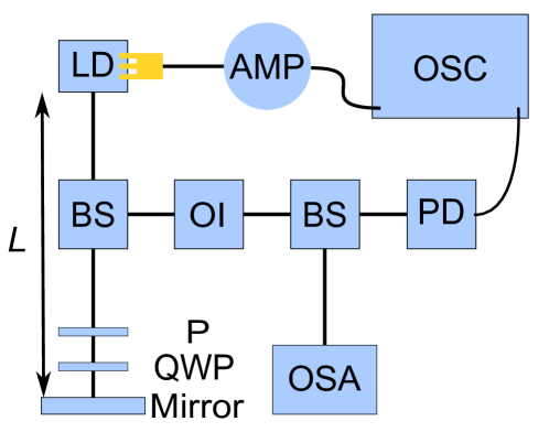
A schematic diagram of the experiment is illustrated in Fig. 1. The ECL is based on a single longitudinal-mode edge-emitting InGaAsP DFB LD containing seven quantum-wells in the active region. The grating is designed and fabricated to achieve a factor of 50 cm-1 and the length of the LD is measured to be 0.6 mm, resulting in a value of 3. The LD emits at 1550 nm with free-running threshold current mA. The structure has been described in detail and investigated for feedback tolerance in Ref. (AnthonyAPL, ). For the ECL, the experimental feedback strength is determined by the relative angle between a polarizer (P) and a quarter-wave plate (QWP) in Fig. 1. The maximum feedback strength corresponds to 16 % of the optical power being coupled back onto the collimating lens. The QWP is mounted on a motorized rotational stage with a step size of . For the measurement of , a RF probe (Cascade Microtech AE-ACP40-GSG-400) with 40-GHz bandwidth is employed to extract from the LD injection terminals. The AC and DC components of are separated with a bias tee (Keysight 11612A), and amplified with an 18-dB amplifier (Newport 1422-LF) with 20 GHz bandwidth. In addition, the AC component of and are simultaneously recorded on a real-time oscilloscope (OSC) (Agilent DSO80804B) with 12 GHz cut-off frequency. An optical spectrum analyzer (BOSA 400) is used to detect the purity of the optical signal. The external cavity length is chosen to be 42, 68, or 94 cm, corresponding to an external cavity round-trip time of 2.8, 4.5, or 5.9 ns and giving an external-cavity free-spectral range of 0.36, 0.22, or 0.17 GHz.
III Results and Discussion

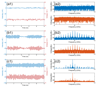
The various dynamical regimes (including chaos) accessed by our ECL are amply discussed in Ref. (CYCAPL, ) to which we refer the interested reader. Our aim here is to focus on the regime in which and are periodic. To illustrate the progression from CW operation to periodic oscillations, in Fig. 2 are shown simultaneous time series for and with the corresponding RF spectra for various at mA and cm ( GHz), where GHz. Moving down Fig. 2, increases: . For very low , the ECL output is similar to that of the solitary LD showing CW behavior. Here, both and are relatively constant apart from noise originating in part from spontaneous emission. As is increased to 0.19, the ECL has entered a quasi-periodic regime. The dynamics are dominated by the beating GHz with GHz as seen in Fig. 2(b1). The RF spectra of Fig. 2(b2) for and are both peaked at with sidebands separated from the maximum by multiples of . For larger , a periodic dynamical regime is finally accessed [Fig. 2(c1)]; this is the dynamical regime of interest to the present study. Here both and are highly periodic; the RF spectra [Fig. 2(c2)] have narrowed considerably as compared with Fig. 2(b2). Figure 2(c2) shows that the spectrum of the periodic signal is characterized by a dominant main peak at GHz and sidebands separated by . Also, and are out of phase reflecting the interchange of optical and material excitation due to relaxation oscillations.
We now focus on the case when mA, where the relaxation-oscillation frequency GHz, cm ( GHz), and . In addition, we heretofore concentrate on , though similar dynamics are exhibited in . A typical time series for is shown in Fig. 3(a) mA, cm, and 0.19. Also shown is a sinusoid fit to the measured time series. The signal is seen to be highly periodic, though contains both amplitude and timing jitter (see below for quantitative characterization). Note that this signal has been amplified with a gain 18 dB, which may increase jitter. The RF spectrum [Fig. 3(b)] is narrow and centered on GHz with weak sidebands separated by . In Fig. 3(c), we present the optical spectrum of and observe that one external cavity mode (ECM) dominates. This is the 6th ECM mode to the right of the minimum linewidth mode(bobbyOE, ; bobbyPRA, ). Its frequency is of 1.39 GHz on the optical-frequency scale of Fig. 3(c) corresponding to an ECM at 1552.07 nm (193.33 THz).
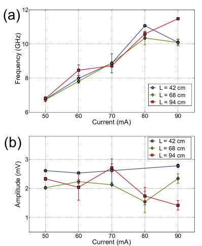
We have carried out similar measurements for , , , , and mA and , 68, and 94 cm. Figure 4(a) shows the center frequency as a function of for , 68, and 94 cm with . We see that with ECLs based on this single LD, tunability between 6.79 to 11.48 GHz is achievable. Thanks to the strong variation of the relaxation-oscillation frequency of a laser diode with the injection current (YarivOxford, ). The upper frequency cutoff, however, corresponds to the bandwidth of our oscilloscope; independent measurements of for this LD (AnthonyAPL, ) show as high as 13 GHz. Moreover, Fig. 4(b) shows that after amplification (18 dB), electrical signals with few-millivolt rms peak value are consistently obtained.
| System | Fabry-Perot | Bragg Grating | Optical Filter | Our System |
|---|---|---|---|---|
| Phase Noise (dBc/Hz) | (estimated) | |||
| Tunability (GHz) |
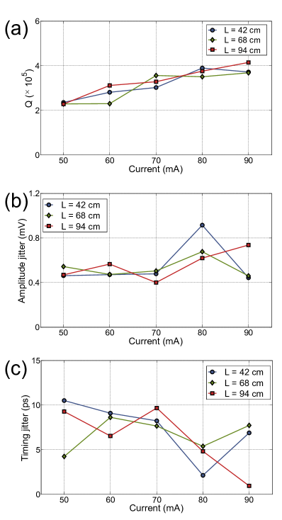
To evaluate the performance of OEOs, it is important to evaluate the quality factor , the amplitude jitter , and the timing jitter . is defined as the ratio of an oscillator’s carrier frequency to the full width at half maximum in its power spectrum and it can be used to estimate the bit-error rate of a digital communication system when the decision variable is assumed to be Gaussian (Agrawal, ; BerganoPTL, ; MateraQE, ). Here, is determined by fitting the RF spectrum to a Gaussian curve, as shown in the inset of Fig 3(b). In Fig. 5(a), as a function of at , , and cm with is determined to be , which is confirmed with a RF spectrum analyzer (Anritsu MS2830A). Amplitude jitter is calculated by demodulating with a sinusoid at the center frequency of and removing the resulting high-frequency term. Typical values of amplitude jitter seen in Fig. 5(b) are between 0.4 and 0.9 mV and, as a result, reduce . Timing jitter is also determined by demodulation and ranges from to ps. Side peaks separated, approximately, by multiples of can be observed in the RF spectrum of Fig. 2(c). We determined that the peak-to-pedestal ratio, based on the largest side peak, is typically larger than 25 dB.
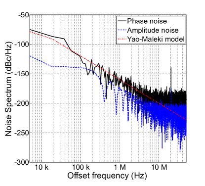
In Fig. 6, we plot the noise density spectrum for both amplitude and phase for mA, cm, and . We determined the phase noise to be -86.3 dBc/Hz at 20 kHz offset frequency. Due to resolution limitations, we are unable to obtain a direct measurement of the phase-noise spectral density at 10 kHz offset; however, we have fit our phase-noise spectrum to a Yao-Maleki model (Yao:96, ) and extrapolated the phase noise to be dBc/Hz at 10 kHz offset frequency. In addition, we confirmed that the value is smaller than -80 dBc/Hz for all values of current and delay tested in this paper.
Our OEO compared to tunable state of the art X-band OEOs can be seen in Table I. The OEOs used for comparison are an OEO based on a laser whose output is modulated by an external modulator before being optically injected into a Fabry-Perot LD (YaoFabry, ), an OEO using two cascaded phase modulators followed by a linearly chirped fiber Bragg grating (YaoBragg, ), and an OEO which uses a phase modulator followed by a tunable optical filter (ChenOEFilter, ). The tunability of our OEO ( to GHz) is slightly lower than two of the reported OEOs (the upper limit results from our oscilloscope bandwidth). Choosing a different LD, however, may result in a larger range of accessible . The phase noise of our OEO is somewhat larger than the competing approaches. However, it must be pointed out that our oscillator has a high factor and the advantage of a simpler design by not requiring optical to electronic conversion as in the other OEOs. Nor has our OEO been actively stabilized, and our noise measurements have been obtained following amplification which is likely to contribute to those measurements.
IV Conclusion
We have demonstrated the use of an ECL as a novel OEO tunable across the entire X-band, from 6.79 to 11.48 GHz. Both the optical and electrical signal can be employed for microwave applications; however, by using directly (upon which we concentrate here), we can entirely eliminate the need for O/E conversion, which is of interest for some applications. Specifically, is obtained by monitoring the voltage across the LD injection terminals under constant-current operation. The quality factor is greater than . In addition, we have characterized both amplitude and timing jitters with from 0.40 mV to 0.92 mV and ps. An estimated value of the phase noise spectral density at 10 kHz offset is found to be dBc/Hz. The phase-noise performance of our OEO setup may be improved by choosing the feedback time to be a multiple of the relaxation-oscillation time; in this way, one may average out phase fluctuations (KathyAPL, ; LinaPRA, ). Alternatively, a Pyragas-like feedback can be applied to control unwanted chaos and stabilize unstable orbits (PyragasPRA, ). This type of feedback is achieved by applying a continuous feedback term which is proportional to the difference of signal at and to the system. Such feedback scheme can be implemented by modulating the injection current with optoelectronic feedback as shown in (Turovets, ) or with impulsive delayed feedback (Naumenko, ). The combination of tunability and low phase-noise figures of merit indicates that the OEOs based on ECLs may be competitive with the state of the art. Future efforts will be geared towards stabilizing the device and determining the intrinsic performance before amplification.
Acknowledgment
We gratefully acknowledge the financial support of the Région Grand Est.
References
- (1) R.C. Williamson and R.D. Esman, “RF photonics,” J. Lightwave Technol., vol. 26, pp. 1145-1153, 2008.
- (2) L. Maleki, “The optoelectronic oscillator,” Nat. Photon., vol. 5, pp. 728-730, 2011.
- (3) J. Yao, “Microwave Photonics: Photonic Generation of Microwave and Millimeter-wave Signals,” Internat. J. Microwave Opt. Technol., vol. 5, pp. 16-21, 2010.
- (4) J. Yao,“Photonic generation of microwave arbitrary waveforms,” Opt. Commun., vol. 284, pp. 3723-3736, 2011.
- (5) J. -P. Zhuang and S. -C. Chan, “Phase noise characteristics of microwave signals generated by semiconductor laser dynamics,” Opt. Expr., vol. 23, pp. 2777-2797, 2015.
- (6) X. S. Yao and L. Maleki, “Converting Light into Spectrally Pure Microwave Oscillation,” Opt. Lett., vol. 21, pp. 483-486, 1996.
- (7) K. Volyanskiy, P. Salzenstein, H. Tavernier, M. Pogurmirskiy, Y. K. Chembo, and L. Larger, “Compact optoelectronic microwave oscillators using ultra-high whispering gallery mode disk-resonators and phase modulation,” Opt. Expr., vol. 18, pp. 22358-22363, 2010.
- (8) P. Zhou and S. Pan and D. Zhu and R. Guo and F. Zhang and Y. Zhao, “A Compact Optoelectronic Oscillator Based on an Electroabsorption Modulated Laser,” IEEE Photon. Technol. Lett., vol. 26, pp. 86-88, 2014.
- (9) R. Lang and K. Kobayashi, “External optical feedback effects on semiconductor injection laser properties,” IEEE J. Quant. Electron., vol. 16, pp. 347-355, 1980.
- (10) R. F. Kazarinov and R. Suris, “Heterodyne reception of light by an injection laser,” Sov. Phys.-JETP, vol. 39, pp. 522-527, 1974.
- (11) A. A. Sahai, B. Kim, D. Choi, A. Locquet, and D. S. Citrin, “Mapping the nonlinear dynamics of a laser diode via its terminal voltage,” Opt. Lett., vol. 39, pp. 5630-5633, 2014.
- (12) W. Ray, W. Lam, P. N. Guzdar, and R. Roy, ”Observation of chaotic itinerancy in the light and carrier dynamics of a semiconductor laser with optical feedback,” Phys. Rev. E, vol. 73, pp. 026219, 2006.
- (13) B. Kim, A. Locquet, D. Choi, and D. S. Citrin, ”Experimental route to chaos of an external-cavity semiconductor laser,” Phys. Rev. A, vol. 91, pp. 061802(R), 2015.
- (14) B. Kim, N. Li, A. Locquet, and D. S. Citrin, ”Experimental bifurcation-cascade diagram of an external-cavity semiconductor laser,” Opt. Exp., vol. 22, pp. 2348, 2014.
- (15) Q. Zou, K. Merghem, S. Azouigui, A. Martinez, A. Accard, N. Chimot, F. Lelarge, and A. Ramdane, ”Feedback-resistant p-type doped InAs/InP quantum-dash distributed feedback lasers for isolator-free 10 Gb/s transmission at 1.55 ,” Appl. Phys. Lett., vol. 97, pp. 231115, 2010.
- (16) A. Yariv and P. Yeh, Photonics: Optical Electronics in Modern Communications (The Oxford Series in Electrical and Computer Engineering). New York, NY, USA: Oxford University Press, Inc., 2006
- (17) J. S. Cohen and R. R. Drenten and B. H. Verbeeck, ”The effect of optical feedback on the relaxation oscillation in semiconductor lasers,” IEEE J. Quant. Electron., vol. 24, pp. 1989, 1988.
- (18) G. Acket and D. Lenstra and A. Den Boef and B. Verbeek, ”The influence of feedback intensity on longitudinal mode properties and optical noise in index-guided semiconductor lasers,” IEEE J. Quant. Electron., vol. 20, pp. 1163, 1984.
- (19) C. Y. Chang, D. Choi, A. Locquet, M. J. Wishon, K. Merghem, A. Martinez, F. Lelarget, A. Ramdane, D. S. Citrin, ”A multi-GHz chaotic optoelectronic oscillator based on a terminal voltage measurement,” Appl. Phys. Lett., vol. 108, pp. 191109, 2016.
- (20) G. P. Agrawal, Fiber-Optic Communication Systems., New York: Wiley, 1992.
- (21) N. S. Bergano, F. W. Kerfoot, and C. R. Davidson, ”Margin measurements in optical amplifier systems,” IEEE Photon. Technol. Lett., vol. 5, pp. 304-306, 1993.
- (22) F. Matera, and M. Settembre, ”Role of Q-Factor and of Time Jitter in the Performance Evaluation of Optically Amplified Transmission Systems” IEEE J. Sel. Top. Quantum, vol. 6, pp. 308-316, 2000.
- (23) S. Pan, and Jianping Yao, ”Wideband and frequency-tunable microwave generation using an optoelectronic oscillator incorporating a Fabry–Perot laser diode with external optical injection,” Opt. Lett., vol. 35, pp. 1911-1913, 2010.
- (24) W. Li, and J. Yao, ”A wideband frequency tunable optoelectronic oscillator incorporating a tunable microwave photonic filter based on phase-modulation to intensity-modulation conversion using a phase-shifted fiber Bragg grating,” IEEE Trans. Microw. Theory Tech., vol. 60, pp. 1735-1742, 2012.
- (25) X. Xie, C. Zhang, T. Sun, P. Guo, X. Zhu, L. Zhu, W. Hu, and Z. Chen, ”Wideband tunable optoelectronic oscillator based on a phase modulator and a tunable optical filter,” Opt. Lett., vol. 38, pp. 655-657, 2013.
- (26) X. Steve Yao and Lute Maleki, ”Optoelectronic microwave oscillator,” J. Opt. Soc. Am. B, vol. 13, pp. 1725-1735, 1996.
- (27) K. Lüdge, E. Schöll, E. Viktorov, and T. Erneux, Thomas, ”Analytical approach to modulation properties of quantum dot lasers,” Appl. Phys. Lett., vol. 109, pp. 103112, 2011.
- (28) L. Jaurigue, A. Pimenov, D. Rachinskii, E. Schöll, K. Lüdge, Kathy and A. G. Vladimirov, ”Timing jitter of passively-mode-locked semiconductor lasers subject to optical feedback: A semi-analytic approach,” Phys. Rev. A, vol. 92, pp. 053807, 2015.
- (29) K. Pyragas, ”Continuous control of chaos by self-controlling feedback,” Phys. Rev. A, vol. 170, pp. 421-428, 1992.
- (30) S. I. Turovets and J. Dellunde and K. A. Shore, ”Selective excitation of periodic dynamics in external cavity laser diodes,” IEEE Electron. Lett., vol. 32, pp. 42-43, 1996.
- (31) A. V. Naumenko, N. A. Loiko, S. I. Turovets, P. S. Spencer, and K. A. Shore, ”Controlling dynamics in external-cavity laser diodes with electronic impulsive delayed feedback,” J. Opt. Soc. Am. B, vol. 15, pp. 551-561, 1998.